AMAZON multi-meters discounts AMAZON oscilloscope discounts
Overview
Pressure is measured as a force per unit area. Pressure measurements are important not only for the monitoring and control of pressure itself but also for measuring other parameters, such as level and flow (through differential pressure). Pressure measurement is one of the most common measurements made in process control. It is also one of the simplest in terms of which measuring device to select. One of the key items to consider is the primary element (i.e., strain gage, Bourdon tube, spiral, etc.). Primary-element materials should be selected to provide sufficient immunity from the process fluids and at the same time the required measured accuracy under the process conditions they will encounter.
AMAZON multi-meters discounts AMAZON oscilloscope discounts
This Section provides some of the basic knowledge plant personnel will require to select the correct pressure-measuring device. However, it is essential that the instrument selector take into consideration the users' experiences.
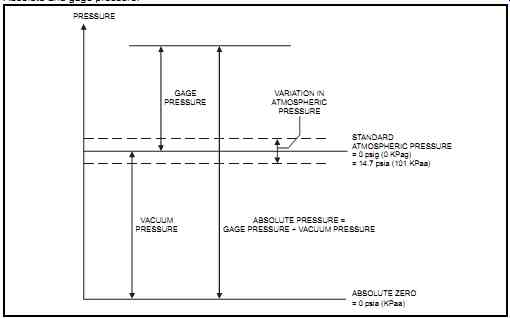
FIG. 1 Absolute and gage pressure.
Pressure-measuring instruments are really pressure transducers that convert the pressure energy into a measurable mechanical or electrical energy. Pressure measurement is always made with respect to a reference point. There are basically three types of pressure-sensing configurations (see FIG. 1).
1. Gage pressure, where the reference is atmospheric pressure
2. Absolute pressure, where the reference is complete vacuum
3. Differential pressure, which represents the difference between two pressure levels (note that gage pressure is a differential pressure between a value and atmospheric pressure)
In certain cases, pressure devices must conform to specific requirements. For example, on pressures greater than 15 psig (103 kPag) or in applications that contain lethal, toxic, or flammable substances, pressure devices may need to be registered, regardless of the design temperature. In oxygen service, the equipment should be degreased and ordered as such for this application, then labeled "FOR OXYGEN SERVICE." Individual countries may have specific requirements.
AMAZON multi-meters discounts AMAZON oscilloscope discounts
Units of Measurement
Most industrial pressure measurements function within a range between the atmospheric pres sure and the operating pressure. This pressure measurement is known as "gage pressure", it is a measurement that plant personnel commonly use. Units such as psig or kPag are used in these cases. When referring to units of pressure, it is important to ensure that the measuring units are correct (i.e., gage or absolute). In uses where the pressure is measured in absolute terms, as is the case in making engineering calculations (i.e., in reference to full vacuum), the units used are psia or kPa absolute (sometimes referred to as kPaa). Note that if the absolute pressure of the process remains constant and the atmospheric pressure increases, the gage pressure decreases.
Differential pressure is the difference between two process pressures. The common units of measurements are psi and kPa, although some plants use the psid and kPad terminology. Standard atmospheric pressure is equal to 14.7 psia (101.3 kPa absolute).
Gages (or Gauges)
Normally, pressure gages intended for field mounting are 4½ in. (about 120 mm) in diameter and contain a blowout disk and a standard bottom connection of ½ in. (or ¾ in.) male NPT (National Pipe Taper thread), unless different requirements are dictated by pipeline or vessel specifications. Instrument air applications typically use ¼ in. connections. Generally, the maximum working pressure to which a gage is subjected should be around 75 percent of full-scale pressure range.
Transmitters
A typical pressure transmitter consists of two parts: the primary element and the secondary element. The primary element (which includes the pressure sensor or pressure element) converts the pressure into a mechanical or electrical value to be read by the secondary element. It is the part that is most subject to failure since it faces the process conditions.
The secondary element is the transmitter's electronics: basically, a transducer to convert the output from the primary element into a readable signal such as 4-20 mA. Typically, electronic based sensors such as strain gages have a better response and a higher accuracy than mechanical-based types such as Bourdons (which are still acceptable in many applications).
Filled Systems and Diaphragm Seals
Filled systems are used to protect the sensing element from corrosive, toxic, or highly viscous fluids or sediments. They are also used to overcome the effects of deposits or solidification in the impulse line or in the sensing element, which may block the line or sensor. Filled systems consist of a diaphragm seal that is attached to a transmitter (or other pressure-sensing device), through either a capillary or a direct-mount-style connection, and a fill fluid (such as silicone oil). The thin diaphragm and fill fluid isolate the pressure-sensing elements from the process fluid. When pressure is applied, the diaphragm flexes and transfers the measured pressure through the fill fluid to the pressure-sensing element.
Where diaphragm seals are used, users should consider the following:
1. The potential need for a flushing connection since a plugged diaphragm will not perform as intended.
2. The diaphragm diameter is dependent on the measuring span and the temperature effects.
3. The rating and material of flanges must comply with the pipeline or vessel specifications.
4. The seal fill fluid must be compatible with the process fluid. This will prevent the introduction of unwanted seal fluid into the process following a diaphragm leakage. This is critical in applications that involve pharmaceuticals, foodstuffs, and hazardous chemicals.
Installation
Where process conditions permit, the common practice is to isolate all pressure instruments from the process with a valve. Such an isolating valve (and its associated piping/tubing) must comply with the piping requirements for the process fluid in question. This permits maintenance activities to be performed without having to shut down the operation. In most cases, the impulse piping must be kept as short as possible unless the need to protect the instrument from high temperature dictates the use of sufficient impulse piping to avoid damaging the instrument. High process temperatures require that heat be dissipated, and if condensation will occur, a pigtail siphon may also be required. Typically, siphons made of the proper material are required for all vapors above 140°F (60°C).
Protection may also be required from detrimental conditions such as pulsating pressure. Such protection is provided by using a dampening fluid or pulsation dampeners. These methods basically retard the instrument's rate of response. If pulsation dampeners are required, the materials they are made of must conform with the fluid being measured.
Test and drain valves may also be necessary. Isolating valves must be accessible to personnel from the ground or from a platform, and the entire system must provide accessibility for maintenance. If the fluid measured is toxic or corrosive, the plant must provide a blowdown valve and blowdown line.
If solids will accumulate in the impulse line, the plant must install tees and plug fittings (or ball valves) instead of elbows to allow plugged lines to be rodded. To maintain a constant hydro static head on the instrument, the impulse line should be free of liquids, for gas service, and should be filled with liquid, for liquid or vapor service.
Plant personnel must assess, based on the fluid being measured, whether the connection should be on the top or side of the process line. Typically, on liquid lines the connection is on the side to avoid traveling air or gas bubbles. For gas lines it is on the side or top to avoid condensing droplets. The instruments in gas applications should be self-draining, that is, lines are sloped toward the process to avoid trapping condensables and liquids. Instruments in liquid and condensable applications should be self-venting, that is, lines are sloped toward the instrument to avoid trapping of gas. Therefore, where possible, transmitters are mounted above the process lines for gas applications and below the process line for liquid applications.
Differential-pressure transmitters should have a valve manifold and sometimes a blowdown valve or vent valve. This manifold must be made of a material that meets the piping specification for the fluid in question. For additional information on manifolds, refer to the section "Differential Pressure" in Section 5 on level measurement.
Comparison Table
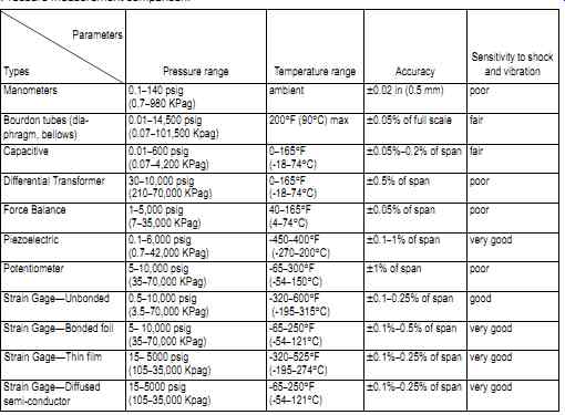
TABLE 1 summarizes the main types of pressure sensors with respect to a set of common parameters. The table can provide plant personnel with guidance on evaluation criteria for selecting pressure sensor devices. The information presented in TABLE 1 indicates typical values; vendors may have equipment that exceeds the limits shown.
TABLE 1 Pressure measurement comparison.
Manometer
Principle of Measurement
The manometer (see FIG. 2) is based on the principle of hydrostatic pressure and on the relationship between pressure and the corresponding displacement of a column of liquid. The same principles apply to the U-tube, where the process pressure supports a column of liquid of known density. The height of the liquid column is then read on a graduated scale. Pressure applied to the surface of one leg causes a liquid elevation in the other leg. Generally, the unknown pressure is applied to one leg and a reference pressure (typically atmospheric pres sure) to the other. The amount of elevation is read on a scale that is calibrated to read directly in pressure units.
Application Notes
Manometers are simple and provide direct operation. However, they are limited in application to low pressures and will not handle overpressures. They are typically used only in laboratories or maintenance shops.
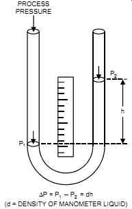
FIG. 2 U-tube manometer.
Bourdon Tube, Diaphragm, and Bellows
Principle of Measurement
In this method, process pressure is applied to a resilient, sealed container, usually a Bourdon tube, diaphragm, or bellows. The container, under pressure, will distort in a predefined way.
This mechanical movement is converted, through gears and pivots, into a pointer on a graduated dial. All three container types come in a variety of materials and thicknesses to cover different applications, process materials, and pressure ranges.
The Bourdon tube (see FIG. 3) consists of a bent oval tube. One end of the tube is linked to the process pressure, and the other end is sealed and linked to the mechanism operating the pointer. As the pressure increases, the tube tends to straighten itself out. This movement is indicated by the pointer. Bourdon tubes are generally available in spiral shapes for low-pres sure applications and in helical shapes for high-pressure applications.
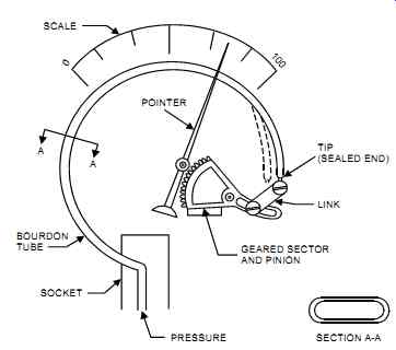 FIG. 3 Bourdon gage.
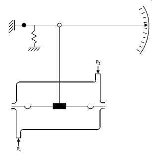
FIG. 4 Diaphragm gage (differential pressure).
The diaphragm (see FIG. 4) converts the increasing process pressure on one side of the disk (flat or corrugated) into a mechanical movement by monitoring the bulging of the disk. The diaphragm gage has a port diameter that is much larger than the Bourdon tube. It is therefore more capable of measuring low pressures and less prone to blockage. On the other hand, if the diaphragm ruptures there is a much higher leakage rate than with the Bourdon.
The bellows (see FIG. 5) is a one-piece axially expandable and collapsible element. A bellows consists of many folds. Its mechanical motion is similar to the diaphragm, but it has a wider span of movement.

FIG. 5 Bellows element gage.
Application Notes
Because of these instruments' principle of operation, their sensitivity tends to increase as their size increases. The response of the element may be affected by temperature changes, and mechanical components may wear over time. These instruments are most commonly used in pressure gages and pressure switches.
Capacitive Transducer
Principle of Measurement
In a capacitive transducer (see FIG. 6), the inlet pressure activates a diaphragm that is mounted between two fixed plates. This causes a capacitance change, which is measured in the electronic circuitry as a direct relation to pressure. Dual- or single-element units are available.
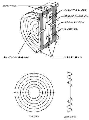
FIG. 6 Capacitive pressure transducer (differential pressure).
The dual elements tend to be extremely linear when compared to the single-element type.
Application Notes
Capacitive transducers have a proven track record and are commonly used. They provide excellent response, resolution, linearity, repeatability, and stability. In addition, since they are small and have low mass, inertia forces are low where vibration is present. However, they are relatively expensive and are sensitive to stray magnetic fields if they are not well designed.
Capacitive transducers are also affected by temperature changes and by variations in the dielectric constant of the process fluid.
Differential Transformer
Principle of Measurement
In differential transformers, the inlet pressure activates a diaphragm (sometimes a bellows may be used) that moves a magnetic core inside the transformer (see FIG. 7). This movement creates an imbalance in the secondary windings that is measured in the electronics and converted into pressure measurement.
Application Notes
These instruments provide excellent resolution, with low hysteresis. They are very rugged, and they have high overpressure capability and wide pressure ranges. However, differential transformers are massive, expensive, sensitive to stray magnetic fields, and have poor linearity.
They also are sensitive to acceleration and vibration.
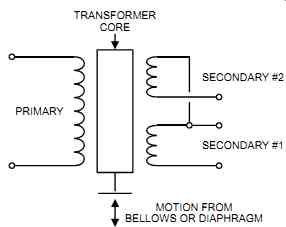
FIG. 7 Differential transformer.
Force Balance
Principle of Measurement
In force balances, the inlet pressure activates a bellows (see FIG. 8). This signal is amplified through the linkage and acts against a restoring force through a balance beam from an electromagnetic coil (or a servomotor). The movement created by the varying pressure is measured by a capacitive (or differential transformer) sensor. The term force balance comes from the forces exerted on the balance beam.
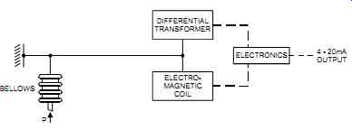
FIG. 8 Force balance electronic transmitter.
Application Notes
Force balance transmitters provide a high-level output, high resolution, and very good accuracy and stability, and they measure a wide range of pressures. However, they are relatively large in size and are sensitive to shock and vibration.
Piezoelectric
Principle of Measurement
In piezoelectric devices, the inlet pressure activates a diaphragm (sometimes a bellows may be used) that applies strain on a crystal (e.g., quartz) (see FIG. 9). The strained quartz produces an electrical charge that is measured by the electronics and converted into an output that indicates pressure.
There are two common types of piezoelectric crystals, those that occur in nature, such as quartz, and synthetic ones, such as Rochelle salts. Natural crystals are rugged and will with stand shock and high temperatures. Synthetic crystals produce a higher electrical output.
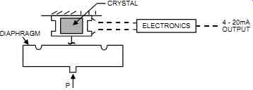 FIG.
9 Piezoelectric transmitter.
FIG.
9 Piezoelectric transmitter.
Application Notes
Piezoelectric sensors are rugged and small in size. They provide a very high frequency response and a linear output and do not require frequent calibration. However, they are sensitive to temperature changes (and thus must be temperature compensated) and recover poorly from overpressure.
Potentiometer, Wheatstone Bridge
Principle of Measurement
In potentiometers, the inlet pressure activates a diaphragm (or bellows) that moves a potentiometer wiper across a multiturn resistor (see FIG. 10). This movement causes a change in the potentiometer's resistance, sending a signal change to the Wheatstone bridge (see figure 11). The electrical signal generated is directly proportional to the displacement of the diaphragm.
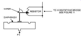
FIG. 10 Potentiometer transmitter.
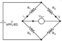
FIG. 11 Basic Wheatstone bridge.
The Wheatstone bridge was one of the earliest electrical devices to accurately measure resistance. The Wheatstone bridge's circuit has four resistors. If R1 and R3 are fixed resistors, then a change in R2 will have to be balanced against R4, with the value of R4 varied until:
Vout
= 0
(I2 x R2) / (I2 x R4) = (I1 x R1) / (I1 x R3)
Therefore:
R2 / R4 = R1 / R3
And the unknown resistance, R2 = R4 (R1 / R3)
The Wheatstone bridge is used to measure temperature, pressure, weight, and the like. In all these cases, R2 is used as an RTD or a strain gage, depending on the application.
Application Notes
Potentiometers are simple and inexpensive and provide a high-level output. However, the friction between the wiper and the resistor, along with bearing friction at the linkage, causes hysteresis. In addition, pressure fluctuations and vibrations accelerate the wear on the wiper/ resistor combination. Potentiometers have a limited life and below-average resolution.
Strain Gage: General Information
Principle of Measurement
Several types of strain gages are available, all of them based on the principle that any material changes its resistance when it is stretched. Strain gages are the most commonly used type of pressure-sensing element for pressure transmitters. Strain gages also are used in weight measurement and strain measurement in concrete and metal structures.
In strain gages, a displacement is caused by the increasing or decreasing pressure. This displacement causes a change in the length of the element, which is part of a Wheatstone bridge circuit. The change in resistance within the bridge is converted, through electronics, into a pressure value. In addition, the circuitry can easily adjust the zero output level, the span of measurement, and the ambient temperature effects (through automatic temperature compensation).
Application Notes
Since the change in resistance is very small, the electronics of the strain gage must be sensitive enough to detect such minute changes. Strain gage sensors have proven performance and pro vide reliable data. They are available from most vendors and offer better performance for the cost than thin-film or semiconductor sensors. However, strain gages are sensitive to tempera ture variations, and thus temperature compensation is necessary.
Strain Gage: Unbonded
Principle of Measurement
An unbonded strain gage (see FIG. 12) has a frame that consists of stationary and movable parts. A wire (about 0.4 mil in diameter) is located on both parts and is wrapped around non conductive posts. Wire tension increases and decreases with changes in pressure. When the movable part is displaced, this strains the wire(s) and increases or decreases the resistance accordingly. The electronics convert this resistance measurement (through the Wheatstone bridge) into a pressure output. Sometimes four wires are used, two in tension and two in compression.
Application Notes
Unbonded strain gages can accommodate overtravel stop limits. This provides mechanical overpressure protection. They have a low mass and long-term stability. However, they are sensitive to shock.
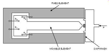
FIG. 12 Unbonded strain-gage pressure transmitter with four wires.
Strain Gage: Bonded
Principle of Measurement
In a bonded strain gage (see FIG. 13), a foil (or wire) is bonded to a diaphragm. Changes in pressure cause the diaphragm to flex, which in turn is sensed by the foil (or wire). Sometimes four strain gages are used as a set: two near the center of the diaphragm, where they encounter maximum tangential strain, and two near the circumference, where they encounter maximum radial strain. This is an improvement over the unbonded type since it eliminates the posts and frame.
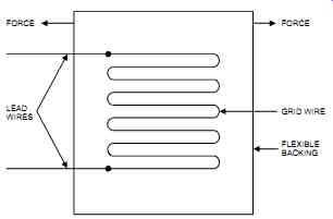
FIG. 13 Bonded foil strain-gage pressure transmitter.
Application Notes
Bonded strain gages offer a rugged assembly and good accuracy that is not degraded by shock and vibration. However, bonded strain gages are limited in their pressure and temperature ranges.
Strain Gage: Thin Film
Principle of Measurement
Thin-film strain gages (see FIG. 14) are very similar to bonded-foil strain gages except that integrated-circuit technology and processes are used to fabricate them. Laser trimming is used to obtain the exact resistance for each strain element, and the strain element is produced by vacuum deposition directly into the diaphragm.
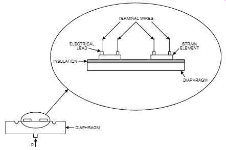
FIG. 14 Thin-film strain gage pressure transmitter.
Application Notes
Thin-film strain gages provide the best response and sensitivity of any strain gages, but they tend to be the most expensive. They are stable, with no or very little creep, and they provide good immunity to vibrations. They also have good long-term stability (including resistance to sensitivity and thermal shifts). However, distortion of the sensor case may cause major measurement errors. In addition, thin-film strain gages are of limited advantage in high tempera ture applications due to the nature of semiconductors, and they are not as rugged as unbonded strain gages. Also, they are more sensitive to transient voltages and radio frequency interference (RFI).
Strain Gage: Diffused Semiconductor
Principle of Measurement
The diffused semiconductor type of strain gage (see FIG. 15) uses integrated-circuit manufacturing techniques. The strain gage is diffused in a silicon element, which is the mechanical structure.
FIG. 15 Diffused semiconductor strain gage pressure transmitter.
Application Notes
Diffused semiconductor strain gages provide good long-term stability and good immunity to vibrations. However, they are limited in high-temperature applications due to the nature of semiconductors.