AMAZON multi-meters discounts AMAZON oscilloscope discounts
Overview
Temperature is a widely used measurement. Galileo is credited with inventing the first thermometer in 1595. Over the years thermometer technology has evolved, and measuring principles are continuously improved upon. Today, highly accurate and reliable devices are available. This Section provides some of the basic knowledge users need to select the proper temperature-measuring device. However, it is essential that the instrument selector take into consideration the users' experiences.
AMAZON multi-meters discounts AMAZON oscilloscope discounts
For process applications, a typical temperature measurement assembly consists of a thermo well, a temperature element, sometimes extension/connecting wires, and a temperature transmitter (local or remote). Temperature elements frequently include a spring-loaded mechanism to ensure that the element tip makes positive contact with the internal bottom of the well.
Temperature elements should be installed where good mixing is ensured, such as in pipe bends and in the liquid phase (if a vapor/liquid interface exists). The optimum immersion length for temperature elements varies with the application. If they are installed perpendicular to the line, then the tip of the element should be between one-half and one-third the pipe diameter. If they are installed in an elbow (the recommended option), with the tip pointing towards the flow, about one-quarter pipe diameter is sufficient since the flow is impinging on the tip of the temperature element.
Units of Measurement
The most commonly used units of temperature measurement are the Fahrenheit scale and the Celsius scale. The Fahrenheit scale was invented by Daniel G. Fahrenheit and published in 1724. It is still extensively used in the United States, although some industries are gradually converting to Celsius. The Celsius scale was developed by Anders Celsius, a Swedish scientist, in 1742.
Degrees Fahrenheit (°F), degrees Celsius (°C), and Kelvin (K, used mainly for scientific work) are recognized internationally as scales for measuring temperature. The Fahrenheit and Celsius scales have been developed from two fixed points: ice and steam, at atmospheric pressure.
Conversion from one scale into the other follows these equations.
Classification
Physical properties that change with temperature are used to measure temperature. For example, the property of material expansion when heated is used in liquid-in-glass, bi-metallics, and filled-system measurement. The electromotive force (emf) principle is used in thermocouples, and electrical resistance changes are used in resistance temperature detectors (RTDs). Other means of temperature measurement include temperature-sensitive paint and crayons, and optical devices.
In the traditional medical thermometer, liquid-in-glass measurement takes the form of mercury enclosed in glass. Obviously, the delicate nature of the glass and the toxicity of mercury limit the usefulness of this type of thermometer in industrial applications. An improvement on the liquid-in-glass thermometer is the filled system.
Temperature-sensitive paint and crayons can be applied to a surface to determine its tempera ture. Some of them are reversible, such as desktop thermometers, while others are irreversible.
They are available in a wide range of temperatures. Crayons have a calibrated melting point, and the crayon mark melts when the rated temperature is reached. Paints, which are suspended in a medium, function similarly. Both crayons and paints have ranges varying from 120 to 2000°F (50 to 1090°C).
Thermowells
Thermowells (T/Ws) are used to protect the element (which is typically fragile) and to make it easier to replace the element without interrupting the process (see FIG. 1). If a plant does not need a well, for safety reasons, a label should be attached to the element to indicate that no well is present. The downside of T/Ws is that they create a time delay. If, for example, a temperature measurement without a well has a 1 to 10 seconds time delay, with a well the measurement may degrade to a 20 to 50 seconds delay.
Thermowells are used in most cases where temperature elements are installed, with some exceptions.
• The internals of some equipment (e.g., compressors, turbines, etc.)
• Bearings where space is very limited
• In measuring surface temperature
• In fast-response applications (i.e., if thermowells create too much of a delay)
• In measuring air-space temperature
Thermowells must comply with the pipeline's or vessel's specifications. The thermowell's construction and material must be carefully matched with the process requirements (including abnormal and emergency conditions). Many plants have standardized the connection size and material of wells, for example:
• The well connection to the process has been standardized to 1½ in. flanged or 1 in. NPT (National Pipe Taper thread). This connection should always comply with the piping specification. Note that the exposed part of the well will conduct heat to the pipe surface, and thus insulation may be required.
• The well material has been standardized to 316 SS material, with special applications requiring special materials. Thermowell material will vary with the application and the required speed of response. The maximum recommended temperature for metal T/Ws varies from 800°F (425°C) for iron to 2300°F (1260°C) for Inconel. For ceramic tubes, the maximum temperature varies from 1900°F (1050°C) for fused silica to 3000°F (1650°C) for silicon carbide.
=======
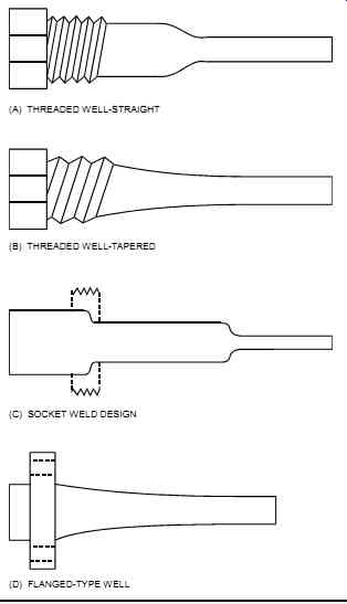
FIG. 1 Thermowells.
(A) THREADED WELL-STRAIGHT; (B) THREADED WELL-TAPERED; (C) SOCKET WELD DESIGN; (D) FLANGED-TYPE WELL
=======
Comparison Table
TABLE 1 summarizes the main types of temperature measurement with respect to a set of common parameters.
TABLE 1 Temperature measurement comparison. [coming soon]
===
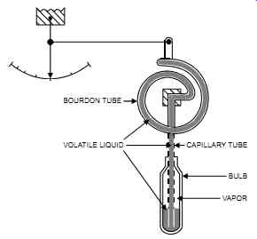
FIG. 2 Filled system.
VOLATILE LIQUID, VAPOR, BULB, CAPILLARY TUBE, BOURDON TUBE
===
This comparison table can be used as a selection guide. Note that the information presented in TABLE 1 indicates typical values; vendors may have equipment that exceeds the limits shown.
Filled System
Principle of Measurement
A filled system (see FIG. 2) is a metallic assembly that consists of a bulb, small-diameter tubing (known as capillary), and a Bourdon spring. An indicator linked to the Bourdon tube indicates temperature. Sometimes bellows and diaphragms are used instead of a Bourdon.
The system is filled with a liquid or gas that expands and contracts as the temperature sensed at the bulb increases and decreases. This expansion/contraction is translated into a mechanical motion. Liquid causes volume changes, and gas causes pressure changes.
Application Notes
The filled-system type of measurement is generally used for local indication or for temperature sensing in self-actuated temperature control valves. Its use has decreased over the years, but there are still some applications for it. This device is an improvement over the liquid-in-glass thermometer. It needs no power to function and is simple, rugged, self-contained, and accurate over narrow temperature spans.
However, the unit's bulb may be too large to fit existing applications, and if the filled system fails, the whole system must be replaced, which is expensive. In addition, the capillary tubing is generally limited to a distance of 250 ft (80 m), and the filled system as a whole is slow to respond and relatively expensive. Moreover, it is susceptible to ambient temperature changes around the capillary, and ambient temperature compensation is often necessary.
Filled-system measuring devices must be free of leaks in order to maintain their accuracy.
Therefore, plants must occasionally check and test them, and continuously support and protect the capillary tubing against damage. In addition, the capillary's material of construction should be compatible with the surrounding environment. Finally, the bulb must be sufficiently immersed to ensure that the actual temperature is being measured.
Bimetallic
Principle of Measurement
In a bimetallic device (see FIG. 3), a spiral made of two metals with different coefficients of expansion expands as the temperature increases. The movement generated by the expansion drives an indicator on a scale. Industrial bimetallics use a helical coil to fit inside a stem. Most temperature switches operate on this principle, except that the pointer is replaced with a microswitch. Precision-made bearings and guides provide minimum acceptable friction for the moving components.
===
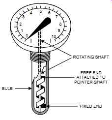
FIG. 3 Bimetallic.
===
Application Notes
The bimetallic method of measurement is generally used in local temperature gages and switches. To facilitate the reading of process temperatures, plants usually select "all-angle" gages with a 5 in. (120 mm) diameter dial. A capillary type is sometimes used for operating visibility. If vibration exists, the plant may have to fill the thermometer with a dampening fluid that is compatible with the process fluid, in case of leakage.
The bimetallic has a simple construction and few moving parts and requires little maintenance.
Its cost is the lowest of all temperature-measuring devices. However, its accuracy is low, and it provides no remote indication. Calibrating bimetallics requires immersing them in a bath of known temperature.
Thermocouple
Principle of Measurement
In 1821, T. J. Seebeck discovered that when two dissimilar metals are joined together, an electromotive force (emf) is generated between the hot and cold (reference) junctions (e.g., 4 mV for 100°C between the two junctions). An increase in temperature produces an increase in volt age output. Originally, the "cold" junction was actually immersed in an ice bath to maintain a constant reference temperature. Modern electronics have replaced this ice bath.
Theoretically, any two dissimilar metals will form a thermocouple (T/C) (see FIG. 4). How ever, only a few are used because of their superior response to temperature changes (i.e., sensitivity) and performance in general. There are many types of thermocouples, each with its advantages and disadvantages-refer to TABLE 1.
Thermocouple wires are manufactured to close tolerances and tend to be expensive. Their use is thus limited to the probe itself. Thermocouple extension wires, which are compatible with the T/C wires, are used as the link between the T/C and the measuring device or transducer.
The evolution of modern electronics has created transducers that are small enough to fit inside the T/C box (or head). The major advantage of this arrangement is that it avoids long-distance transmission of a very low T/C voltage signal, which is prone to electrical noise (as opposed to the 4-20 mA signal).
======
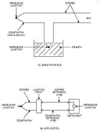
FIG. 4 Thermocouples.
MEASURING JUNCTION COPPER EMV ICE BATH CONSTANTAN (40% Ni,60% Cu) REFERENCE JUNCTION (A) BASIC PRINCIPLE COPPER JUNCTION POINT COPPER EXTENSION WIRE INSTRUMENT CONSTANTAN EXTENSION WIRE CONSTANTAN MEASURING JUNCTION REFERENCE JUNCTION (B) APPLICATION
======
EMF Calculations
For each type of thermocouple there is a corresponding reference table that converts mV reading (i.e., thermocouple output) into a temperature. These tables are available from many sources and vendors, including National Bureau of Standards Monograph 125, ISA Recommended Practices, or ISA Standards (ISA-MC96.1-1982). As an example, a portion of a K type reference table is shown in TABLE 2. From that table, it can be seen that if a K-type thermocouple has an output of 4.012 mV and the temperature of the reference junction is at 0°C, then the measured temperature is of 98°C.
Note that sometimes the mV values must be interpolated from the table to obtain the corresponding temperature. Linear interpolation is acceptable.
Application Notes
The three basic types of T/C construction are the following:
1. Ceramic beaded.
2. Insulated (plastic, glass, or ceramic fiber). These types are generally extruded (see FIG. 5).
3. Metal-sheathed mineral-insulated (MSMI). The sheath is generally stainless steel or Inconel, and mineral insulation is generally magnesium oxide or aluminum oxide.
Sheathed material gives the T/ C excellent protection from outside chemical and mechanical effects. However, sheathed T/Cs, since they are a one-piece construction, are more difficult to strip and terminate than other types. The junction should be welded and insulated.
Different types of sheathed thermocouples are shown in FIG. 6.
TABLE 2 Partial type K thermocouple temperature - emf table.
=====
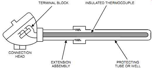
FIG. 5 Typical thermocouple assembly.
TERMINAL BLOCK INSULATED THERMOCOUPLE CONNECTION HEAD EXTENSION ASSEMBLY PROTECTING TUBE OR WELL
=====
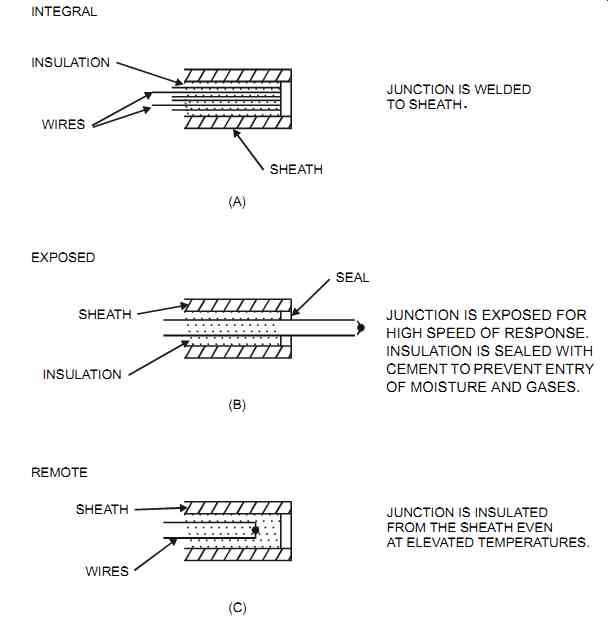
FIG. 6 Sheathed thermocouples.
=====
T/Cs can be constructed so as to be exposed or protected. Exposed T/Cs provide the fastest response, but the wires are totally unprotected. Protected T/Cs can be grounded or ungrounded.
When grounded they give a faster response since good temperature transfer is obtained. How ever, grounded-protected T/Cs are susceptible to electrical noise due to stray electrical signal pickup. When T/Cs are ungrounded, they are slower to respond but are electrically isolated. In addition, a T/C may be spring-loaded in the thermowell so that its tip and the well's surface remain in contact to ensure good heat transfer.
T/C wire is available in different gauges. As the T/C wire gets thinner, the recommended upper temperature limit is reduced. For example, the upper limit for a type J T/C is 1400°F (760°C). With a No. 8 gage T/C wire, it is 1095°F (590°C), with a No. 14 gage T/C wire it is 895°F (480°C), and 700°F (370°C) with a No. 24 gage T/C wire.
• the error decreases and the response is faster to temperature changes.
• the element becomes more fragile (i.e., more frequent maintenance is required).
• at high temperatures, the accuracy is more sensitive to material quality (wire impurities, etc.).
T/Cs are identified through color coding. All color coding, accuracy, and symbol designation for T/Cs and extension wire should conform with the local authority that has jurisdiction at the site. For example, a typical authority is the ISA-MC96.1-1982 where the negative wire is always red in color.
Thermocouples are self-powered and of simple and rugged (shock-resistant) construction.
They are also inexpensive (half the price of an RTD), come in a wide choice of physical forms, and provide a wide temperature range. In addition, they can be calibrated to generate a specific curve (for an extra cost) and are easy to interchange. They provide a fast response and measurement at one specific point. The typical response time of a bare T/C is from 0.2 to 12 seconds.
Whereas RTDs average the temperature over their element, T/Cs measure the temperature at their tip only and are thus faster. However, T/Cs generate a nonlinear output and a low voltage.
The accuracy of T/Cs varies with temperature. Therefore, plants must assess the T/C's accuracy at the operating temperature to determine whether it is acceptable.
T/Cs require a reference junction, have low sensitivity, are limited in accuracy, and need type matching extension wires. In addition, they are subject to deterioration from adverse conditions, usage, and time; are susceptible to stray electrical signals; and require amplifying electronics. However, the unit's electronics can identify T/C failure as being either an upscale or downscale indication.
Resistance Temperature Detector (RTD)
Principle of Measurement
Pure metals will produce an increase in resistance with an increase in temperature. In resistance temperature detectors (RTD), the electronics sense the change of resistance of a resistor (on a Wheatstone bridge) as temperature changes and generate a proportional output. For more information about the Wheatstone bridge, refer to FIG. 11. The most common RTD element is 100 ohm at 0°C platinum; nickel is generally the second choice. The RTD is an accurate sensor that theoretically could measure a temperature change of 0.00002°F (0.00001°C).
Resistance temperature detectors are usually protected from the environment by a sheath made of stainless steel or any other temperature- and corrosion-resistant material (see FIG. 7).
The element fits snugly inside the sheath to produce a high rate of heat transfer. A fine powder is used to eliminate air pockets. Ceramic insulators are typically used to isolate the internal lead wires. At the end of the tube a hermetic seal protects the element. The assembly may be terminated with the lead wires or may be supplied with an appropriate terminal block similar to a T/C assembly.
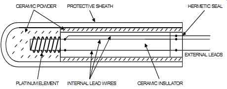
FIG. 7 Three-wire RTD. Components: CERAMIC POWDER PLATINUMELEMENT INTERNAL LEAD
WIRES CERAMICINSULATOR PROTECTIVE SHEATH HERMETIC SEAL EXTERNAL LEADS
Application Notes
As a rough rule of thumb, RTDs are used where the temperature is less than 250°F (120°C), whereas T/Cs are used where the temperature is greater than 930°F (500°C). Since the accuracy of RTDs varies with temperature, the user must assess the process's operating temperature and deemed whether an RTD is acceptable.
Resistance temperature detectors are available as two-wire, three-wire, and four-wire elements.
With a two-wire element (see FIG. 8A), the effect of the lead wire resistance (and the effects of the change in resistance that occurs as the ambient temperature changes) introduces significant errors.
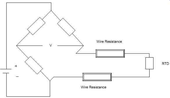
FIG. 8A 2-Wire RTD.
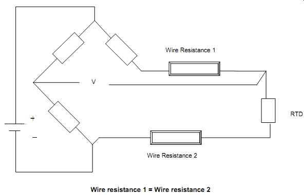
FIG. 8B 3-Wire RTD. Wire resistance 1 = Wire resistance 2
FIG. 8C 4-Wire RTD.
With a three-wire element (see FIG. 8B), the impedance in the wires will cancel because the wires are in opposite legs of the bridge. In other words, the three-wire method compensates for the effect of lead resistance. This is the most practical and commonly used RTD method. A four-wire element (see FIG. 8C) requires an extra wire but provides additional accuracy. It is generally used only rarely where very high degrees of accuracy are required. The four-wire element is immune to lead resistance. Its current is sourced on one set of leads and the voltage is sensed on another set of leads. The lead resistance is not part of the measurement and the output voltage is directly proportional to the RTD resistance.
Of all temperature-measuring devices, RTDs are, at moderate temperatures, the most stable and the most accurate. Their output is stronger than that of a T/C, they are less susceptible to electrical noise, and they operate on a higher level of electrical signals. Moreover, they are more sensitive and more linear than a T/C (output versus temperature), use copper extension wire (not special extension wire), require no reference junction, and are easy to interchange.
However, RTDs are relatively expensive compared to thermocouples, have a slow response, and require a current source. They are susceptible to small resistance changes, and self-heating appears as a measurement error (the main source of RTD error). In addition, RTDs have a limited temperature range, are susceptible to strain and vibration, generate some nonlinearity, and require three (or four) extension wires. Their resistance curves vary from manufacturer to manufacturer, and their accuracy and service life are limited at high temperatures.
Thermistor
A thermistor is basically a semiconductor that is performing the function of an RTD, but with a higher resistance. The resistance change (due to a temperature change) is about ten times that of a metallic RTD. However, the self-heating error is high, and the resistance values are nonlinear, which limits the thermistor's measuring range.
Noncontact Pyrometry
Principle of Measurement
Pyrometry is based on the principle that all objects emit radiant energy in the form of electro magnetic waves. "Red hot" means that the radiant energy is in the visible light portion of the spectrum. Pyrometers measure the temperature of an object by measuring the intensity of the emitted radiation (visible or non-visible). Emitted radiation is a measure of an object's ability to send out radiant energy. A black body is considered as the perfect emitter and is commonly used as a standard when calibrating pyrometers. The two most common pyrometric techniques are radiation and optical.
Radiation
In radiation pyrometry, the radiation from a hot surface is measured when it is focused on a T/C. The measured temperature is directly proportional to the heat radiated and therefore its temperature (if the emissivity is known). The instrument calibration is based on a blackbody radiation; if targeting non-blackbodies, correction must be applied (see FIG. 9).
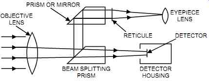
FIG. 9 Typical radiation pyrometer.
Optical
In optical pyrometry, the radiant energy from the filament inside the instrument is compared to the incoming radiant energy by manually (or automatically) adjusting the rheostat. The radiant energy of the filament blends into the measured radiant energy. This type of device is some times known as the "disappearing filament." The value of this radiant energy (i.e., the current measured) is converted into degrees if the emissivity is known (see FIG. 10).
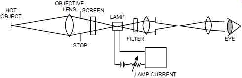
FIG. 10 Typical optical pyrometer.
Application Notes
Pyrometry is used for noncontact measurement where the point to be measured is out of reach (such as a moving target or an inaccessible target). It is also used to measure the average temperature of a very large target, or if the temperature is too high (such as with molten metal).
Pyrometers may be portable, and they have a high response speed of a few milliseconds. For industrial-type meters, a one- to two-second response time is common. Pyrometers are relatively expensive. In addition, errors can be introduced in pyrometers through condensation on the window or lens, smoke or fumes in the atmosphere, gases such as products of combustion, or dirt on the optical system. For fixed units, a special housing may be required to protect units that are subject to extremely high surrounding temperatures (e.g., cast aluminum jackets to accommodate coolants). Special housings may also be needed to meet production needs (e.g., water cleaning, sprays, etc.) or to protect units from cold winters (where heat tracing may be required).
Pyrometers may require the use of focusing devices, such as sighting telescopes, alignment tubes, and aiming flanges. They may also require the use of safety shutters to safeguard the lenses and motorized bases to redirect the instrument's position.