AMAZON multi-meters discounts AMAZON oscilloscope discounts
As the old cliché says, a picture is worth a thousand words. This expression is as true in electronics as it’s anywhere, maybe even more so. It’s impossible to imagine working in the electronics field without using diagrams and drawings. There are several basic types of diagrams commonly used in the electronics field. For the most part, these various diagram types can be grouped into three bread categories:
-Pictorial diagrams
-Block diagrams
-Schematic diagrams
Each of these will be discussed in this section.
Pictorial diagrams
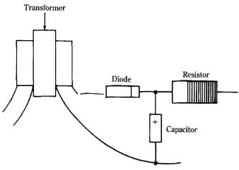
The most basic diagram you will encounter in electronics work is the pictorial diagram. Though widely used, the pictorial diagram is probably the least useful, al though it can be helpful in certain cases. A pictorial diagram is simply a drawing of the way a circuit or piece of equipment should look. This drawing can be useful for hobbyists building a project, or in repairing a piece of equipment that has been modified from its original design. A typical pictorial diagram is shown in FIG. 1. It tells you nothing more than a photograph of the circuit would tell you.
A slightly more sophisticated form of the pictorial diagram is the exploded diagram. An example is shown in FIG. 2. In an exploded diagram, the various parts are shown in their relative positions to one another, but are moved apart so notice them easier. Lines show how the parts are interconnected. Generally, exploded diagrams are not used for circuits. They are used to show how circuit boards and bulky components (such as heavy power transformers) are mounted within a case and how the case is assembled.
- --1 Pictorial diagram.
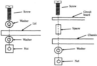
- --2 Exploded diagram.
Component placement diagrams are often used with projects that are built on printed circuit boards. If you are not familiar with printed circuits, don’t worry about it; they are covered in section 15. A component placement diagram shows the correct position for each component mounted on the printed circuit board. This feature is important, because if a component is misplaced (with one or more leads in the wrong hole), the circuit won’t function properly. Off-board components, or connections to other boards, are also indicated. Usually just a labeled lead line coming off the board at the appropriate point is shown. To keep things simple and to avoid wasted effort, the actual off-board device(s) is generally not drawn, although it might be shown in some diagrams, if the technician drawing the diagram thinks this will offer more information to someone using the diagram later. A typical component placement diagram is shown in FIG. 3.
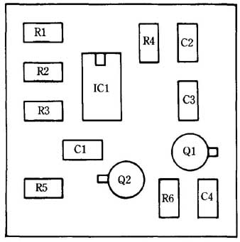
--- 3 Component placement diagram.
Block diagrams
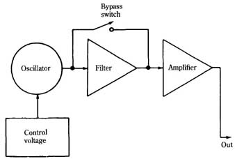
Pictorial diagrams show how a circuit is physically constructed, but tell you nothing about how the circuit works, or even what its intended purpose is. Block diagrams are more useful for understanding circuit operation. Some technicians refer to block diagrams as functional diagrams.
Except for very simple circuits, most electronic systems are made up of multiple sub-circuits. Each sub-circuit performs a specific function or set of related functions. The various sub-circuit functions work together to achieve more powerful and versatile results. In a block diagram, each sub-circuit is shown simply as a block. The actual components used to make up the sub-circuit are ignored. When you are reading a block diagram, you are only concerned with what the circuit does, not how it does it. Each sub-circuit is considered a black box. You know what the black box is supposed to do, but you use it as if you have no way of looking inside. If the input is A, then the output is B. The function or name of each sub-circuit is written in the appropriate block.
Occasionally a few components are shown separately in a block diagram. The separate diagram usually is drawn if the component is not part of any specific subcircuit and in essence functions as a sub-circuit by itself. Feedback components that connect several blocks, or stages, are usually drawn separately, as are interstage switches, plugs, and jacks. A typical block diagram is shown in FIG. 4.
In some block diagrams, special shapes are used to indicate certain functions. For example, circles are normally used to indicate oscillators or signal sources, and triangles are used to represent amplifiers. The diagram in FIG. 4 is redrawn using this system in FIG. 5. There is no functional difference in the two types of block diagrams. Some people find the varied shapes of the second version easier to read at a glance. Generally, which system you use will be strictly a matter of personal preference.
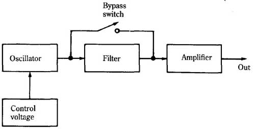
- --4 Block diagram. Bypass switch; Out
- --5 A different way of drawing the block diagram.
Schematic diagrams
The most important and most frequently used type of diagram in electronics work is the schematic diagram. A schematic diagram (sometimes known as a wiring diagram) shows all of the components in the circuit and how they are electrically interconnected. The position of any given component in a schematic diagram doesn’t necessarily correspond to its actual position in the physical circuit. The arrangement of the components in a schematic diagram is influenced more by the clarity of the diagram than by any specific construction details.
Straight (usually) lines are used to represent interconnecting wires and leads between components. As a rule, the schematic diagram should be drawn so that as few lines as possible cross each other where there is no electrical connection. Unfortunately, in most circuits of any complexity, a few line crossings are inevitable. Certain conventions are followed to prevent confusion. There are three commonly used standards.
In the first of these systems, a dot is used to indicate an electrical connection between two crossing leads. if there is no dot, there is no electrical connection. This system is shown in FIG. 6.
[Fig. coming soon] --6 First system used to indicate crossed wires. Electrical connection--- No connection
Some technicians prefer to use the second system, shown in FIG. 7. Here, a crossing of any two lines assumes that there is an electrical connection between them. if there is to be no electrical connection, and the lines just cross in the diagram, a small loop is made in one of the crossing lines. The loop indicates that the one wire jumps over the other without touching (without making electrical contact).
[Fig. coming soon]- --7 Second system used to indicate crossed wires. Electrical connection--- No connection
The third system is a combination of the first two. This third system leaves the least room for error. As shown in FIG. 8, a dot is used to indicate an electrical connection between a pair of crossing lines. When there is no electrical connection, the jumping loop is used. No two lines ever simply just cross each other, because this is potentially confusing. This convention is used in all the schematic diagrams in this book.
[Fig. coming soon] -8 Third (and least ambiguous) system used to indicate crossed wires.
Standardized schematic symbols are used to indicate various component types. These symbols are introduced in the appropriate section for each type of component. Some of the most important (and most commonly used) component symbols for the components you have learned about so far are shown again in FIG. 9. Those components are: resistor (A), capacitor (B), coil or inductor (C), transformer (D), SPST switch (E), and pushbutton switch (F).
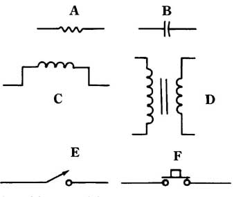
- --9 Schematic symbols. Resistor (A); capacitor (B); coil (C); transformer
(D); SPST switch (E); push button switch (F).
Many schematic diagrams also indicate certain electrical parameters that can be measured at specific test points within the circuit. The indicated parameters are most commonly voltages, currents, or waveforms. If the circuit is functioning properly, you should be able to measure the same values as those indicated in the schematic diagram. It’s usually important to use test equipment with the same specifications as the equipment used to determine the original values shown in the schematic, or you might not get the same results.