AMAZON multi-meters discounts AMAZON oscilloscope discounts
This section describes a wide range of applications for the technician’s right arm: the multimeter.
VOM = Volt-Ohm-Meter
VTVM = Vacuum-tube Volt Meter (more info)
Measuring contact resistance with a VOM
Once in a while you need to test a switch or relay contact to see if it’s making good contact. A bad contact is annoying, especially if it’s intermittent. However, there is one positive test: checking the resistance of the contact by reading the voltage across it in actual use. This test hook-up is simple, as illustrated in Fig. 1.
The contact resistance of a good switch should be 0—there should be absolutely no voltage drop across the contacts under full normal load. If the contact surfaces become dirty or burned, there will be resistance. Where there’s resistance, there’s heat, voltage drop, etc.
To check for contact resistance, set your voltmeter to the full line voltage of the circuit and connect it directly across the contacts. The voltage can be either ac or dc; just set the meter to read the full voltage that the switch is breaking. With a sensitive meter, you’ll see the full voltage across an open switch, even if the load circuits have fairly high resistance. Now, close the switch; the voltage should drop too. Turn the switch on and off several times to see if the voltage does drop to 0 every time.
If there is any contact resistance, you’ll see a small voltage reading when the contacts are closed. In most cases, this can be read with your initial meter setting. If you want to, turn the meter to a lower voltage scale for a more accurate check, but be careful. The contact could be intermittent, and any resulting surge of volt age could damage the voltmeter (unless it’s a VTVM).
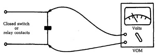
FIG.1 It’s very simple to measure contact resistance with a VOM. Closed
switch or relay contacts
With the meter set on the maximum voltage scale, tap the switch with the handle of a screwdriver to see if you get any difference in the reading. It’s a good idea to do this before going to a lower voltage scale with a VOM.
It takes only a very small voltage to show you that there is unwanted contact resistance. Even 0.5 V means that there is some resistance between the contacts. This resistance will tend to increase in time, and the switch might eventually burn out. (Resistance makes heat; heat makes more resistance—it’s a vicious circle.)
If the contacts are accessible as in some relays, you should clean them with very fine sandpaper or crocus cloth and a con tact-burnishing tool, or even a piece of cardboard. After cleaning, check again for zero resistance and zero voltage drop.
Measuring voltage drop in long battery wires
There might be some mystery when troubleshooting too much voltage drop in the supply wires. Take a typical case: a two-way radio transceiver is mounted in the trunk of a car and connected to the car’s battery by long wires. If these wires aren’t heavy enough or if there is contact resistance in a switch or relay, the radio supply will be low, and you’ll have a “mysteriously” weak set.
The first step in such a case is to read the battery voltage at the radio power-supply plug. If the voltage is below normal, then go back to the battery itself and read its voltage. The radio must be turned on so you get a full-load reading. In most cases, it’s desirable to key the transmitter to place maximum load on the power supply.
If the battery voltage is normal and there’s a loss between the battery and the radio, the next step is to find out just what part of the supply circuit is guilty. Do so by taking more voltage readings—this time across the wires themselves. You’ll probably need an extension lead for one of the voltmeter test leads because you have to take a reading between two points that are 18 to 20 feet apart! Don’t worry about the length of the test lead. Because of the small current drawn by the voltmeter, voltage drop in the test leads won’t affect the reading much.
Connect one test lead to the ungrounded post of the battery itself. If this post is positive, as it’s in most American cars, put the positive meter lead here. Make sure that you have a good, clean connection; a clip will be needed to hold the lead in place. Now put the other test lead on the positive (or “hot”) wire of the radio power-supply plug, as at A in Fig. 2. Turn the radio on; there should be no voltage reading on the meter. Normally, you’ll be able to see any significant voltage drop, since it must be from 1 V to 3 V to cause trouble.
If you see no voltage drop on the positive lead, put the negative lead of the voltmeter on the grounded battery post. Then take another reading, this time to the ground point in the car’s trunk or at the ground lead of the power supply plug (B). Again, you should see no voltage drop. If, however, the ground path is not perfect— For example if there are painted joints between this point and the battery ground— you will see some voltage.
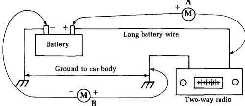
Fig. 2 Special techniques are used to measure the voltage drop in long
battery wires.
By doing these two tests, you can pin down the cause of any excessive voltage drop in the supply circuits. Don’t forget that these wires also go through switches and relays. To get away from possible voltage drops in automotive switches, most two-way radios and similar high-current equipment have relays that do the actual switching on or off; the car’s ignition switch is used only to control this relay. Make sure the supply circuit does not go through the ignition switch itself; such switches are too light for this purpose.
Identifying uncoded wires in multi-conductor cables
Identifying the wires in a large group of non-color-coded wires is difficult at best. You find this problem in intercommunication systems, where someone has bunched assorted wires without color-coding or identifying them. What do you do?
Get a 9V battery and a connection strip. Solder a pair of short test leads to the strip, with alligator clips at each end of the leads. You can hook a milliammeter in series with one lead, or use a pilot light (a 12 V type). This is shown in FIG. 3. Now all you need is a 0 V to 10 V dc voltmeter and a set of wire tags. Numbered adhesive strips are sold by many electronics suppliers for this purpose.
The testing takes two people. Find the two ends of the cable you want to identify. Put one person with the battery at one end, connect the battery to any two wires in the cable, and mark the negative wire NO. 1 and the positive wire NO. 2. At the other end of the cable, with your voltmeter, start checking between all possible pairs of wires for voltage. This is the hard part because you have so many possible combinations. If the wires have continuity, you’ll eventually find the right pair. Mark the negative wire NO. 1 and the positive wire NO. 2. To signal the person at the other end, short the two wires together a couple of times. If he’s using the pilot light, it will flash, indicating that you’ve found the first pair.
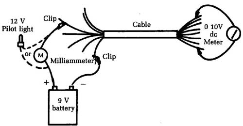
FIG. 3 A handy method for identifying uncoded wires in a multiconductor
cable. Clip; Cable
Your partner leaves the negative clip connected to the same wire (No. 1) and moves the positive clip to any one of the others. You leave your negative clip attached and search with the positive one until you find voltage on another wire. Mark this wire NO. 3; then short it to NO. 1 to flash the signal light. Your partner should have marked the positive wire NO. 3 while you were searching and now moves the clip.
This technique also serves as a good short or leakage test. Even after you locate the wire with voltage on it, check all the wires. See if you get a voltage reading on any of the others. You shouldn’t, unless there is water in the conduit, an accidental short, etc. If there is a short, this method will reveal it quickly. Your partner’s light will turn on the instant it’s connected to the shorted pair.
Testing capacitor leakage with a VTVM
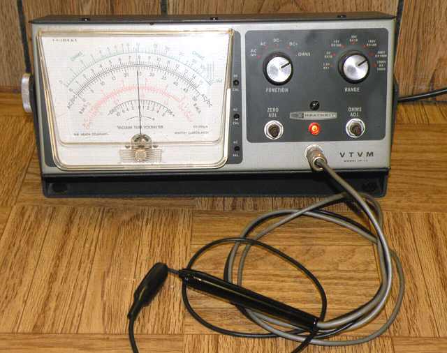
above: VTVM -- the Heathkit IM-13, measuring a 1 megohm resistor in its own
probe.
In checking small capacitors, find out if they are open, leaking, or shorted. Because of the way such capacitors are built, it’s almost impossible for them to change value. A 0.001 uf capacitor is likely to remain a 0.001 uF no matter what happens to it. Rather than check the value as with electrolytics, do a condition test to deter mine whether the capacitor is functioning. A leakage of as little as 200 to 300 M-ohm in a high-impedance circuit can upset things considerably, so it’s important to test for capacitor leakage when trouble occurs in these circuits.
A capacitor tester that has an insulation-resistance function is handy. All you need is a VTVM. Figure 4 shows how to do it. Disconnect the capacitor and hook one end to the dc-volts probe of the VTVM. Now touch the other end to any convenient source of V+ voltage. The actual voltage isn’t too important, as long as it’s about the same or somewhat higher than the voltage applied to the capacitor in the circuit. For large power-supply capacitors, especially in older tube equipment, about 200 V to 250 V is fine.
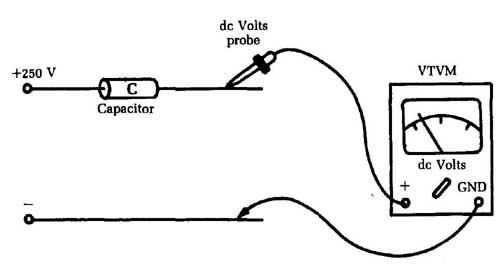
FIG. 4 A VTVM can be used to test capacitor leakage.
In modern solid-state (especially IC) circuits, much smaller capacitors are normally used, with rated working voltages of 25 V or even less. Don’t exceed the maximum rating of the capacitor under test or you could destroy it. For small, low-power capacitors, the ohmmeter battery in a VOM is sufficient. On the other hand, too low a test voltage might not give a readable result.
You’ll see an initial kick of the voltmeter, caused by the charging current of the capacitor. If there is little leakage, this initial deflection gradually will ease off and the meter needle will go back to zero. The larger the capacitor value, the longer this takes. If you’re in a hurry, you can touch the VTVM probe tip and ground with your fingers to discharge the capacitor faster.
Now, watch the meter needle. If it never reaches zero, or if it starts back up again after you have brought it to zero by touching the probe to ground as described, there is leakage in the capacitor. You’re making a voltage divider that consists of the input resistance of the VTVM and the capacitor. Leakage current gives a voltage drop across the meter—and a voltage reading.
The actual voltage isn’t too important; the fact that there is any voltage at all is what you’re looking for. In coupling-capacitor circuits, even a 1 V leakage can be too much. It causes a leakage of positive voltage from the plate of one stage onto the grid of the next stage, canceling out part of the negative bias voltage and per haps throwing the tube onto the wrong part of the curve and causing a severe distortion.
With transistors in similar circuits, capacitor leakage is even more important. It takes only a tiny fraction of a volt to make a transistor cut off or run wild. The latter can cause, overheating and avalanching, and can destroy a transistor quickly. For best results, check any new capacitor before putting it into circuit. Such a check can save a lot of time if the new capacitor does hap pen to have a little leakage! We have a tendency to automatically assume that a new part is good. This isn’t true in all cases; check first, and you’ll be sure.
Measuring very high resistances
You might have occasion to check high-value resistors that are far beyond the range of your ohmmeter scales. There is a way to do this—in fact, there are several ways.
The easiest is with a resistor of the same value or one as close as possible. If you don’t have an exact duplicate, you can connect several resistors together temporarily to get the necessary value. For example , for a bleeder resistor used in color TV focus-rectifier circuits—66 M—hook three 20 M-ohm resistors and a 6 M-ohm resistor in series; or use three 22 M-ohm resistors; etc.
For the test, connect the combination in series with the suspected resistor and connect the whole string across a source of voltage. The V+ voltage of the TV set is handy, but you can use any voltage, even the ac line if you want. Take a voltage reading across one of the resistors, as shown in FIG. 5, and note the reading. Next, check the voltage across the other resistor.
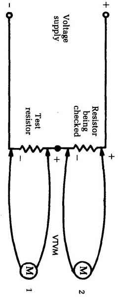
FIG. 5 Very high resistances can be measured using this method.
Because you have deliberately made a divide-by-two voltage divider, the two readings should be almost the same if the resistor under test is okay. If the difference is not more than 10 percent, the resistor is probably good. (The amount of difference you should tolerate depends on the resistors used; if they are 5 percent resistors, then cut down your tolerance to this amount, and so on.)
If you don’t have the right resistor values, you can still use some that will make the total resistance of the voltage divider come out at a value that is easy to interpret. For example, with the 66 M-ohm resistor, you could use a single 22 M-ohm test resistor. Your whole circuit would then offer 88 M-ohm (66 + 22); your voltage reading across the 22 M-ohm resistor would be one-fourth of the total voltage. If you used 200 V, you’d read 50 V across the 22 M-ohm and 150 V across the 66 M.
Note that this method takes the meter resistance out of the picture only if all resistors are equal. If you had to figure the actual voltage present across each resistor, you’d have to figure out the shunting effect of the meter resistance.
Checking diodes by the balance method
You can use the method described for checking very high resistances to also check diode back-resistance. You can check ordinary diodes, such as afc, video and sound detector, etc. with an ohmmeter, as will be shown in a later section. However, if you run into special units, such as the high-voltage diode rectifiers used in focus and boosted-boost circuits in color TV sets, the ohmmeter simply won’t reach the resistance range needed.
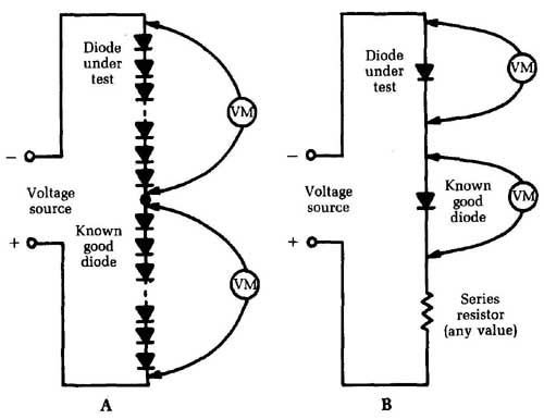
FIG. 6 Diodes can be checked with the balance method. Diode under test;
Voltage; Known source good diode; Series resistor (any value)
The duplicate-and-balance method shown in FIG. 6A is the easiest. Connect the suspected unit in series with another one just like it, and feed a voltage to the combination for equal voltage drops across the two units.
You also can use this method for testing low-voltage diodes and for checking balance on afc diodes, ratio-detector diodes, and diodes used in any of the circuits of FM multiplex receivers and decoders. With these low-voltage units, connect the diodes in series and add a series resistor to keep the current within safe limits (see part B of Fig. 6). Now hook a small test voltage across the combination and check the diode voltage drops for balance.
As a general rule, if any diode—from the 5,000 V focus rectifiers down to one of the tiny video-detector diodes — is really bad, the defect will show up in the front-to-back resistance ratio, which can be measured by this test. You can feed an audio or RF signal across the combination and read the result with an oscilloscope or a good ac VTM,
Checking video-detector diodes with an ohmmeter
You can check the small video-detector or signal diodes very accurately with an ohmmeter. A good diode shows a small resistance in one direction and a very high one in the other. The actual resistance readings seem to depend on the battery voltage used in the ohmmeter. The forward resistance varies with voltage and diode types but will probably be in the neighborhood of 100 to 200 ohms. The reverse-bias measurement should read several hundred thousand ohms.
Practically all VTVMs use a low-voltage battery in the ohm meter; the average voltage is about 3 V. Most VOMs use a 1.5 V battery on the low-resistance ranges, but use up to 22.5 V on the highest resistance scale in the megohm range. Diodes should be tested on low range—a scale of 0 to 2,000 or 0 to 5,000 — because such a range will use a low-voltage battery.
Find out which of your ohmmeter leads is positive; that is, which one is connected to the positive side of the ohmmeter battery. Check yours with another voltmeter and mark the positive lead. A voltmeter check also tells you exactly what voltages are used in your ohmmeter on various ranges.
If the positive ohmmeter lead is placed on the cathode of the diode and the negative on the anode, you get a high-resistance reading. Reverse the leads for a low-resistance reading. The ratio between the two should be very high for best performance in video detectors and similar circuits.
Actually you don’t have to bother with polarity. With a high resistance one way and a low resistance with reversed leads, the diode is okay. However, with an unidentified diode or one so small that you can’t tell what the markings are (not uncommon), use the ohmmeter to identify the elements. In the forward-bias direction, the positive lead is on the anode (triangle) and the negative is on the cathode (bar) of the diode. This test is illustrated in Fig. 7.
Checking video-detector diodes in-circuit with an ohmmeter
Whenever you run into a white-screen symptom in a TV and the cause is not an agc block or a dead IF tube or transistor, it could be a bad video-detector diode. These diodes are usually contained in a small can, and they shouldn’t be unsoldered and re-soldered too many times. You can make a definite and reliable test without moving a wire: the ohmmeter will tell you from outside whether the diode is good or bad.
Figure 8 shows a typical video-detector circuit. The IF signal comes to the diode from a secondary winding on the last IF transformer; the other end of the winding is grounded. (This is a series-diode detector, but shunt detectors can be checked in the same way.) The coils are peaking chokes, which give the circuit a wideband response, and the video-diode load resistor is the 3,300 unit connected from the diode output circuit to ground.
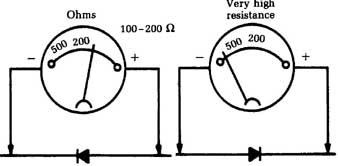 FIG. 7 This is a technique
for checking video-detector diodes with an ohmmeter. Ohms; Very high resistance.
Last video IF transformer.
FIG. 7 This is a technique
for checking video-detector diodes with an ohmmeter. Ohms; Very high resistance.
Last video IF transformer.
To check the diode, first hook the negative lead of the ohm meter to the video coupling capacitor, as shown. That way you can read the dc path through the peaking coils and diode to ground. The positive ohmmeter lead is connected to ground (1 in the figure). This is the reverse-bias direction, so you should read nothing but the load resistor plus the small resistance of the two peaking coils — actually, 3,318 (but if you get 3,300 , it’s okay.)
That’s one check. Now, reverse the leads—positive to the coupling capacitor, negative to ground (2 in the figure) — and read the diode in the forward-bias direction. Your path is through the low forward resistance of the diode with the 3,300 resistor in parallel, so the measurement should read something like 150 ohm. Simply ensure there is a good, high ratio between the two readings.
If the reading is infinity on both tests (no reading at all), the diode or one of the peaking coils is open. It doesn’t matter which; you’re going to have to take the circuit apart to find out which one and fix it. Check each of the coils for continuity before you de solder the diode; such coils sometimes open because of corrosion on the fine wires. If you have a coil shunted with a resistor — such as the last coil in the circuit shown, which is shunted by 8.2k-ohm — the value of the reading can tell you which coil to suspect. For ex ample, if you read 8.2k-ohm + 3.3k-ohm from grid to ground (in the high- resistance direction) you know the last coil is open, so check it
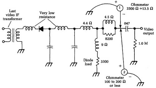
FIG. 8 A typical video-detector circuit.
If the reading is the same in both directions, and very low, the diode is shorted. You can figure what the correct resistance of the circuit should be by totaling the resistances of the peaking coils and diode load resistor, etc. If you have any doubts, you can lift the ground end of the diode load resistor, thus eliminating the shunt path, and read only the diode’s resistance.
In shunt detector circuits, where the diode is connected from the transformer output to ground, you can trace the dc path for the ohmmeter reading and catch an open or shorted diode in the same way.
Checking transistors with a VOM
The VOM makes a good transistor checker. It can be checked with an ohmmeter. Figure 4-9 shows the basis of the test.
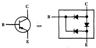
FIG. 9 A VOM can be used to check a transistor.
A good transistor reads like three diodes—base-emitter, base-collector, and collector-emitter—as shown. A good junction reads a high resistance in one direction and a low resistance in the other. The actual resistances will vary widely, depending on the battery voltage used in your ohmmeter, the type of transistor (silicon, germanium, etc.), and its rating. Look for the ratio be tween the two readings for each diode; this ratio should be high. Typical values might be 200 in the forward direction and 50,000 to 75,000 in the reverse.
Use the low-resistance scale on your ohmmeter, particularly in a VOM. This scale usually has a low-voltage battery (1.5 to 3 V) and won’t damage the transistor. The high-resistance (megohms) scale can use up to 22.5 V, which can damage low-voltage transistors.
To check each diode, take one reading and reverse the leads to read the resistance in the other direction. If the reading is the same in both directions (100 L or less), that junction is shorted. For a valid test, the transistor must be disconnected; there are often very low resistances, such as coils, low-value resistors, etc., connected across the junctions. If you get a reading of infinite resistance in both directions, the junction is open. This defect is fairly rare. If you read something like 100 one way and only about 500 L the other way, the transistor is probably leaking across that junction and should be replaced; a 5 : 1 ratio is too low.
Voltage and resistance tests
Voltage measurements in radio and TV work are helpful. They also can be misleading—that is, unless you know what you are reading, where you’re reading it, what you’re reading it with, and what the reading should be! Again, all tests are comparisons against a standard, and in the case of voltage measurements the standard is the operating voltages given on the schematic diagram.
In low-impedance circuits such as the power supply, you can use any kind of voltmeter. The circuit can supply so much current that the type of meter used makes no difference. However, when you get farther along in a piece of equipment into some of the high-impedance stages, the meter impedance plays a more significant part.
Figure 10 shows a good example—one of the popular tube circuits used in many older TV sets as a sync separator and agc stage. Note the values of some of these resistors. In some cases, you need to read a dc voltage through a resistance of 10 or 12 M. All of the coupling capacitors, etc., that feed signals into this circuit have deliberately been left out because you are only concerned with the dc voltage relationships in this type of circuit. However, the ac signal does make a great deal of difference, not only in the output, but also in the dc voltages themselves.
Yes, this is a complex circuit, but you can check it rapidly if you know what to look for and the meaning of what you see. The diagram shows a set of voltages on the tube elements. Suppose you take a set of readings with a VOM. They will all be different from the values called for on the schematic. Why? Because you didn’t read the instructions. Look in the corner of the schematic; it says very plainly, “dc voltages read with a VTVM.”
For instance, if you put a VOM on a 0 V to 100 V scale (20,000 per volt) and check pin 9, you won’t read 100 V as the schematic calls for. The meter resistance on this scale is 20,000 X 100=2 M. Look at the size of the dropping resistor —12 M-ohm If you shunt only 2 M-ohm from this point to ground, you load down the circuit so that the voltage drop across the 12 M-ohm resistor is far above normal. The result is a “wrong” voltage.
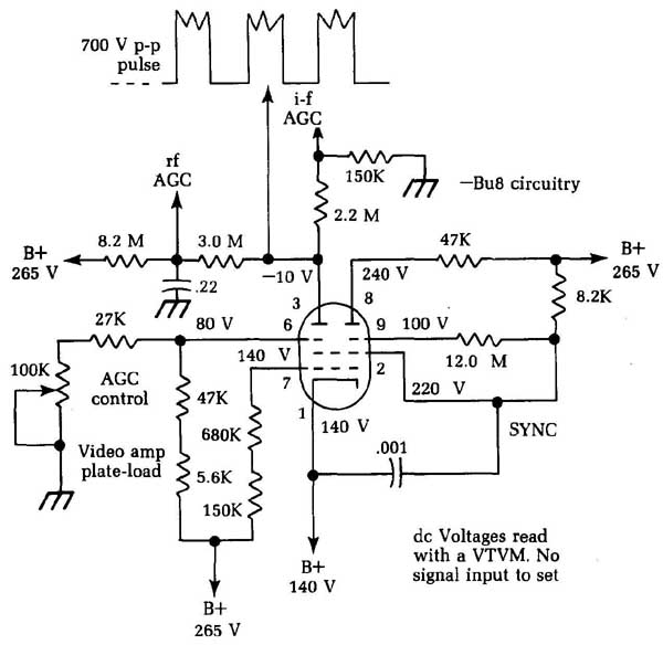
FIG. 10 One of the popular circuits used in a number of older TV sets
as a sync separator and agc stage. B+, 265 V; dc Voltages read with a VTVM.
No signal input to set
If you use a VTVM, with an 11 M-ohm input resistance, you get a reading that is closer to the actual voltage. In fact, you can read the exact voltage shown on the schematic because this is the type of meter originally used to read the voltage. So, all dc voltages should match those shown if you are using the type of meter specified on the schematic. Always check the corner of the diagram. Some have voltages that were read with a 20,000 ohms-per-volt VOM. In that case, all VTVM voltages should read higher than normal.
Some circuits call for voltages that are far different from what you might expect at first glance. Notice , for example, that there is a total of 11.2 M-ohm in series with the plate of the agc section of the tube that leads to the 265 V+. According to the schematic, how ever, the plate should read —10 V. Why? Because a positive-going keying pulse is fed to this plate at 700 V p-p from the flyback.
There are also resistors (2.2 M-ohm and 150k-ohm ) leading to ground in the IF agc circuit. The high pulse makes the tube conduct, and the plate-current flow through the load resistors makes that point negative when measured to ground. The positive voltage coming from the 265 V line through the very large resistors bucks out or balances some of the negative voltage, and you wind up with the correct agc voltage. (Part of this circuit also serves as a delay for the RF agc.)
There’s one other point that can fool unwary technicians. The instructions state clearly that these voltages were read with no signal applied to the set. Why? Well, if you check up on this circuit, you’ll find that there is normally a video signal voltage applied to the control grid. This signal controls the conduction du ration of the tube—the time when plate current is flowing. The tube normally is cut off by a high bias voltage, so it isn’t drawing plate current at all. When a signal fed to the grid reaches a certain value, current starts to flow, changing the voltages present considerably. Look at the monstrous resistors used; it takes only a few microamps of current to develop a large voltage across them.
Because there is no way of knowing what the actual signal input to the set would be, take the only possible standard: no signal input at all. You’re now taking voltage readings under the same conditions they were taken at the factory.
Voltage and resistance circuit analysis
In actual field servicing, operating voltages provide your best clue to trouble by changing from the normal (becoming either too low or too high). Whenever you find a tube or transistor with an incorrect voltage on any of its elements, check the complete circuit to find out why. After the voltage analysis, turn the set off and make a resistance check of all parts in the path in question, all the way back to the supply point.
For a typical example, refer back to Fig. 10. Suppose that either the 8.2 M-ohm or the 3 M-ohm resistor has increased in value. This occurrence would reduce the positive voltage on the plate of the tube, making the plate go too far negative. This in turn would make the agc too negative, and the controlled stages would be cut off—an agc whiteout. If the 0.22 uF bypass capacitor leaked, a low-resistance shunt path at the junction of the two large resistors would be added. Once again, there would be too little positive voltage to balance the circuit, and the same symptoms and a whiteout would occur.
How do you pin down the faulty part in such circuits? Mea sure the values of all resistors in the path where the fault might be. If there is too much negative voltage at the agc plate and too much positive voltage at the junction of the 8.2 M-ohm and 3 M-ohm resistors, but the 265 V supply checks normal, then suspect the 3 M-ohm resistor of being open or greatly increased in value. If there was too little (or no) voltage at this junction, suspect the 8.2 M-ohm resistor of being open.
To get a correct reading of these resistors, open the circuit. Lift one end of a resistor before making any resistance measurements across it. To read the exact value of the 2.2 M-ohm filter resistor from the plate to the IF agc, lift one end of the 150k-ohm shunt resistor to ground. If you do not, there would be at least two paths: one through the resistor and the 150k-ohm resistor to ground; the other, back through the big resistors to B+, which usually measures about 20,000 12 to ground because of the leakage resistance of the electrolytic filter capacitors.
Transistor circuits
In transistor circuits, you have the same basic problem with shunt paths, but with very low resistances. Figure 11 shows a typical class-A amplifier stage with an npn transistor. You might find such a stage in the preamplifier circuits of a hi-fl audio amplifier or in some similar type of equipment.
The signal here is developed across the load resistor, RL. This resistor is of such a size that half the supply voltage will be dropped across it, and the plate current can swing above and below the operating point an equal amount; this is what makes it a class-A stage. With an 18 V supply, there’s a 9 V collector potential measured to ground. (If this were a pnp transistor, it would be the same thing, but the collector voltage would be negative.)
Notice the voltage divider network, resistors R1 and R2. They are proportioned so the base will have the right bias voltage for the type of transistor used—here, 0.69 V. But the schematic says very plainly: 1.69 V! The emitter is 1 V above ground, so the actual base-emitter voltage is 1.69 -1.0 = 0.69 V.
In the tube circuit of Fig. 1, recall that both the grid and cathode of the tube read 140 V from ground. What is the actual grid-cathode voltage? That’s right: 140 — 140 = 0! In case you were wondering about the statement that the tube is normally cut off, look at pin 6. This pin is a second control grid in this type of tube and actually has a -60 V bias: 80- 140 = -60.
In such circuits, there are shunt paths again. You can’t read the resistance of either R1 or R2 correctly unless you open the circuit. The resistance of the base-emitter or base-collector junction is in parallel with these resistors. Take out the transistor or lift one end of the resistor to get a correct resistance reading.
If the voltages are off-value in such circuits, don’t try to pin the trouble down by doing in-circuit tests with an ohmmeter. Break the circuit up into small sections and check each part by it self. Wrong bias on the base of the transistor could be caused by a shorted transistor or by incorrect values on R1, R2, or even RE.
The voltage-resistance test sequence is probably the most useful in any kind of electronics work. Properly applied, it can give you a great deal of information in the least possible time. Using improper methods can lead you farther away from the real trouble. The nonexistent defects aren’t faults at all, but simply in correct indications caused by the wrong test equipment!
In general, find the defective stage by signal tests, then check its operating voltages. If any is off value, turn the set off and find the cause of the incorrect voltage by tracing the supply circuit back to its source. Measure all resistors in this path, including the resistance of coils, chokes, and anything else that is a part of the dc path back to the supply. Learn to trace out a circuit and follow it back to the source of power. Start at this point, making sure the source voltage is correct for the very first test. You would be surprised to know how many technicians overlook this obvious and extremely simple test! By beginning at the supply and following the circuit until you come to an abnormal indication, you can pin down the trouble in the least possible time.
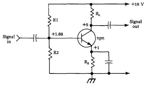
FIG. 11 A typical transistorized class-A amplifier stage. Signal out;
Signal in
==Stacked stages==
Circuit with stacked stages have confused many technicians be cause of the unusual dc voltage relations. The term stacking refers to the dc voltage distribution between the two (or more) transistors. The circuit shown in FIG. 12 is used in a commercial stereo amplifier and is a section of only one channel. It’s a direct- coupled driver and output-transformerless (OTL) output stage. The circuit works in class B, with one transistor handling the positive half-cycles and the other handling the negative. The speaker is connected to their midpoint and ground.
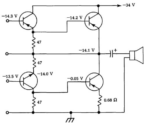
FIG. 12 This stacked transistor circuit is from a commercial stereo amplifier.
Notice that the maximum power supply voltage is connected to the collectors of the upper transistors and that the emitter of the upper output transistor does not go to ground, but to the collector of the lower transistor. The emitter of the lower transistor is connected to ground, which is the positive point of the power supply. (Remember, in any transistor circuit, the polarity of the power supply is determined by the type of transistor used — npn or pnp.) You can have a supply voltage of —34 V for one type or +34 V for the other and it’ll work out the same. The main interest now is in the proportion of the supply voltage taken by each transistor because this proportion tells if the circuit is working properly.
Notice that the voltage does not split in the middle, as it usually does when similar vacuum-tube stages are stacked. Maxi mum supply voltage is —34 V, but the midpoint of the circuit has only —14.1 V. The midpoint value must be checked on the schematic so you know what is correct.
Incidentally, transistor circuits don’t have the rather wide voltage tolerance that most tube circuits have. If the schematic specifies 14.1 V, it doesn’t mean 14.3 or 13.8—it means 14.1 V. In most transistor circuits, a change of only 0.2 V can cut a transistor completely off or drive it to full conduction and overheat the junction.
Learn to measure these very small voltages with extreme care. Measuring the collector current is a very good way to check the bias voltage. There is a much greater meter deflection, and it’s usually easier to read on shop-type equipment.
Troubles in circuits like these are the same as in other stacked circuits: resistors that have changed in value, transistors with leakage between elements, inter-element shorts, etc. The emitter-base voltage (the bias) is a good place to start measuring if you suspect trouble. Use a sensitive and accurate VOM. A digital meter would be helpful here. Read the voltage directly from emitter to base. If this voltage is intolerance, the transistor is probably okay. If it’s off by more than 0.2 V, then there is very likely something wrong in that stage.
Note the direct coupling used in the driver transistors (the left-hand pair in FIG. 12). This is a very common circuit and has the same type of voltage distribution as the push-pull circuit. The available supply voltage will divide between the two in a ratio determined by the type of transistor and the bias on each one. Consult the schematic diagram of the circuit you are working on to verify the correct voltage.
Bad base bias
In many transistor amplifier stages, a specific bias voltage will be applied to the base, regardless of the input signal. In most servicing schematics, the desired normal bias voltage will be given. Un less otherwise noted, this bias voltage value assumes that the stage’s input signal is 0. For testing purposes, it’s often useful to ground the input to the amplifier stage to ensure a zero signal.
Figure13 shows the basic circuitry for a typical single- transistor amplifier stage. You will find this circuit (or a variation of it) in a great many electronic devices of all types.
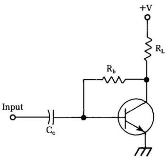
FIG. 13 The basic circuit for a typical single-transistor amplifier stage.
With a zero (grounded) input, simply measure the base bias voltage by connecting your voltmeter between the base of the transistor and circuit ground. You should get the value given in the schematic or other troubleshooting literature for the equipment being serviced. If this voltage is off, the first thing to suspect is the supply voltage. (The tolerable error will depend on the in tended application and the precision required for the particular circuit you are working on.)
If the supply voltage is okay, check the transistor’s collector. If this value is way off the nominal value (from the schematic or servicing literature), you might have a bad transistor. Refer to section 8 for information on testing transistors.
Assuming the transistor’s collector voltage is okay, but the base bias voltage is incorrect, there are two likely possibilities: either the coupling capacitor (C in Fig. 13) is leaky or there is some unintended leakage resistance between the transistor’s collector and base. This leakage resistance might be internal or external to the transistor itself.
To narrow down the cause of the problem, it’s usually easiest to check out the coupling capacitor for leakage first. To do so, make sure the input to the amplifier stage itself is not grounded. The input to an earlier stage in the circuit can be grounded if necessary to force a zero input condition. Now, monitor the transistor’s base voltage as you short-circuit the input end of the capacitor to ground. If the measured voltage changes, especially if by a large amount, then the coupling capacitor is almost certainly leaky and should be replaced. On the other hand, if there is no effect on the measured base voltage, the capacitor itself is probably not the source of the problem in the circuit. The defect must be collector-to-base leakage of some sort.
Unfortunately, it takes a little more effort to trace a collector- base leakage problem because you must do some desoldering. Disconnect one end of the base resistor (Rb). It would probably be a good idea to check out the resistance of this component with an ohmmeter while it’s disconnected. If this resistor has somehow changed value significantly, it could be the cause of the problem.
To test the transistor for internal collector-to-base leakage, monitor the collector voltage (from the transistor’s collector to circuit ground). Now temporarily short together the base and emitter of the transistor. If the transistor is good, the collector volt age should jump up to the full supply voltage. (Don’t be misled by any circuit resistances between the actual power supply and the transistor’s collector.) If the measured collector voltage with the emitter and base shorted is less than the expected supply voltage, then the transistor is internally leaky. Replace it.
Dealing with noise pick-up
If you are working in an area with very strong electromagnetic signals, such as radio waves, or if very high level signals are used in one part of the circuit you are working on, you might find your self plagued with noise pick-up problems when you attempt to take measurements. The test probes and leads can act like antennas, picking up any strong nearby electromagnetic signal. Such unwanted signals also can sneak in through ac power lines.
This unintentionally picked up noise signal will be added to the signal you are attempting to measure. If the interfering signal is quite strong and the signal you are trying to measure is small, the desired signal might be completely engulfed and lost in the noise. Obviously, you can’t get an accurate, or even a meaningful, measurement under such conditions.
Battery-powered test equipment tends to be somewhat less prone to such noise pick-up problems. When you encounter this type of trouble, switch over to battery power if possible. Disconnect the ac adapter. This action will reduce line induced noise, which is one of the most common sources for this type of problem.
If you must use ac power for your test equipment, or if switching over to battery power doesn’t sufficiently clear up the problem, try connecting a 0.1 uF capacitor across the multi meter’s input jacks. This solution usually will filter out the picked up noise signal quite well. For best results, use a polyester capacitor, or something similar.