AMAZON multi-meters discounts AMAZON oscilloscope discounts
Current measurements aren’t as simple to make as voltage measurements. The meter must become part of the circuit instead of touching across it, which takes more time. Also, you have to be very careful—picking the wrong current range or shorting the load to ground accidentally can blow a meter very quickly. For this reason, many technicians are reluctant to use current tests. However, current measurements can give a great deal of information about a circuit in a short time. With reasonable care, there is no more risk of meter damage in this test than in any other.
You can make the job of getting the meter into the circuit much easier with some special equipment. Test adapters of various types allow current measurement by plug-in testing without unsoldering wires. Some types of adapters can be bought ready- built, but you might have to make a few. They’re well worth the little time it takes in terms of bench time saved.
Reading the input current drawn by any electrical apparatus can tell you the total wattage being consumed; simply multiply the current by the applied voltage. The actual wattage consumed is a valuable piece of information because the rated wattage is al most always given in the service data for the apparatus. If a device is taking more power than it should, there is definitely something wrong—a leakage, a short circuit in the power supply, etc.) By measuring input current you can, For example, check a power transformer for an internal short.
The input current test works on ac and dc equipment, all the way from a tiny transistor radio to a 5,000 W transmitter. Current measurements within a circuit are essential in transmitter testing and in all kinds of high-power work such as PA systems and high- power amplifiers. In high-power transistor amplifiers, a current measurement can tell you if transistors are leaky, indicate whether bias voltages are correct, and give you other useful information.
==Power measurements==
If a TV set, amplifier, etc., becomes too hot as it plays, you need to know if it’s actually drawing too much power, and if so, why. The input wattage measurement of any piece of ac-powered equipment is a very good clue to what’s going on. You can check the actual power being consumed to pin down a short or leakage in the power supply circuits, or even an open circuit—one that isn’t drawing as much power as it should.
The watt is a unit of power that is always a product—volts multiplied by amps. So an ordinary voltmeter or ammeter won’t read power— you have to take simultaneous voltage and current readings and then do the math. Of course, there are wattmeters that will do this for you. They’re actually combination volt- ammeters, having a current coil in series with the line and a volt age coil across it. Both coils affect the position of the meter needle: the amount of deflection depends on the product of the currents in the two coils, so the scale can be calibrated directly in watts (see Fig. 1)
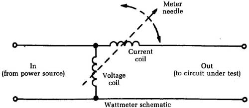
_ Fig. 1 The current through the two coils affects the amount of pointer
deflection. Meter needle; Current coil / Voltage coil; In(from power source)
/ Out(to circuit under test); Wattmeter schematic
There are many uses for this instrument. However, watt meters are not commonly found in service shops because they are fairly expensive. Some shortcut tests can give the same information but use more common test equipment. Any of the wattage tests discussed can be made accurately with the three substitute testers described later.
==Measuring the dc drain of an auto radio==
Measuring the current drain of an auto radio is probably the simplest current test. All you need is a 0-to-10-amp dc ammeter, connected to one of the power-supply leads to the auto radio, as shown in Fig. 2. The rated current drain for the specific set should be in the service data.
Transistor equipment generally draws a relatively low amount of current, usually under 1 amp at 12 V. Older tube sets with vibrators drew considerably more current. Drains as high as 8 to 12 amps were uncommon. Some early hybrid models that used tubes for the early stages and transistors in the output stage had current ratings in the 1- to 1.5-amp range.
If you use an ac-powered bench supply for operating auto radios for test, the supply will probably have a dc voltmeter and an ammeter built in. If not, you probably can use your VOM for the ammeter; such meters usually have a dc range of 10 amps or so, which is ample for most auto radios. Be sure that the supply voltage is set to the state level because this affects the current drawn and the wattage.
If the tone of an auto radio is not as good as it should be and the current is either more or less than the rated value, check the bias on the output transistor(s). The output stage causes the heaviest current drain of the whole set.
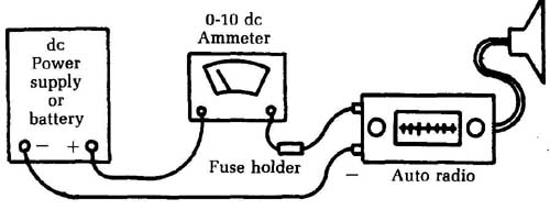
_ Fig. 2 An ammeter can be connected to one of the power-supply leads
of an auto radio.
==DC current measurements in transistor portable radios==
Current measurements are invaluable in servicing small transistor radios, particularly the subminiature types. Because of their small size, it’s hard to get into these circuits. So, we take current readings, which we can do from the outside, and get all the information possible before we start taking things apart.
Practically all the bench power supplies used for testing these radios have a dc milliammeter as well as a dc voltmeter. If yours doesn’t have one, you can always use the 0- to 25- or 0- to 50-mA range of the VOM, as in Fig. 3.
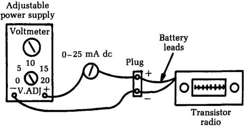
_ Fig. 3 A VOM can be used to monitor the current supplied by a bench
power supply. Adjustable power supply; Voltmeter; Transistor radio; 0 to
25 mA dc
A set of connector harnesses can speed up the work. Take the battery terminals from a dead battery and solder a set of test leads to them, watching polarity. Now, when working on a radio using this size battery, you simply snap on the connector. It’s handy to have a harness for each of the common sizes of batteries.
A set of test leads with alligator clips is very useful. For example, you can use them to connect a milliammeter in series with the radio battery by turning the battery plug sidewise and clip ping on, as in Fig. 4.
If the radio uses penlight batteries in holders, you can get your meter into the circuit with an adapter like the one illustrated in Fig. 5. Get a strip of heavy insulating paper (such as the fish paper used in electrical work) about ½ inch wide and 2 to 3 inches long. Cement a thin strip of brass (shimshock) to each side, and solder test leads to the ends of the strips. Be sure the brass strips are cut a little smaller than the insulator. To use this adapter, insert it between any two batteries in the string and connect the test leads to the milliammeter. It’s easy to get the adapter in place if you lift the ends of the two of the batteries, put the adapter be tween them, and then push them back into the holders.
Check the service data to determine what the current drain should be. In a typical six-transistor portable, it might run less than 10 mA at minimum volume and about 15 mA to 20 mA at full volume. Maximum current depends on how much audio power output the set has.
There are many uses for the input current test in addition to checking bias, battery life, etc. You can even use it as an alignment indicator. The total current drain of a transistor radio depends on the audio output; if you use an audio-modulated signal for alignment work, the current drain will be directly proportional to the amount of audio signal. So feed in an IF or RF signal and tune for maximum current. The volume control can be set to give a convenient amount of current. This setting and that of the RF signal generator output shouldn’t be changed during alignment unless the signal becomes too high and threatens to over load the receiver or cause clipping.
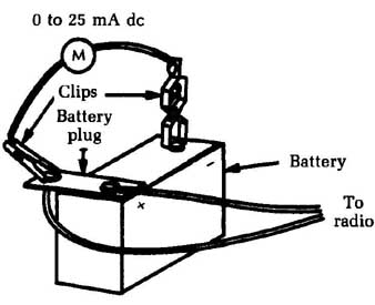
_ Fig. 4 Test leads with alligator clips can be very useful. To radio.
Battery
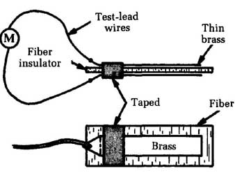
_ Fig. 5 This adapter can be employed to use a meter with a circuit powered
by penlight batteries.
==Testing power transformers for internal shorts==
Many sets have “hot” power transformers. They might smell bad, have tar running out, etc., and in general show all the symptoms of being hopelessly burned up. But are they? The big question is always this: “Is the transformer broken down internally, or is the overheating a result of a short in the load circuits?” In all cases, you must know if the transformer itself is bad before you can make any estimate on the job. So, check it first.
Remove the rectifier tube or disconnect the silicon rectifiers, etc. In a few sets, you can do this by pulling the V+ fuse. In any case, be sure that the rectifiers are completely disconnected from the power-transformer secondary.
In a tube set, you should open the filament circuit by disconnecting one wire from the power transformer. ( You could pull all the tubes, but that takes longer!) If the filament circuit is center- tapped, you’ll have to open both supply wires. In all tests, make sure that there is no load on the power transformer.
Plug the primary of the power transformer into the watt- meter and turn it on. If the transformer is not internally shorted, you’ll see a very small kick of the meter needle as the magnetic fields build up, and then the reading will fall back to almost zero. This reading, usually 2 W to 3 W at most, is the “iron loss” and is normal. If there is a shorted turn anywhere in the transformer, however, the wattmeter needle will come up to 25 W or 30 W. If the short is in one of the high-current windings, you’ll see a full scale, needle-slamming reading, which means that the transformer is definitely bad. Recheck to make sure that all loads have been disconnected. (Even two pilot lights can show a reading of about 5W).
There is also a no-instruments-at-all test you can do on a power transformer. Hook up the transformer with no load on it, and leave it on for 5 to 10 minutes. If the transformer gets too hot, it’s bad. A good transformer will get just barely warm running no- load. A badly shorted one will heat up and smoke.
==Substitute power testers==
Let’s discuss the kind of equipment you can substitute for a watt- meter to get the same results. Since you need a “volts times amps” reading, you have to do your own arithmetic. The ac line voltage is usually specified as being 117 V rms, but let’s use 120 V for simplicity. If you know the line voltage, measure the current and get watts by multiplying. For example, if the rating plate of the equipment under test reads 240 W your current should measure 2 amps.
You can use a 0-to 5-amp ac ammeter ( Fig. 6) of the panel- meter type for such measurements. Also, an adapter is available that makes a clamp-on ammeter out of a pocket VOM. It has a current transformer made so that the core can be opened up and clamped around either one of the ac wires. When the adapter is in place, the meter reads ac current on the ac volts scale.
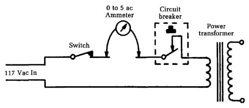
_ Fig. 6 A 0 to 5-amp ac meter in series with the input can be used to
mea sure wattage. 0 to 5 ac; Ammeter; Switch; 117 Vac In; Circuit breaker;
Power transformer; 0 to 5 ac Voltmeter
If you have one of these adapters ( Fig. 7), be sure to place the clamp-on core around only one of the wires; if both wires get in side it, you won’t get any reading. On TV sets, you can usually get at one wire at the ac interlock, at a wire going to the switch, etc. You can now read current, multiply it by line voltage, and end up with the wattage.
However, ac ammeters aren’t common in service shops either. Let’s figure out another way to measure power. Use the ac voltmeter from the VOM. Get a fairly accurate 1 resistor; the standard 5W or 10W wirewound types are an “automatic” Ohm’s law computer. Using E = IR, Ohm said that for every ampere of current that flows through a 1 resistor, it drops 1 V across it. So, you can read the ac voltmeter as an ac ammeter. In a 240 W circuit, you’d read 2V (and therefore 2 amps) and get the same result as before. This technique is illustrated in Fig. 8.
The method just described is a valuable test for sets using small circuit breakers in the primary of the power transformer. If the breaker kicks out at odd intervals, check to see whether it’s caused by an intermittent overload in the secondary circuits or to an intermittent breaker. The kickout value of current is always specified on the breaker itself. For example, a typical unit might be rated “hold 2.2 amps; open at 2.5 amps.” If you read the actual current in the circuit and find that the breaker is kicking out at 2.2 amps, replace the breaker and that usually fixes the trouble!
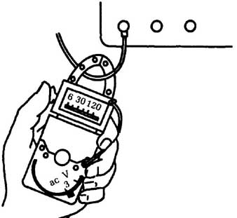
_ Fig. 7 This adapter permits ac current to be measured on the ac volts
scale.
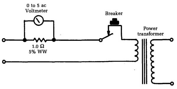
_ Fig. 8 Ohm’s law can be used to measure ac current on the ac volts scale.
Breaker; 1.0 ohm, 5% 0.25W, Power transformer
==Finding overloads in power supplies==
After clearing the power transformer from suspicion in a fuse- blowing or overheating problem, you can put the loads back on one at a time and find out which one is faulty. One good test is to leave the filaments open and hook up only the V+. Check input power again. If it shows more than 30W to 35W, look out! If the current drain is as much as 75W to 100W with only the B+ circuits hooked up, there is definitely a short circuit in one of the branches.
Leaving the filaments off will raise the V+ voltage by taking off the normal loading. This test also can help to break down leaky parts and give you a nice, definite indication, such as a thin pillar of smoke. So do this test with care and with one hand on the switch!
If the transformer and V+ filter circuits check okay, you can read the V+ current drain by hooking a 0 to 500 dc milliammeter into the V+ filter output, as in Fig. 9. The normal current drain will always be given on the schematic; for example, 350 V, 260 mA—and so on. If you get something like 300 V at 290 mA, look out. Something is drawing more than its normal current.
The excessive current can be traced by voltage readings in individual circuits, especially if they have their own individual dropping resistors. Look for the resistor with the greatest percent age of drop. For instance, if you have taps for 350 V, 250 V, and 150 V coming off the V+ filter output, and the 350 V and 250 V lines read about 10 V low while the 150 V line reads about 50 V maximum, the trouble is in the 150 V line. For a quick check, disconnect the 150 V line and see whether the others jump back up to normal (or probably a little above because of the reduced loading). Having traced the trouble to a single circuit, you can chase down the short with an ohmmeter.
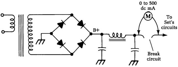
Fig. 9 A 0 to 500 mA milliammeter can be used to detect overloads in
the V+ filter output. To Set’s circuits; Break circuit
==Setting the bias of a power transistor with a current meter==
Transistor bias voltages are crucial. A change of only a small fraction of a volt can cause a transistor to cut off completely or draw a very high current—often enough to overheat the junction and destroy the transistor. If you suspect that a power transistor is drawing too much current, the only way to check it’s to insert an ammeter and read the current directly.
Fig. 10 shows this situation on a typical single-transistor output stage. The bias is adjusted by means of a series resistor in the base return circuit. Open the bottom of the output transformer primary circuit, as shown, and insert a 0- to 1-amp dc meter. With this connection, read the collector current; it value is determined by the base bias. ( You can consider this as either a voltage bias or a current bias; if you change current, you change voltage and vice versa, so don’t be confused about it.)
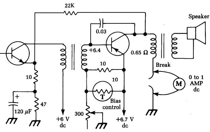
_ Fig. 10 This circuit illustrates a method for setting the bias of a
power transistor
with a current meter.
The circuit shown happens to be from a 6.3 V radio, and the power output is not very high. The rated values for this circuit are as shown, and the bias control should be adjusted to give a collector current of 550 mA to 600 mA (0.55 to 0.6 amp).
The collector goes directly to the ground through the primary of the output transformer. This winding has a very low dc resistance, so a dc voltage measurement here would be hard to read unless you had a meter that read millivolts. This explains why you take a current reading, which has more readable values. The actual current will be different on other sets, but the principle is the same.
For a given auto radio, details on how to adjust the output current are in the service data. Check this data before you make the test because auto radios differ in current values. The current in a given circuit depends on the type of transistor used and the way the circuit was designed. You need the exact value so you can adjust for correct current in the set you are working on. The bias value sets the operating point of the transistor.
In two-transistor push-pull or transformerless output circuits, correct collector current is especially important. Most of these circuits work in class B: one transistor amplifies the negative half of each cycle; the other, the positive. If the bias isn’t exactly right, you get what is called crossover distortion at the point where one transistor stops conducting and the other starts. Notice this distortion with a scope; there will be a decided break or notch in the signal waveform where it crosses the zero line. Some sets use a combination bias — the output stage actually works in class A on small signals, shifting to class B on large ones. Bias is very important on these circuits. Combination-bias circuits are also found in hi-fl stereo amplifiers and are adjusted in exactly the same way as car-radio circuits.
==Measuring large currents==
For most modern electronics work, you will be dealing with fairly small currents, usually in the milliamp range. (One milliamp equals 0.001 ampere.) Rarely will you encounter currents of more than 1 or 2 amps, but there are exceptions in some types of equipment.
Most multimeters aren’t designed to handle relatively large current measurements. The highest current range on many multimeters is only about 500 mA (0.5 amp), especially on less ex pensive models. But what if you need to measure a large current value, say 12 amps? You’ll only peg the meter’s needle at the high end of the scale. You won’t get a useful reading, and you might possibly damage your multimeter.
You can increase the range of any milliammeter (or ammeter) by adding a shunt resistor in parallel with it, as illustrated in Fig. 11. This trick works because of Ohm’s law, which states that:
I = E/R
where I is the current in amperes, E is the voltage in volts, and R is the resistance in ohms.
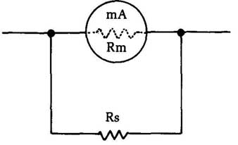
Fig. 11 The range of a milliammeter can be increased by adding a small
shunt resistor in parallel with the meter.
The total effective resistance in this case is equal to:
[…]
…where Rm is the internal resistance of the milliammeter, and R is the added shunt resistance. The total effective resistance (Rt) is always less than either of the component resistances in the combination (Rm or Rs).
As an example, let’s assume the internal resistance of the milliammeter is 30 ohm and a full-scale reading is obtained with a current of 0.5 amp (500 mA). This will occur when the voltage source equals:
E = IR
= 0.5 x 30
=15V
We want to extend the range of the meter to 5 amps (5,000 mA). The meter itself can’t handle more than 500 mA, so the remaining 4.5 amps must be carried by the shunt resistor. What should its resistance value be?
In a parallel combination, the same voltage will pass through both individual resistors. We already know that a supply voltage of 15 V gives the maximum current through the meter. We know the supply voltage (15 V) and the desired current (4,500 mA) to be carried by this resistor, All we have to do is to rearrange Ohm’s Law to solve for the unknown resistance:
R=E/I
= 15/4.5
= 3.3333 Ohm
Using a 3.3 shunt resistor will increase the milli-ammeter’s range by a factor often. Notice that the value of the shunt resistor is typically very small. The greater the desired increase in the meter’s range, the smaller this resistance must be.
This is all well and good, but it assumes you know the internal resistance of the original, unmodified milliammeter. What if this information is not readily available? You can’t measure this resistance directly with an ohmmeter.
A solution to this problem can be found with the test rig circuit illustrated in Fig. 12. This test circuit will work fine for either a bare milliammeter or the milliammeter section of a multimeter. Use 10K (10,000 ohm) potentiometers for R1 and R2. Resistor R3 is simply a protective current-limiting resistor, and its exact value is not terribly crucial. Use a 4.7K (4,700 ) or 3.9K (3,900 ) resistor, or anything you happen to have available in this approximate range.
Start out with potentiometer R1 set for its maximum resistance (lowest current flow) and switch Si open. At this point potentiometer R2 is not actually part of the circuit. Slowly decrease
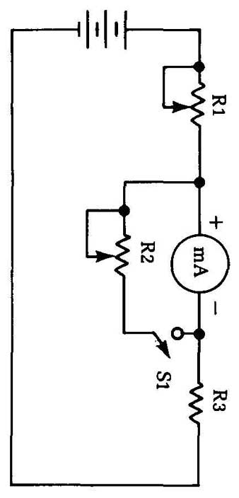
Fig. 12 This test circuit can be used to determine the internal resistance
of a milliammeter.
the resistance of potentiometer R1 to increase the current flow through the circuit, and therefore the reading on the milliammeter. Keep going until the meter shows its full-scale reading. Now, leave potentiometer R1 set as it is. Don’t move it.
Close switch S1 to add potentiometer R2 to the circuit in parallel with the meter’s internal resistance. Adjust potentiometer R2 until the meter gives an exact half-scale reading. At this point, the two parallel resistances (R2 and the meter’s internal resistance) must be equal. Being careful not to change the setting of potentiometer R2, open switch S1 and use an ohmmeter to measure its resistance. The milliammeter’s internal resistance has the same value as you read across this potentiometer.
Also see: Component tests