AMAZON multi-meters discounts AMAZON oscilloscope discounts
.
This section includes a variety of unique tests that require special techniques with common equipment.
Measuring peak voltages without a voltmeter
Frequently, you need to know the peak to peak drive signal volt age on horizontal output tubes, vertical output tubes, oscillators, etc. Normally, you read this voltage on a calibrated scope or with a peak to peak reading ac voltmeter. If these instruments aren’t available, however, you can always use the low-milliampere range or the microampere range of the VOM.
Open the bottom end of the grid resistor and hook the microammeter in series with it. Connect the positive terminal of the meter to ground and the negative terminal to the resistor. With the circuit in operation, multiply the current you read by the value of the grid resistor. The result, according to Ohm’s law, is the peak value of the grid voltage. Note that we said peak, not peak to peak; the grid conducts current only on the positive-going halves of the drive signal. So, to get the peak to peak value most often specified in service data, double the value calculated.
In one actual test, a 6DQ6 tube with a 470K grid resistor read a bit over 100 uA. This gives 47 V peak; the signal, measured with a calibrated scope, was about 90 V peak to peak. Resistors in such circuits aren’t precise; tolerances are 10 to 20 percent. Voltages obtained by this method won’t be exact, but they will be accurate enough to give the information needed pertaining to the drive signal voltage. Remember to double the reading for a peak to peak value.
Using a pilot lamp for current testing
When you encounter one of those jobs that runs along fine then suddenly blows the fuse, it can be expensive as well as annoying. Fuses cost money, especially if you blow four or five of them before you find the short. Make up a test adapter with a pilot-light socket wired across a blown fuse, as shown in FIG. 1. Use a pilot lamp that has a rated current a little higher than the normal drain of the circuit.
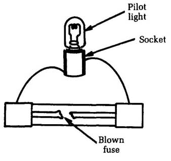
FIG. 1 A simple pilot lamp can be used for current testing. Socket; Pilot
light, Blown fuse;
For instance, if you’re checking the B+ supply of a TV set rated at 200 mA, use a 250 mA pilot lamp — No. 44. There are pilot lamps with current ratings all the way from 150 mA (No. 40, No.47) to 0.5 amp (No. 41, etc.). There also are special lamps rated as low as 60 mA (No. 49) if you happen to need them.
When you turn the set on, the pilot lamp will glow a medium yellow. You can watch this while you tap, move, heat, or test parts in the circuit. If you hit something that is causing the short, you’ll see the lamp flare up to a bright blue-white. A dead short will blow the lamp out, of course, but pilot bulbs are usually cheaper than slow-blow fuses!
As a matter of fact, Motorola and other two-way radio manufacturers have used pilot lights as B+ fuses in power supply for several years. If you run into one of these circuits, be sure to use the same type of lamp as a replacement; it must have the correct current rating.
A voltage divider for obtaining very small audio signals
For audio-amplifier testing, you need a source of low-level signals. Be very careful not to overload the input, in transistor amplifiers especially. Also, you can make a quick check on any audio amplifier by feeding in a given number of millivolts and measuring the audio-output power. If the amplifier comes up to specifications, there’s no need to go any further. This is also a fast way to isolate a weak channel on a stereo system.
You can read the output of an amplifier in watts by substituting a load resistor of the proper value for the speaker, applying a steady signal to the amplifier’ input, and measuring the voltage across the load resistor. The value of power output can be figured out by the Ohm’s law equation W = E In many cases, the right values of voltage for both input and output are given in the service data.
For instance, an amplifier might call for 2.75 V across the out put-load resistor at an input of 300 mV. The problem is to get a true 300 mV since most shop-type audio generators don’t have accurately calibrated attenuators. To get the signal needed, use a simple resistive voltage divider, as shown in FIG. 2. If the upper resistor has a value of 700 and the bottom resistor is 300 and you apply exactly 1 V of audio signal, you can take off 300 mV at the tap.
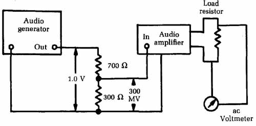
FIG. 2 A simple resistive voltage divider can be used to bring the signal
down to the desired level. Load resistor; ac Voltmeter
It might be more convenient to use a 1,000 ohm variable resistor, as in FIG. 3. Hooked up as a potentiometer, the slider can be set with an ohmmeter to give any value of signal output needed.
Stereo and hi-fl amplifiers designed for low-output magnetic cartridges usually call for about 5 to 10 mV, while “ceramic” inputs call for 700 mV to 1 V. With the signal-generator output set at a given level, the pot can be used to obtain any fraction of this amount. This method eliminates the need for accurate measurement of very low signals; all you need to know is the total signal across the divider and the way the divider is set up. A carbon potentiometer is best. The inductance of a wirewound pot could affect the accuracy of division at high frequencies.
A quick test for audio power output
There’s a quick and dirty test for audio power output if you don’t want to bother with calibrated resistors. Get a weatherproof lamp socket and put a couple of heavy terminal lugs on the wires— spade lugs are best. Connect this socket across the high-impedance output taps on the output transformer of the PA system, as illustrated in FIG. 4. Screw a standard incandescent lamp into the socket of a wattage to match the power you want to check. For example, on a 50 W amplifier, use a 50 W lamp; for a 30 W amplifier, use a 25 W lamp (the nearest commercial size).
Now fire up the amplifier and feed in an audio signal. If you have the rated power output, the lamp will light. If a 50 W amplifier will light a 50 W lamp to a good white or about normal brilliance, that’s it.
The impedance match is closer than you’d think on the 500 ohm output. A 25 W lamp , for instance, draws about 0.21 amp; plugging this value into the formula W = FR gives a hot resistance of about 570 ohm, which is fine for all practical purposes. If you want, you can parallel two 25 W lamps across a 250 ohm output and get a fairly close match on a 50 W amplifier. This method isn’t good for high- power transistor amplifiers because more critical impedance- matching is needed, especially in the output-transformerless types. For them, use the exactly matched load resistor mentioned in the earlier test.
Noninductive potentiometer
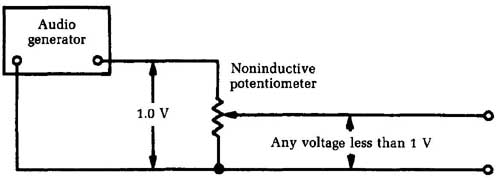
FIG. 3 It might be more convenient to use a 1K potentiometer in the volt
age divider network. Lamp to match rated power output of amp
Measuring amplifier output power with a multimeter
The lamp test for audio amplifier output power described previously is sufficient for some purposes, but it’s obviously a very crude and inexact test. If you need a more exact indication of an audio amplifier’s output power, you can use an audio wattmeter, but such a device is not a standard element on most electronics workbenches. If you do a lot of work with audio amplifiers, you probably will want to buy a good audio wattmeter, but most technicians will only have an occasional need for such an instrument. Rather than clutter up your work area a lot of equipment that will spend most of its time just gathering dust, you might want to use your general test equipment.
For this test, you will use a signal generator or audio frequency oscillator and a multimeter. It doesn’t much matter if the multimeter is of the analog or digital type in this application.
The signal generator can put out almost any simple ac wave form. A sine wave would probably be the best choice, but this is hardly critical. A frequency of 1000 Hz (1 kHz) would be the ideal for performing this test procedure, but again this isn’t terribly critical. You don’t have to worry about setting the signal frequency precisely.
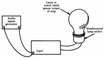
FIG. 4 The test hook-up for a simple check of audio power output.
The signal generator you use should have a low output impedance, of no more than 600 ohm or so. To prevent overloading the inputs of the amplifier being tested, it’s highly desirable to use a signal generator with an attenuator (output signal level) control. Set the signal level to suit the specific amplifier’s input requirements. For instance, most standard stereo amplifiers call for a 1 V input at the auxiliary input jack(s) to drive the amplifier to its full power output, which is exactly what we want in this test.
The basic test setup is illustrated in FIG. 5. Set up the multi- meter to read ac volts. Notice that a load resistor is used in place of the loudspeaker at the output of the amplifier to avoid the complexities and possible mis-readings that might result from the ac impedance of the speaker’s voice coil. Things will be much simpler if only straight dc resistance is involved.
The resistor’s value should be equal to the nominal impedance of the speaker. For most modern stereo amplifiers, this amount will probably be 8 12. Other common values you might encounter are 4 12 and 16 12. Some PA amplifiers might call for speakers with higher impedances. In most cases, the correct out put impedance value will be indicated on the back of the amplifier near the output jacks or screw terminals.
A high-power resistor must be used in this application. The resistor’s power rating should be equal to at least the expected power output of the amplifier being tested. We strongly advise overrating this resistor’s power handling capability by at least 10 to 25 percent. For example, if the amplifier you are testing is rated for 10 W, use a resistor that can withstand at least 11 to 13 W.
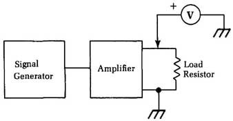
FIG. 5 The basic test setup for measuring amplifier output power with a multimeter.
Load Resistor, etc.
If the amplifier being tested has any tone controls or filters, set them all for flat response while performing this test procedure.
You can use the ac voltage measured across the load resistor to determine the output power with this standard formula:
P=E^2/R
…where P is the power in watts, E is the measured voltage in watts, and H is the value of the load resistor.
As an example, assume that the load resistor has a value of 8-ohm. Also assume that the amplifier you are testing is rated for 15 W.
It’s a good idea to first perform this test at less than full volume. Set the amplifier’s volume control at about one-half to two- thirds of full scale. Let’s say we measure an ac voltage of 7.5 V. What is the wattage of the amplifier’s output signal? Just plug the known values into the equation:
=(75^2)/8
=7.5 x 7.5/8
=56.25/8
= 7.03125 W
You can round this figure off to 7W. This seems reasonable for the 15 W amplifier of the example, so you can proceed. If, however, you got a strangely low power level (say, only 2 or 3 W), or an oddly high wattage (say, 25 W), there is apparently something wrong. Trouble-shoot and correct the problem before proceeding. Attempting to run a defective amplifier at full volume might cause extensive damage, which is why we performed the test at a lower volume first.
Now, crank up the amplifier’s volume control all the way to its maximum setting and repeat the measurement. This time, let’s say you got a reading of 11.25 V. The maximum power output is:
P=11.25^2/8
=11.25 X 11.25/8
=126.5625/8
= 15.820312 W
This is close enough to your expected rated value of 15W. It’s a bit high, but not excessively so. The difference might be due to several causes, including accumulated measurement errors, component tolerances, or possibly the manufacturer simply rounded off the actual power rating to give a little “fudge room.”
It will be rare to get a too-high power level. If the amplifier is malfunctioning, it will probably give a much lower than normal wattage value. A defective transistor in the amplifier’s circuitry is a likely cause.
This test is useful, but it’s still fairly crude. It doesn’t give you much information. You know the absolute signal amplitude, but you don’t know how badly the signal is being distorted by the amplifier or how smooth the frequency response is. The output power might be significantly higher or lower at other signal frequencies. Other tests will be needed to identify such problems.
An oscilloscope can be used to help spot distortion problems. Refer back to section 5. A test procedure for an audio amplifier’s frequency response is outlined in the next section.
Testing an audio amplifier’s frequency response
No practical amplifier circuit is perfect. All practical electronic circuits are frequency sensitive, at least to some extent. Not all frequencies will be amplified by the exact same amount. Some will receive a little extra boost, while others will be attenuated. A high-fidelity amplifier is designed to exhibit as flat a frequency response as possible. The differences in amplification for all frequencies in the audible spectrum should be nonexistent, or at least reduced to a negligible level. For many modern amplifier circuits, there are no measurable fluctuations in the audible frequency response. There probably are some, but if they are too small to measure, they are almost certainly inaudible.
The ideal frequency response specification for a high-fidelity audio amplifier is 0 dB. This specification indicates a perfectly flat response within the stated frequency range. (If no frequency range is specified, the standard audible range of about 20 Hz to 20 kHz (20,000 Hz) can be assumed.) A practical audio amplifier might have a frequency response specification like 25 W±1 dB. This means that no frequency signal within the audible range will be less than 1 dB below 25 W or above 1 dB above 25 W when the amplifier is operated at full volume.
The decibel (dB) is a comparative value. It has no absolute meaning, like the volt. It’s a definite, unambiguous unit. But to say a certain signal is I dB is meaningless unless you say what it’s being compared to. It’s 1 dB above (or possibly below) some reference point. In audio work, you sometimes will encounter dB values with no stated reference. Audio technicians have a standard, agreed upon reference value of 6 mW (0.006 watts), which is equal to 1.9 V across a 600 ohm resistance. For our purposes, if you see that an amplifier has a power level of 5 dB, you know that its power rating is 5 dB greater than 6 mW.
It’s important to realize that the dB scale is logarithmic, rather than linear. A value of 2 dB is not twice as much as 1 dB ion the same way that 2 V is twice as much as 1 V. For decibels, a doubling of power is a difference of 6 dB.
Most analog multimeters have a decibel scale, usually the bottommost scale on the dial face. Some deluxe DMMs also might have a dB scale, but they are the exceptions, rather than the rule, so you will probably want to use an analog multimeter for this type of test.
The centerpoint on the dB scale is marked 0. Readings to the right of this point are positive, and readings to the left are negative. A negative dB value indicates that the measured quantity is less than the reference value; a positive dB value indicates that the measured signal is higher than the reference value.
The dB scale on a multimeter is calibrated assuming the 600 ohm audio standard. (Some sources give a standard impedance of 500 ohm.) In practical terms, the difference is negligible except for high-precision tests. If you need that much precision, you should be using specialized laboratory-grade equipment anyway, not a simple VOM.
The values printed on the dB scale are valid only for one specific ac range, usually (though not always) the lowest ac volts range the meter offers. For higher ranges, you will need to add a specific adjustment factor. The number of dB to be added to the reading for each range is usually printed on the meter’s faceplate in the lower right corner. For example, a particular multimeter might have the dB scale calibrated for the 5 Vac range. For the 10 Vac range, you must add 6 dB to each reading, and on the 50 Vac range, you must add 20 dB. If you are operating the meter on the 10 Vac range and get a reading of 0 dB, the measured signal has a value of 6 dB 110 db (reading) + 6 db + 6 dB (adjustment factor)].
To actually make the measurements, use the same setup from the output power test described earlier. A signal generator drives the amplifier (or other audio circuit or device), and the reading is taken off the load resistance. This test setup was shown in Fig. 5.
For most audio amplifiers you will have a severe impedance mismatch. The amplifier’s output is designed to drive an 8 ohm (typical) load, but the multimeter is calibrated assuming a load resistance of 600 ohm. You won’t get very accurate readings using this method. Shortly we will give an alternate method. You can get some crude relative readings, which might be sufficient for some quick-and-dirty testing, but the actual dB values will probably be way off.
On the other hand, the output impedance of some audio equipment will have the correct impedance. Such equipment includes tape decks, preamplifiers, mixers, microphones, and synthesizers. You can use this test procedure directly for such de vices.
Set all tone controls, equalizers, and so forth to their flat position before making any test measurements. Set the volume control in one position and leave it alone. Typically, the halfway point will be a good choice for basic frequency response tests.
Measure the output signal level using the dB scale with the signal generator. set for the lowest frequency of interest. Note the dB reading. Now, raise the signal frequency of the signal genera tor. Check the input signal voltage to make sure it has not changed with the change in signal frequency. If it has, adjust the signal generator’s attenuator so the circuit under test sees the same input signal level. Now, measure the output signal level on the dB scale, as before. Make a note of the value. Repeat this process for a number of discrete frequencies throughout the range of interest.
Ideally, you should get the same dB value for each test frequency across the unit’s desired range. Any fluctuations in the values indicate irregularities in the device’s frequency response. It’s often helpful to graph the results for a visual image of the circuit’s overall frequency response.
A good set of test frequencies for high-fidelity audio equipment is 20Hz, 50Hz, 100 Hz, 400 Hz, 1,000 Hz, 1,500 Hz, 5,000 Hz, 7,500 Hz, 10,000 Hz, 15,000 Hz, and 20,000 Hz. These values will give you a good practical impression of the overall frequency response of the equipment you are testing. Remember, the human ear hears changes in frequency logarithmically, so the difference between 100 Hz and 200 Hz sounds the same as the difference between 500 Hz and 1,000 Hz.
If you have to check the frequency response of an amplifier or some other audio circuit but the output is designed for a load resistance other than the nominal 600 assumed by the dB scale, you can still perform a variation on this test, although it will be a little more work, and you will have to do a bit more math. In this case, you don’t use the multimeter’s dB scale. Use the regular ac volts scale of the appropriate range. Measure the ac voltage across the load resistor for each test frequency and note the measured value. Also calculate the power value for each test frequency, using the standard power formula:
P=E^2/R
…where P is the power in watts, E is the voltage in volts, and R is the resistance in ohms.
It’s usually helpful to first perform the test at a medium frequency, such as 1,000Hz, and adjust the volume control for a convenient value, such as 4.0 V. Assuming an 8 load resistance, this corresponds to a power level of:
P=4^2/8
=4X4/8
=16/8
=2 Watt
Table 1 shows a fairly typical set of results. Graph the out put power and frequency, as illustrated in Fig. 6. The flatter this line is, the better the frequency response of the amplifier. The amplifier used in this example is just fair, at best. Most modern audio equipment will have a much better frequency response than this. This rather poor-quality amplifier was chosen for this example because it most clearly illustrates what we are talking about. There will usually be the greatest attenuation at the lowest and highest frequencies. There might be one or two dips or peaks in the mid-range, as in our example.
Remember, the tone controls on any piece of audio equipment are designed specifically to change the frequency response from a nominal flat line. For example, a bass tone control is used to selectively boost or attenuate the lowest frequency elements in the signal. To get accurate results, all such tone controls must be set to a flat position before performing the frequency response test.
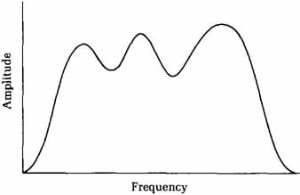
FIG. 6 A graph is the most convenient way to indicate the frequency response
of an amplifier, or other circuit.
A quick test for the RF power output of a transmitter
An incandescent lamp of the proper wattage rating makes a good quick-and-dirty test for RF power output in high-power transmitters (anything from about 10 W up). Get a weatherproof lamp socket, a rubber-covered type with pigtail leads, and connect it to about 18 inches of coax with a PL-259 plug on the end. If you find a transmitter where there is doubt about the actual power output, screw this plug onto the antenna socket, put a lamp of the appropriate wattage in it, and key the transmitter. See FIG. 7.
Table 1 Some typical results of the frequency response tests described in the text.
Test frequency | Measured output voltage | Output power
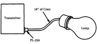
FIG. 7 The test hook-up for a simple check of RF power from a transmitter.
If there is any RF power output, the lamp will light up. Since there is nothing but RF in the antenna circuit, a glowing lamp means that the transmitter has RF output and the trouble must be in the modulation, frequency, or something of that sort.
This light-bulb test is very useful for getting a quick start on those troubles where the problem could be in either the transmitter’s final stage or the transmitting antenna. If the lamp lights up to a good white glow but there’s very little output from the antenna, check the antenna and transmission line; that transmitter’s okay. Although the mismatch between the transmitter and the lamp is theoretically something awful, you’ll be surprised how little you have to change the tuning adjustments between the lamp and the regular antenna.
For CB transmitters, use a No. 47 pilot light. Even lower power? Try a No. 49.
Measuring base bias voltage in high-resistance circuits
In a few audio-amplifier applications, you’ll find very high value resistors used in the base voltage-divider circuits. One well known make , for example, uses a 12 M resistor as part of the net work. Even the 11 M resistance of a VTVM will upset this circuit if it’s shunted across. Since it takes only a fraction of a volt to cause a big change in transistor currents, measuring the base bias directly is not a good procedure.
Set makers recommend measuring collector and emitter voltages as given in the service data. If these values are correct, then the base bias must be right. In other words, avoid getting into the very high resistance circuit to measure base voltage. Instead, measure the voltages that this voltage affects.
If you want to check out the base-bias circuit, remove the transistor and measure the large resistors for proper value, especially if the collector and emitter voltages are off-value.
Finding breaks in multi-conductor cables
Multi-conductor cables are very handy in many applications. For example, a computer is connected to a printer via a multi- conductor cable, and a set of intercoms are interconnected with multi-conductor cables. A multi-conductor cable, of course, is nothing but a bundle of individually insulated conductors grouped together into a single cable and held together by an outer jacket of some sort, usually a hollow tube of the insulating material.
When interconnected devices aren’t working together properly, the problem is often likely to be a break in a multi-conductor cable. How can a technician track down such a fault and identify which individual conductor in the multi-conductor cable is defective? A simple circuit for accomplishing this task is shown in FIG. 8. This circuit is so simple, there is no need for a separate parts list. Resistor R1 is simply a current-limiting resistor to protect the LEDs. Any value between 330 and 470 would be suitable.
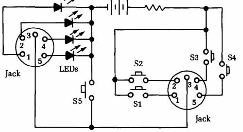
FIG. 8 This circuit can be used to locate a break in a multiconductor cable.
A standard 9 V transistor radio battery is used as the power source in this circuit. You could use a 6 V battery if you prefer, but 9 V batteries are small, inexpensive, and convenient. They are also very easy to find.
The two jacks are selected to match the plugs on either end of the cable to be tested. A five-conductor cable is assumed in this drawing, but you can easily increase or decrease that number to suit the specific multi-conductor cable you are working with. Except for the ground pin (or pins), each individual pin (conductor) gets its own LED on the left-hand side and its own push-button switch on the right-hand switch.
In operation, with the multi-conductor cable plugged into the two jacks, closing one of the switches should cause the appropriate LED to light up. If not, there is probably a break in that cable. If more than one LED lights up, there might be a short between those conductors.
The test for the ground connection is slightly different. Close switch S5. Nothing should happen. If any of the LEDs light up, there is a short in the cable, and it probably should be replaced.
Finding a break in a coaxial cable with a capacitance tester
You can use almost any piece of test equipment for many applications. For instance, you can use a capacitance tester to locate a break in the inner wire of a coaxial cable, such as a microphone cable, coaxial lead-in, etc. There are two ways to do so. If you know the type of cable, you can find its capacitance per foot from a catalog or the Radio Amateur’s Handbook. Then hang the capacitance tester onto one end. Divide the reading by the capacitance per foot, and you have the distance of the break, in feet, from the end you measured at. The second method, if you know the length of the cable but can’t find its capacitance per foot, is to measure first at one end, then at the other, and write both readings down. Call one READING 1; the other READING 2. Divide READING 1 by the sum of both readings, and multiply that number (which will be less than one) by the total length of the cable. The result is the distance of the break from the end at which you took READING 1. Of course you r also use READING 2 in the same manner. This test is illustrated in FIG. 9.
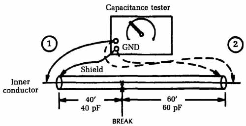
FIG. 9 A capacitance tester can be used to find a break in a length of coaxial
cable. Capacitance tester; Inner conductor.
Most breaks in microphone cables happen near one end or the other because of the bending and flexing near the plugs. To find out which end is broken and save tearing the plugs apart needlessly, take a capacitance reading from each end. One end will show a large capacitance, the other practically none; the latter is the broken end.
You also can use a capacitance test to find a broken wire in side the insulation of a two-conductor cable. Use the good wire as the “shield” and measure the capacitance of the broken wire to it. Otherwise, the method is the same.
Measuring true rms voltages
Measuring dc voltages is generally straightforward. The only possible source of confusion is the reference point for the voltage measurement. However, the circuit’s ground potential normally is used as the zero reference point and the few exceptions are usually clearly indicated.
Things get more complicated when you start dealing with ac voltages. An ac voltage, by definition, is constantly changing its value. There are several different ways to measure ac voltages, which are useful in certain circumstances. For instance, in some cases you are concerned with absolute maximum values. Here, you want to know the peak voltage reached during the ac wave form’s cycle. For convenience, assume all waveforms are centered around 0 Vdc.
An AC voltage might be in the form of a sine wave with a peak voltage of 10 V. (It also would have a peak negative voltage of - 10 V.) To say you have 10 Vac would be misleading because the peak value is reached for only a tiny fraction of each cycle. For most of the cycle, the instantaneous voltage is considerably less than the peak value.
Because the voltage varies between +10 V and -10 V, it covers a 20 V range. In some instances, it’s useful to measure the signal as 20 V peak to peak. Once again, though, saying there’s 20 Vac would be misleading.
The logical approach would be to take an average of the instantaneous voltages throughout a cycle. You can’t use the entire cycle, however, because for a symmetrical waveform the positive half-cycle and the negative half-cycle will always cancel each other out, leaving an average value of 0 V.
For average ac voltages, only half of each cycle is considered. It has been mathematically proven that for a sine wave, the aver age voltage is always equal to 0.636 times the peak value. In our example of a sine wave with a peak voltage of 10 V, the average value would be 6.36 volts.
This is not unreasonable, and average values will allow you to meaningfully compare various ac voltages. Unfortunately, the formulas of Ohm’s law don’t hold true for average voltages. This is a major loss to the electronics technician because so much of circuit design and analysis is based on the relationships described by Ohm’s law.
What you need in order to retain Ohm’s law for ac voltages is a way to express ac voltage in terms that can be compared directly to an equivalent dc voltage. To find such an equivalent value, take the root mean square (rms) of the waveform. For a sine wave, the rms value is always equal to 0.707 times the peak value. In the example, the 10 V peak ac sine wave would be measured as 7.07 V rms. This signal would heat up a given resistor exactly the same amount as 7.07 Vdc through the same resistor. The voltage/cur rent/resistance relationships defined by Ohm’s law work out the same for rms values as for dc values. As a rule, ac voltage and cur rent relationships usually are measured as rms values.
We have gone into some depth here because even experienced technicians occasionally get confused. For your convenience, the following is a handy comparison of the various ac measurements.
Rms = 0.707 x Peak
= 1.11 x Average
Average= 0.9 X rms
Average=6.36 X Peak
Peak = 1.41 X rms
Peak = 1.57 X Average
Peak-to-peak =2 x Peak
Firs have to convert an ac value form one from to another. Remember that these equations hold true only for sine waves. They cannot be used for other waveforms.
Most ac voltmeters are calibrated to measure ac voltages for sine waves. These meters won’t be accurate for ac signals with any other waveshape. You are usually only concerned with making simple comparisons, so an ac voltmeter should suffice even for non-sine-wave signals. However, if you need a true rms value for a non-sine-wave signal, a standard ac voltmeter is virtually use less. Moreover, standard ac voltmeters are frequency dependent. They are tuned for accurate measurement at the standard line frequency (60 Hz).
These meters do the job fine for at least 75 percent of all ser vice jobs. There are, however, occasions when they fall short. Until fairly recently, the technician didn’t have much choice in the matter. If a standard ac voltmeter couldn’t do the job, then you settled for compromised measurements, estimating, and making educated guesses.
Today, there are computer-driven meters that can perform the necessary mathematical calculations. Even better, the last few years have seen the development of specialized ICs that per form rms-to-dc conversion. An ac signal with almost any wave- shape is fed into the input, and a proportionate dc voltage appears at the output. This dc voltage is the same as the true rms value of the input signal. These chips are starting to be used in multi- meters, especially those of the digital variety. Two of the first rms-to-dc converter chips were the AD637, shown in FIG. 10, and the AD536AJD, which is illustrated in FIG. 11.
Testing transistors
The vast majority of transistors are of the standard bipolar variety. Bipolar means that the semiconductor contains two pn junctions. The bipolar transistor is essentially a semiconductor “sandwich,” as illustrated in FIG. 12.
Functionally, the bipolar transistor can be considered a pair of back-to-back diodes interconnected, as shown in FIG. 13. This is just an illustrative simplification. Normally, you cannot replace a transistor with two discrete diodes.
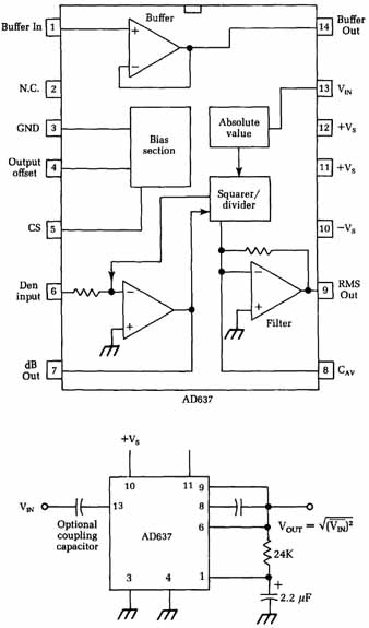
FIG. 10 The AD637 is a rms-to-dc converter IC.
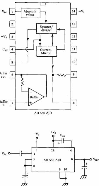
FIG. 11 Another rms-to-dc converter IC is the AD536AJD.
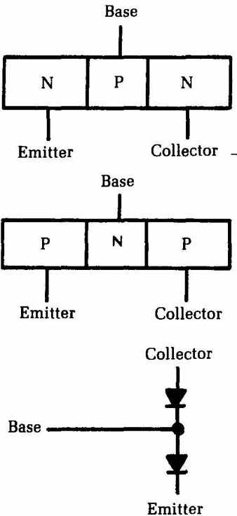
FIG. 12 [Emitter, Base, Collector,] A bipolar transistor is essentially a
semiconductor “sandwich.”
FIG. 13 Functionally, the bipolar transistor is somewhat like a pair of back-to-back diodes. Base, Emitter
You can test a diode easily with an ohmmeter. Simply mea sure the resistance from one lead to the other, then reverse the leads and measure the resistance again. This process is illustrated in FIG. 14. You should measure a very high resistance in one direction and a low to moderate resistance in the opposite direction. If the resistance is high no matter which way you position the meter leads, the diode is open. If you measure a very low resistance in both directions, the diode is shorted.
Test a bipolar transistor in a similar way. Measuring between any two leads should give approximately the same results as with a single diode. In all, you need to make six measurements:
- • Emitter to base
- • Base to emitter
- • Emitter to collector
- • Collector to emitter
- • Collector to base
- • Base to collector
An incorrect reading on any of these measurements indicates that the transistor is bad and should be replaced.
In almost all cases, you should make these tests with the transistor out of the circuit. And other circuit resistances in parallel with the pn junction being measured will throw the reading off, especially if the parallel resistance has a low value.
The ohmmeter test works, but it’s a little tedious to swap the test leads around six times. A dedicated transistor tester is a lot more convenient. Some very fancy transistor testers are available that measure transistor parameters such as alpha and beta.
These devices can be useful in certain cases, but for most re pair work, you only need a simple “go/no-go” type of test. Many simple circuits have been designed for this purpose. Perhaps one of the simplest is the one shown in FIG. 15. You could easily build such a circuit in less than a half hour. The odds are good that you already have all the necessary components handy. The circuit is powered from an ordinary 9 V transistor radio battery.
Insert the transistor to be tested in the socket. Alternatively, you can replace the socket with test leads that have alligator clips on the ends. Attach the clips to the appropriate leads of the transistor. If the transistor to be tested is npn, set the dpdt switch to position A; set this switch to position B for pnp transistors.
Close the momentary-contact push button to test the transistor. If the transistor is good, the appropriate LED should light. If the LED does not light, assume the transistor is bad and replace it.
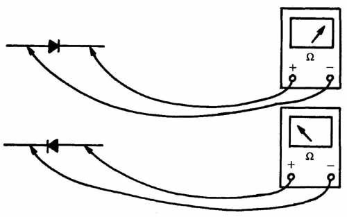
FIG. 14 A diode or other single pn junction can be tested with an ohm meter.
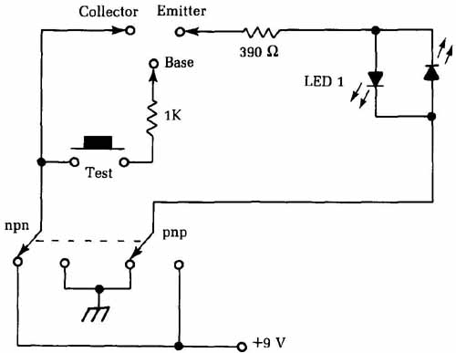
FIG. 15 A circuit for performing simple “go/no-go” tests on bipolar transistors.
Collector Emitter Base
You also can use this handy little circuit to identify a transistor’s type. Simply test the transistor with the dpdt switch in both positions. In one position, an LED should light, while in the other position both LEDs should remain dark. You can identify the type of transistor by which LED lights. If neither LED lights at either position of the dpdt switch, the transistor is probably bad.
Both of these test procedures are for bipolar transistors only. If you try them on other transistor types, you won’t get correct readings. Also, these tests work for out-of-circuit transistors, but you won’t always get meaningful results if you attempt the test on a transistor wired into a circuit. This is a fairly serious limitation for servicing work.
Remember that all semiconductors are heat sensitive. If you’re not careful, you can destroy a transistor when desoldering or resoldering. Always use a heatsink when soldering or desoldering around semiconductor components. The spring-loaded clip-on types, as shown in FIG. 16, are usually the most convenient to use. If you don’t have one handy, fashion a make-shift heatsink out of a large paper clip. The larger the heatsink is, the more heat it will conduct away from the transistor. When in doubt, use a larger heatsink.
Obviously, it’s impractical to desolder every transistor in a piece of equipment for out-of-circuit testing. Such a procedure should be limited to components where there is good reason to assume they’re bad.
It usually isn’t too difficult to isolate potentially troublesome transistors by making current and voltage tests. Standard values are usually printed in the schematic, Don’t worry too much about minor errors. Look for voltage and current values that are significantly off. If a signal being fed into a transistor is correct and the voltage or current coming out isn’t, then it’s reasonable to suspect that transistor.
Don’t be too quick to jump to conclusions, however. Often, a perfectly good transistor can look bad because of a problem in one or more of its associated components (resistors, capacitors, etc.). Even if you remove the transistor and find it tests bad, check the associated components anyway. Almost every electronics technician has had the frustrating experience of replacing a bad transistor only to have the new component soon blow out, too. Something else is wrong, causing the transistor to go bad.
Actually, such multiple problems are more common than you might suspect. Semiconductors are pretty reliable. Unlike tubes, transistors seldom go bad by themselves, although it has been known to happen occasionally. Usually something external has caused the transistor to go bad. In some cases, the transistor has been damaged by a transient that somehow managed to get into the circuit. In such an instance, there might be nothing else wrong with the circuit. When the transistor is replaced, the unit will work just fine. More frequently, however, the transistor’s problem will have been caused by a resistor that has changed value, an open or leaky capacitor, or something similar.
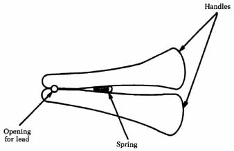
FIG. 16 A bipolar transistor is essentially a semiconductor “sandwich.”
Handles; Opening for lead; Spring
Problems caused by other components might not always be obvious. Often it takes them a while to damage the new transistor. Run the equipment at least a half hour after making the repair to reduce the number of call-backs and irate customers you might have to face.
There is one final point about transistors you should be aware of. Unlike tubes, transistors are usually either definitely good or definitely bad. They are rarely weak. Once again, though, there are exceptions, so never be too hasty to jump to conclusions. On those rare occasions when you suspect a leaky transistor, you need a high-quality transistor tester to check it. A VOM/VTVM or the “go/no-go” tester like the one shown back in FIG. 15 won’t be enough. A silicon transistor can have leakage as small as 10 to 15/2A. This small amount of current error is very difficult to measure by standard methods but can be sufficient to throw off proper circuit operation and cause all sorts of strange symptoms.
You should suspect a leaky transistor when everything in the circuit seems okay, but the circuit simply doesn’t work the way it ought to. If all passive components are good, then an active device (such as a transistor) must logically be the culprit.
To perform a leakage test with a transistor, you almost always need to remove the component from the circuit. If you don’t have a suitable transistor tester for the leakage test, but do have a du plicate of the questionable transistor, try substituting the duplicate in the circuit. If the circuit then works properly, it’s safe to assume that the original transistor was leaky and should be discarded. On the other hand, if the symptoms persist, the odds are very strong that the problem lies elsewhere. It’s extremely un likely you’ll encounter two leaky transistors (the original and the duplicate) in a row.
Testing Zener diodes
There are many specialized semiconductor components. Often they require specialized testing procedures. In this section, we will look at methods for testing several popular semiconductor components that cannot be tested usefully in the same way as bi polar transistors and basic junction diodes.
The Zener diode is a special type of diode. FIG. 17 shows a graph of the operation of an ordinary junction diode. If the applied voltage is near 0, the diode won’t conduct. It will act like an open circuit, and no current will flow through it. When the applied voltage is increased past a specific positive voltage, the diode will start to conduct and will act pretty much like a short circuit. This forward-bias voltage is typically very small—about 0.3 V for germanium diodes and about 0.7 V for silicone diodes.
On the other hand, if you start at an applied voltage of 0 and increase the voltage in a negative direction, nothing will happen. The diode will be reverse-biased, and it will conduct little or no current. It continues to act like an open circuit. When some specific negative voltage is exceeded, however, the diode’s junction will break down, and it will start to conduct very heavily, which will almost always permanently damage or destroy the diode. The reverse breakdown voltage varies with the construction of the specific diode in question, but it’s always a relatively high value.
FIG. 18 is a graph of the operation of a Zener diode. In the positive direction, the Zener diode works pretty much like an ordinary junction diode. Below about 0.6 V, the diode won’t conduct, but when the applied voltage exceeds 0.6 V, the Zener diode’s resistance will drop considerably, and a fairly large cur rent will flow. So far, we have nothing special here.
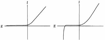
(left)
FIG. 17 A graph of the operation of an ordinary semiconductor diode. (right)
FIG. 18 The Zener diode is a special type of semiconductor diode.
A Zener diode operates uniquely when it’s reverse-biased. A small negative voltage won’t have much effect. The high resistance of the reverse-biased diode means that virtually no current will flow through the device. When a specific key voltage (Vs) is exceeded, however, the junction resistance drops to a very low level, permitting the Zener diode to conduct fairly large currents, but the junction does not permanently break down. The Zener diode is not damaged by this negative conduction.
The most important feature is that this Zener voltage (VJ does not change as the applied voltage is increased. For example, if a Zener diode is rated for 6.8 V, there will never be a reverse- biased voltage drop greater than 6.8 V across this component. Be cause of this unusual response, the Zener diode is used widely in voltage-regulator and reference-voltage applications.
Zener diodes are available with V voltages ranging from about 2 to 200 V, and with power-handling capabilities of 0.25 up to 50W. Even a Zener diode can be damaged if the reverse voltage is too large, but this usually takes a very large negative voltage. To prevent the Zener diode from self-destructing by drawing excessive current, you should use it with a current-limiting resistor.
To distinguish it from an ordinary junction diode, a special schematic symbol is used for the Zener diode. This symbol is shown in FIG. 19.
FIG. 19 The standard schematic symbol for a Zener diode.
Because of their small physical size, Zener diodes are usually unmarked. Occasionally, the electronics technician will need to determine the Zener voltage of an unmarked Zener diode. That is the purpose of this test procedure. A defective Zener diode will either be open or shorted, which can be determined with an ohm meter, as with ordinary junction diodes.
The basic Zener diode test setup is illustrated in FIG. 20. The dc voltage source (B1) should be somewhat larger than the expected V voltage. This source voltage can be attenuated manually via the voltage divider network made up of R1 and R2. It would be even better to use a variable dc power supply in place of B1, R1, and R2. Resistor R3’s value should be selected to limit the current to no more than about 10 mA to 20 mA.
Notice that a voltmeter and a milliammeter are simultaneously used in this test. You can use two multimeters or you can use a multimeter and either a dedicated voltmeter or milli ammeter. You must make the two measurements simultaneously.
Start out with a voltage of 0 (zero), or as close to 0 (zero) as possible. (Potentiometer R2 is adjusted for its maximum possible resistance.) You should read little or no voltage or current on the meters. Now, slowly increase the applied voltage (reduce the resistance of potentiometer R2). The reading on the voltmeter should increase with the increasing applied voltage, but the milliammeter should continue to give a 0 or near 0 current reading. Continue increasing the applied voltage. As this voltage nears the V value, the cur rent flow will start to increase. Once the V value has been passed, the voltmeter should read V and the milliammeter should indicate a drastic increase in the current flow. Increasing the applied voltage further should not change the reading of the voltmeter. The voltage the meter “got stuck on” is the V value for the Zener diode you are testing.
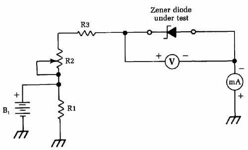
FIG. 20 The basic test setup for checking Zener diodes. Zener diode under
test.
If you don’t get the results described, you did something wrong in the test procedure, or the Zener diode being tested is defective. Make sure the diode you are testing really is a Zener diode. Other types of diodes could give very strange results, if they are not damaged by the test procedure.
Testing FETs
A field-effect transistor (FET) is quite different from an ordinary bipolar transistor. Its operating characteristics are much closer to those of old-fashioned vacuum tubes, offering the advantages of tubes without the excessive bulk, fragility, and heat that are inevitable with vacuum tubes.
The basic schematic symbol for a FET is shown in FIG. 2 1. Notice that, although it has three leads, they are not called base, emitter, and collector as in the bipolar transistor. Instead, the three leads of a FET are referred to as gate, source, and drain. FIG. 22 is a very simplified drawing of the basic internal structure of a FET.
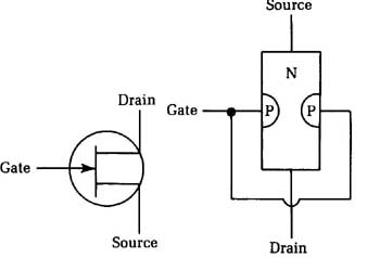
FIG. 21 A FET is quite different from a bipolar transistor. (right) FIG. 22 A
simplified drawing of the internal structure of a FET.
The signal applied to the gate terminal of a FET controls the amount of electric current that can flow from the source to the drain. A negative voltage applied to the gate lead reverse-biases the pn junction, producing an electrostatic field (electrically charged region) within the n-type material of the component’s body. This electrostatic field opposes the flow of electrons through the n-type section, acting somewhat like a partially closed mechanical valve in a plumbing system. The higher the negative voltage applied to the gate, the less current that is al lowed to pass through the device from source to drain. Increasing the negative voltage “closes the valve” further.
This procedure is directly analogous to the action of a vacuum tube. The gate of the FET corresponds to the grid of the tube, controlling the amount of current flow. The source is the equivalent to the cathode (it acts as the source of the electron stream), and the drain serves essentially the same function as the plate (it drains off the electrons from the device). The path from the source to the drain is sometimes called the channel.
FETs have a very high input impedance, so they draw very little current. This is because of Ohm’s law, which states:
I=E/Z
…where I is the current in amperes, E is the voltage in volts, and Z is the impedance (ac resistance) in ohms. Increasing the value of Z will decrease the value of I.
The high input impedance of a FET means that it can be used in highly sensitive measuring and monitoring applications and in circuits where it’s important to avoid loading down — drawing heavy currents from—previous circuit stages. This is another way in which FETs functionally resemble vacuum tubes.
The vast majority of FETs are of the n-channel type, as shown here, but FETs also can be made with a p-type channel and an n type gate. These devices will work in the same way, except all polarities will be reversed. In this case, you must think of a positive voltage on the gate opposing the flow of holes through the channel. The schematic symbol for a p-type FET is the same as for an n-type unit, except the direction of the arrow on the gate lead is reversed.
The gain of a FET is usually identified as Y_fs, although this is not fully standardized, and other terms will be frequently en countered. The formula for FET gain is:
Y_fs = delta I_d / delta V_gs
where I_d is the drain current, and V,, is the gate voltage for the FET in a common-source circuit. The small triangles (A) represent the Greek letter delta and are used to indicate changing, rather than static, values.
A circuit for testing n-type FETs is shown in FIG. 2 3. To use this circuit for p-type FETs, you must reverse all polarities throughout the circuit. Notice that both a voltmeter and a milliammeter are used at once in this circuit. You can use two multimeters, or you can use a multimeter and either a dedicated voltmeter or milliammeter. You must make the two measurements simultaneously.
Set the dc voltage source for some specific voltage. The exact value is not too crucial, as long as it’s within the FET’s usable range. If you use a 9 V battery for Bi, you shouldn’t have to worry about this limitation. The voltmeter V shows the value, while the milliammeter indicates the ‘d value. You can find the static gain simply by dividing these two values:
Y_fs = I_d / V_gs
Unfortunately, this won’t give you a very meaningful indication of how the FET will actually work in a practical circuit. So make a note of the measured ‘d and V values. Then change the applied voltage and take the measurements again. Determine the difference between the two ‘d values and the two V values, and use these change values to calculate the FET’s dynamic gain. This test circuit is not intended for in-circuit tests of a FET.
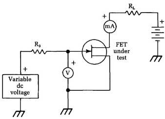
FIG. 23 This circuit can be used to test n-type FETs
Testing SCRs
A silicon-controlled rectifier (SCR) is essentially an electrically controllable diode, or rectifier. In addition to the anode and cathode, there is a third lead, called a gate. The standard schematic symbols used to represent this semiconductor component are shown in FIG. 24. The circle around the symbol is optional and does not change the meaning of the symbol in any way.
FIG. 24 The SCR is like an electrically switchable diode.
With no signal applied to the gate, no current can flow through the SCR from cathode to anode. A brief pulse, or trigger, signal of sufficient voltage applied to the gate terminal will turn the device on. The SCR will then conduct from cathode to anode, pretty much like an ordinary two-lead rectifier, even if the gate signal is totally removed. The only way to turn the SCR back off is to drop the voltage applied from cathode to anode below a specific threshold level, which is determined by the design of the SCR.
A rough equivalent circuit for a SCR made from a pair of bi polar transistors is shown in FIG. 25. This is a conceptual illustration only, and not a practical circuit. You cannot substitute a couple of bipolar transistors for an SCR in a working circuit.
Ordinary diodes are two-layer semiconductor devices. That is, there is a slab of p-type semiconductor and a slab of n-type semiconductor. A bipolar transistor is a three-layer device. In an npn transistor, two relatively thick slabs of n-type semiconductor are separated by a relatively thin layer of p-type semiconductor. In a pnp transistor, this arrangement is reversed—two relatively thick slabs of p-type semiconductor are separated by a relatively thin layer of n-type semiconductor.
An SCR is somewhat more complex in its internal construction. It’s a four-layer semiconductor device, with two slabs of n-type material and two slabs of p-type material, interleaved as illustrated in FIG. 26. Because it’s a four-layer semiconductor device, the SCR is one of a class of components known collectively as thyristors. Because the SCR’s internal construction is so different from standard diodes or bipolar transistors, it’s clear that you can’t use the same test procedures for this type of component.
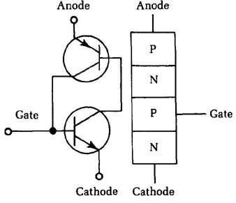
FIG. 25 A rough (not functional) equivalent circuit for a SCR is comprised
of a pair of bipolar transistors. (right) FIG. 26 A SCR is a four-layer semiconductor
component, or a thyristor.
It’s fairly easy to test the gate turn-on voltage of an SCR. Just apply a variable dc voltage supply to the gate lead, as shown in FIG. 27. The load circuit illustrated is a simple LED indicator. When the SCR is turned on and conducting, the LED will light up. When the SCR is off, the LED will be off.
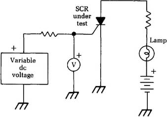
FIG. 27 The circuit for testing the gate turn-on voltage for a SCR. Lamp
Start the gate voltage at 0 and gradually increase it, while watching the LED. As soon as the LED lights up, stop increasing the voltage and look at the reading on the voltmeter. The volt meter will directly indicate the voltage required to turn on this particular SCR.
Notice that once the LED starts glowing, increasing or de creasing the gate voltage, or even disconnecting the voltage source altogether, has no effect. To turn off the LED and reset the SCR, briefly open the NORMALLY CLOSED push-button switch in the LED circuit. This action will cut off the current flow from cathode to anode and turn off the SCR.
If the LED is always lit, or if it never lights, the odds are good that the SCR being tested is defective and should be replaced. Of course, before you draw any conclusions, you should double- check the wiring of your test circuit to make sure a mistake there isn’t the problem.
In some applications, you will need to know the gate current I_G of a SCR. Because of the Ohm’s law equations, the gate current will affect the required gate voltage to turn on the SCR. Matters can be somewhat complicated by the fact that the I_G value is also dependent on the anode current, which is largely determined by the load circuit. All of This means that the gate voltage found in our last test is just a ball-park value. A somewhat (and sometimes significantly) different gate voltage might be required to turn on the SCR in a specific practical circuit.
Fortunately, it’s not difficult to measure the gate current in virtually any SCR circuit. Just insert a milliammeter in series with the gate and gradually increase the applied current until the SCR just turns on. At this moment, the milliammeter will indicate the I_gt value for that particular SCR in that particular circuit.
In manufacturer’s specification sheets, the standardized value for the gate current is usually determined with a resistive load of 100 and an anode voltage of 7 V.
Another important specification for a SCR is the forward- blocking voltage (Vdrm). This value determines the maximum voltage that can be applied across the SCR’s anode and cathode. If this voltage is exceeded, the SCR will turn itself on even without a trigger signal at the gate.
In most practical SCR circuits, the V_drm value should never be exceeded, since it essentially defeats the whole purpose of the SCR—that is, its gate controllability. If the forward voltage is too much above the Vdrm value, the component could be damaged. Usually, there is sufficient headroom between Vdrm and the absolute maximum voltage rating so that you won’t have to worry too much about it, but you should be aware of the potential for damage.
You can use the circuit shown in Fig. 28 to determine the V_drm value of a SCR. Notice that the gate terminal is essentially grounded, so the voltage on this terminal is always 0, by definition. There is no triggering signal fed to the SCR’s gate. Slowly in crease the applied dc voltage while watching the voltmeter care fully until the SCR fires and starts conducting. You must keep a sharp eye on the meter during this test. Once the SCR starts con ducting, the charge across the capacitor will start to leak off through the voltmeter’s internal resistance, causing the reading to drift downward.
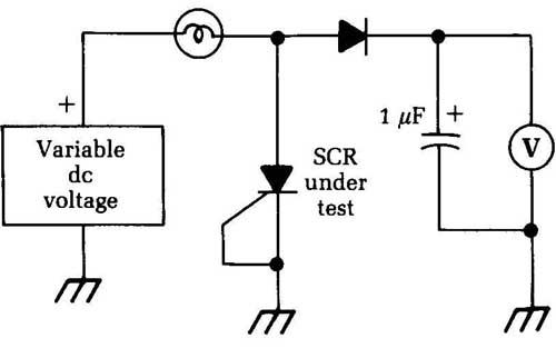
FIG. 28 The circuit for testing the V_drm, value for a SCR.
In practical SCR circuits, you also need to consider the re verse blocking voltage (Vrrm), the maximum voltage the SCR can withstand in its reverse-biased mode. It’s roughly equivalent to the peak reverse voltage (PRV) specification for an ordinary diode. If the reverse-biased voltage is exceeded, the SCR will go into avalanche and will start conducting heavily. If this condition is allowed to continue, the component could self-destruct.
FIG. 29 shows a circuit for testing a SCR’s Vrrm value. Notice that the power supply for this circuit must be a constant current source to prevent the SCR from burning itself out during the test procedure. A test that destroys the component being tested obviously would not be of much practical use.
Increase the voltage slowly until the SCR starts to avalanche and starts to conduct the reverse-biased current. The voltage indicated on the voltmeter at that point is the SCR’s Vrrm value.
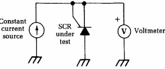
FIG. 29 The circuit for testing the V value for a SCR. Constant current source
Testing ICs
Integrated circuits (ICs) can be tricky for the troubleshooter. Essentially, you have to treat an IC as a black box. All that matters are the external functions. The internal circuitry is irrelevant since there is no way to get at it.
Test the supply voltages and the inputs to the IC. If these volt ages are correct but the outputs are wrong, it’s a good bet the IC is bad and should be replaced. However, sometimes you can be fooled by loading. Occasionally, a problem in a later stage can throw off the reading at the ICs output pin(s). If there is any possibility of this, break the connection between the output pin in question and the later stages of the circuit. If the IC is okay, you should now get a correct reading at the output pin.
Similarly, a bad IC sometimes can affect the value at one or more of its inputs. Again, the way to find out for sure is to break the connection to the appropriate pin and measure the signal that would be presented to the ICs input if the connection was not bro ken. If this signal is now correct, the IC is bad.
With IC-based equipment, a schematic is even more important than for other types of servicing jobs. The more you know about how the IC is supposed to work, the better chance you have for properly identifying any problems. Your work area should include as many IC data books as possible. Virtually all IC manufacturers supply data sheets, and many offer extensive data books on their products.
If there is a particular type of IC you deal with frequently, you might want to rig up a simple dedicated tester for that particular IC. The easiest way is to construct a simple circuit around the IC, using a socket. Then, just plug the questionable IC into the socket and apply power. If the circuit works, the IC is good.
Like transistors, ICs are usually either good or bad. It’s very unusual to find a weak IC, although it could conceivably happen. However, don’t consider such a possibility unless everything else has been ruled out. The best approach then is to simply replace the questionable Ic with a duplicate unit and hope for the best.
The test circuit should be as simple as possible. For example, if you work a lot with op amps, like the 741 and its descendants (which all have the same pin designations) you can put together a basic oscillator circuit with a small speaker as a tester. When you plug a good op amp IC into the socket and turn it on, a tone is produced by the speaker. This is a simple, clear-cut indication that things are working properly.
While on the subject of ICs, we should consider the question of sockets. Some experts swear by them, and others swear at them. IC sockets certainly make life easier on the service technician. ICs typically have 14 or 16 pins, and some have even more. Soldering (or resoldering) all of those tiny, closely spaced pins without creating solder bridges or overheating the delicate semi conductor crystal within the IC takes a sure, steady hand and fairly precise timing. It’s also a tedious job, especially desoldering.
If a socket can be used, you can pop out an IC and replace it in less than a minute, without even plugging in the soldering iron. The use of a special IC extraction tool is highly recommended to avoid bending or damaging the pins. Some technicians routinely add a socket whenever they replace an IC. Then, if a similar repair is ever needed, the job will be considerably easier.
Unfortunately, IC sockets are not an unmixed blessing. The electrical contact between the pins and the traces of the pc board is not quite as good as with soldered components. In the vast majority of circuits, this probably won’t make much difference. In some applications, however, especially those involving high frequencies, the use of a socket can lead to erratic operation. In portable equipment that can get knocked around, sockets are often undesirable. An IC can work its way out of its socket. It could get damaged. It could even short out some other part of the circuit, blowing out additional components. Finally, in many pieces of equipment, there just isn’t enough room for a socket.
Use your own judgment on whether or not to add IC sockets. Some equipment already has sockets from the manufacturer. In this case, just be grateful for the relative ease of repair. There’s no point in removing a socket installed by the manufacturer. (How ever, a socket added by another technician could conceivably be the source of problems in high-frequency circuits.)
You should exercise great care when replacing an IC, whether with a socket or not. Make sure the IC is correctly oriented. Applying power to a backward IC almost surely will result in disaster. Most ICs have a small notch indicating their “front” side, or they have a small dot over pin 1. Before removing an old IC, always make a note of its orientation.
When soldering an IC, be very careful. Don’t apply too much heat. The pins are very closely spaced, so it’s very easy to create an accidental solder bridge between two pins or adjacent pc traces. Never use too much solder and always heat-sink any IC before soldering it.
Make sure all of the pins go into the holes of the pc board or the socket. One might get bent up under the body of the IC. If this is not caught and corrected, there is a good chance the circuit won’t operate correctly.
It pays to be extra careful when working with ICs. For one thing, many of them are very expensive, especially recently developed or highly specialized devices. Mass manufacture tends to bring down the cost of general-purpose devices. However, it’s still smart to use extra caution even when replacing a “garden-variety” IC that only costs a quarter or fifty cents. Let’s face it, replacing an integrated circuit is a royal pain. There’s no reason to be careless to only end up having to do it over.
<< >>
