AMAZON multi-meters discounts AMAZON oscilloscope discounts
.
The first output meter used for aligning tube radios was an AC voltmeter across the speaker-voice coil. A 400 Hz AM signal was used. This was nice, but noisy. Today, of course, you can always unhook the speaker and substitute an equivalent resistor. An easier way is to use a VTVM on the avc line. The avc voltage developed across the diode detector is always directly proportionate to the amount of signal. This is a negative-going voltage, and you’ll find values from 1 V to 15 to 20 V.
FIG. 1 shows a typical avc circuit as used in tube radios. This one is rather elaborate. You’ll find fewer filter resistors and bypass capacitors in the smaller sets, but they all work the same way. The avc voltage appears at the top of the volume control, which is the diode load resistor. In most cases, you can pick up the avc at the mixer-grid section of the variable capacitor so you won’t have to take the set out of the case. It can be picked up at any point along the avc circuit. Since the avc circuit has a very high impedance, you’ll have to use a VTVM to get a readable deflection.
For best results, keep the input signal down to the point where it causes the smallest readable voltage on the avc; 1 V is a good average value. By doing so, you avoid the danger of over loading RF stages and flattening the response peaks.
Checking the calibration of an RF signal generator
Do you want to set your RF signal generator exactly on 455 kHz to realign the IF stages of a radio? Do you have doubts as to the accuracy of the generator’s calibration? Then use the most convenient source of highly accurate test signals—broadcast stations. All AM radio stations are required by the FCC to keep their carrier frequencies within ±20 Hz of their assigned frequency. Most of them hold to within ±5 Hz.
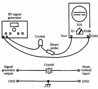
FIG. 1 A method for setting an RF signal generator on a crystal frequency.
RF signal generator; Crystal; Vert; Crystal; Signal generator output
To set your generator precisely on 455 kHz, get any radio that will pick up several stations. Its dial calibration doesn’t matter; you are only going to use the receiver as an indicator. Choose a station as close to 910 kHz as you can find. Listen to it long enough to determine the call letters and then look up the carrier frequency of the station. Tune the signal generator to 455 kHz and then zero-beat this with the station carrier, using an unmodulated RF output. Your generator’s second harmonic is beating with the station’s fundamental.
If you can’t find a station exactly on 910 kHz, locate one on each side as close as possible. Check each, note the error in the signal-generator dial. You can use this error to get the dial set on- frequency. For instance, if each station shows that the signal generator is one dial-marking low, then include this same amount of error when you set the generator for 455 kHz.
If you can’t find stations close enough to the right frequency, try the third harmonic. At a 455 kHz fundamental, this is 1,365 kHz, so use a broadcast station at 1,360 kHz (all radio stations are on even number 10 kHz apart).
For high-frequency checking, use standard-frequency stations WWV or (in Hawaii) WWVH. You need a communications receiver that covers to 30 MHz, but the actual dial calibration of the radio is not important. These stations broadcast accurate test signals at 2.5, 5, 10, 15, 20, and 25MHz. You can identify them easily by the 440 Hz beep tone, broken up by ticks at one-second intervals. Incidentally, these two stations also give standard time signals that are used the world over, in case you want to check your watch.
Setting an RF signal generator on a crystal frequency
Every now and then you need to set a signal generator to an exact frequency, either for alignment or calibration purposes, or to check the calibration of the signal generator. If you have a crystal that operates at or near the frequency you need, setting the generator is easy. Some signal generators have provisions for plugging in crystals, but you can use a crystal even with a generator that does not have these provisions.
Connect the crystal between the RF output of the signal generator and the vertical input of a scope using a direct probe, as illustrated in FIG. 1. Set the RF output to maximum and turn the scope’s vertical gain full up. Connect the ground leads of both instruments together, as shown. Now tune the signal generator very slowly back and forth over the frequency of the crystal. When you hit the exact frequency, you’ll see the scope pattern increase in height.
The crystal is acting as a very sharp resonant filter. When you hit the right frequency, the RF voltage developed across it rises sharply; in typical tests, it might go from .05 to 0.5 Vp-p. The scope need not be a wideband type; all you are looking for is an increase in pattern height. You’ll have to tune the signal generator very slowly because the point of resonance is very sharp and you might pass it.
You can use an ac VTVM instead of the scope, or the DC-VOLTS range of a VTVM with a diode in series with the probe. The polarity of the voltage you read depends on how the diode is connected, but this isn’t important; all you want is the peak.
You also can hook the crystal up in shunt: Connect the RF output lead and the scope input lead together, connect the ground leads together, and hook the crystal across them. Now you’ll see a pattern on the scope (or a voltage on the meter) at all times. When you hit the crystal frequency, you’ll see a very sharp dip in the pattern height or in the voltage reading.
When adjusted to the peak (crystal in series) or the dip (crystal in shunt), the signal generator is tuned to the frequency of the crystal and can be used as a standard for aligning RF or IF stages, receivers, or whatever is necessary. This test works pretty well with crystals up to 4.5 to 5 MHz, but above this frequency you usually run into low output from signal generators (the average signal generator uses harmonics in the VHF range, thus reducing the output by half or more). Therefore, there isn’t enough RF power to get a usable reading on an indicator. The test would still work, with some kind of an amplifier or booster to get the output up to a readable level.
Although it isn’t too reliable, this test can serve as an indicator of crystal output or activity (a broken or bad crystal won’t respond at all). It also will roughly identify the frequency range of unknown crystals. If you test a crystal and get more than one reading, you can still identify the fundamental frequency of the crystal. It will make a deeper dip or give a higher output (in the series test) than any harmonic.
Finding the exact point of a zero beat
When checking radio frequencies, you often want to find the exact frequency of a signal or set the bench signal generator exactly on a given frequency. To do so, check against a standard frequency of known accuracy. The easiest way is by zero-beating the unknown signal with the standard. All you need is a radio receiver that picks up the standard frequency. The standard itself can come from an accurate RF signal generator, from radio station WWV, etc. The receiver doesn’t have to be accurately calibrated; it serves only as an indicator—a device for making the two frequencies beat against each other.
By ear alone, it’s often hard to tell where the exact zero point of zero beat is. So hook an output meter (an ac voltmeter) to the radio output, as shown in FIG. 2. Next, couple the signal genera tor to be checked to the antenna of the radio, along with the standard. Sometimes just clipping its output lead to the insulation of the antenna lead is enough. Tune this signal to the test frequency, listening for a zero beat in the receiver output as you tune. As the unknown signal approaches the frequency of the standard, you will hear a high-pitched tone that gradually goes lower as you get closer until you can’t hear it at all. It then starts to go higher again as you tune past the standard.
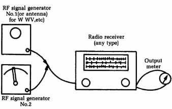
FIG. 2 To find the exact point of a zero beat, connect an ac voltmeter to
the radio’s output. RF signal generator No.1(or antenna) for W WV, etc); RF
signal generator; No. 2; Output meter; Radio receiver (any type)
Since the beat frequency goes down to zero, below the audible range, the exact zero point is hard to detect by ear. If you want to be very precise, tune for the lowest audible beat frequency and start watching the meter. When you reach a very low frequency, you’ll see the meter needle start to wiggle as it tries to follow the beat note. At the same time, it will swing slower and slower. Tune for where the needle moves slowest.
Test records: Good substitutes for the audio-signal generator
The average shop needs a high-quality audio-frequency signal generator, but seldom has one. It has to make-do with the 400 Hz audio output of an RF signal generator, although this will do the job for signal tracing and such work. However, you can get any kind of audio test signal you need at a very low cost, compared to the $300 or more for a high-quality AF generator. The source is a test record, and a great many different types are available— stereo, mono, or a combination of the two. With a suitable test record and an inexpensive record player, you’re ready for almost any kind of audio work.
A typical test record has single-frequency bands for checking distortion or stylus wear, and a frequency-run series from 30 Hz up to 20 kHz. For stereo, it has left signal, right signal, and both for speaker phasing. Most test records also have many other frequencies. The single-channel stereo signals are very handy for checking separation, etc., and even for identifying channels.
In most cases, you won’t even need an audio amplifier; the modern crystal cartridge has an output of up to 3 to 4 V, which can be fed directly into many audio circuits. If you want to, you can pick up a small, used amplifier to supply output signals up to 30 to 40 V for checking speakers and signal tracing in high-power AF stages, etc. This amplifier needn’t be hi-fl. You can use it to get the amplifier being tested into working condition, and then feed a signal directly from the cartridge into the input for distortion checks of the complete system with a scope.
Using radio signals for testing hi-fi or PA systems
When testing hi-fl, stereo, or PA-system amplifiers, use a radio station as a signal source to let the amplifier “cook” for a while after repairing.
The input stage of the average high-gain audio amplifier acts as a detector for RF signals. Hook your TV antenna right across the input, as shown in FIG. 3 ( you must have a closed circuit here). The lead-in and dipole make up a sort of long-loop antenna. Any thing like a conical antenna , for example, which has no continuity across the lead-in, won’t work; you’d get a tremendous buzz or hum.
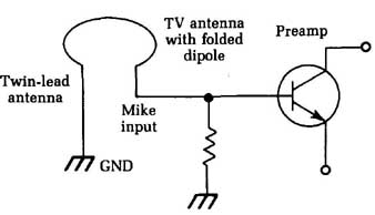
FIG. 3 This circuit permits the use of radio signals for testing stereo or
PA systems. TV antenna with folded dipole; Preamp; Twin-lead antenna.
This technique works best if there’s a local radio station near enough to put a good signal into your shop area. If the signal is too weak, however, you can pick up music from a surprising distance by adding a detector diode in series with one side of the lead-in, or in shunt across the input.
If you have several strong locals, this system won’t give a single clear sound. An alternative is to pick up the audio from the volume control of a small radio (either tube or transistor). You can set the gain wherever you want it and listen to the music as you cook the amplifier.
Using a communications receiver as an RF signal locator or tracer
Every now and then you need an instrument that can find or trace an RF signal through a circuit, identify an unknown RF frequency, or signal-trace through a circuit to find where the trouble is located. There are special signal-tracing test instruments, but a standard communications receiver (of the kind we used to call a short-wave set) will do the job nicely.
Such receivers have antenna inputs that can be used on di pole antennas or convert to match 75 1 coaxial cable; a shorting link on the antenna terminal board is used to make the conversion, as shown in FIG. 4. Get a piece of RG59/U coaxial cable 3 to 4 feet long and prepare one end to hook up to the terminal board.
Communications receiver; Shield; Inner conductor; Antenna terminal board: D,D, GND; RG59/U Cable; 1” of inner conductor insulated; Shield cut back
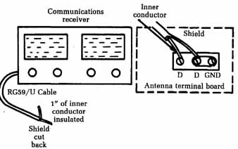
FIG. 4 A home-made probe for an RF signal locator or tracer.
Cut off about 1 inch of the shield braid on the other end, exposing the insulated inner conductor. Don’t take the insulation off; pull it out over the tip of the inner conductor so the wire can’t make contact with anything.
Now, you can find and identify any RF signal within the tuning range of the receiver. For example, if you’re checking a high-frequency oscillator circuit and want to know whether it’s working on the right frequency—or working at all , for that matter — simply put the probe end of the cable close to the circuit and tune for the oscillator signal on the receiver dial. You can bend the end of the probe cable into a little hook that can be hooked over wires, etc., near the circuit under test.
An unmodulated RF signal sounds like a little thump in the speaker when tuned across. Tuned directly on it, you hear a rushing sound. A better way to identify it’s to turn on the receiver’s beat-frequency oscillator (bfo). Now if you cross an RF signal, you’ll hear the characteristic beat note or sequel.
For an indication of the strength of the signal, hook a dc VTVM to the test receiver’s avc circuit. For convenience, run a lead from the avc to a jack on the receiver panel or back apron, etc., and connect the VTVM there. If the receiver doesn’t have avc, use the dc voltage developed across the audio detector; this is usually where the avc voltage comes from anyway. The voltage will go more negative as the input signal strength increases.
A receiver with a probe and an avc meter attached makes a handy little alignment indictor. For example, if you are tuning up an RF amplifier stage, feed in a signal at the desired frequency, tune the RF stage to it, and then pick up the RF signal output at the mixer grid with the probe. Now, you can adjust the input signal to a very low level to really sharpen the tuning of the RF stages.
You also can follow an RF signal through these stages to determine if it’s getting through, to see if there is a loss or gain in each stage, and to make many tests that are impossible with other test equipment. The probe won’t seriously detune any stage be cause it should never make actual contact. Because of the sensitivity of the test receiver, the probe picks up plenty of signal when it’s placed near any circuit.
You can use this method for netting CB transceivers — that is, tuning all transmitters and receivers in a system exactly to each others’ frequency. Tune the test receiver to the CB transmitter by keying the transmitter and tuning for maximum avc voltage. Next, tune your RF signal generator to the same frequency in the same way. Now feed the signal from the RF generator into the CB receiver, and tune it up for maximum output. You can use the test receiver as an output indicator by picking up the IF signal at the CB audio detector or you can use a scope or output meter. The CB transmitter itself can be used for this of course, but the RF signal generator will do a better job because its output can be controlled. Always make this kind of alignment adjustment on the smallest possible RF signal to avoid flattening the response curves or over loading the high-gain RF circuits.
In some VHF receivers, such as in two-way FM systems, frequency multiplication can be used to produce a VHF frequency from a low-frequency crystal oscillator. These receivers can be very confusing if you’re not sure the multiplier coils are tuned to the correct harmonic! Set the dial of the test receiver to the correct harmonic frequency, hook the probe over the output lead of the multiplier coil, and tune for maximum.
Using an ac voltmeter for gain checks and signal tracing
The ac voltmeter can be a handy instrument. The standard rectifier-type voltmeter has a good frequency range, making it especially useful for gain checks and signal tracing in audio amplifiers.
Feed an audio signal—about 400 Hz—into the input of an audio amplifier. Put a blocking capacitor of any size from 0.01 to 0.1 uF in series with the meter. (Rectifier-type meters are affected by dc; the capacitor blocks any dc and lets you read only ac or signal voltages.) Now you can start at either end of the amplifier and trace the signal through each stage to find out whether there is gain or loss.
This test is handy in amplifiers that are weak, but not dead. It’s a rapid way to find the defective stage in a dead amplifier, too. Simply run through the circuit until you find the stage that has signal on the input but none on the output, and there you are.
This technique works with tubes or transistors and is especially useful in transistorized PC-board circuits. By using signal tracing first, you save the trouble of making voltage measurements and unsoldering parts before you have actually found the defective stage. The basic thing to check for is small signal on the input (base or grid) and a larger signal on the output (plate or collector), which would indicate that the stage does have gain. When you find a stage with no gain, or with a loss, that’s the faulty one.
There is one exception to this rule in tube circuits and, to some extent, in transistors: the split-load phase inverter. As a rule, this stage is not designed to have any gain, but merely to di vide and invert the signal. In the tube circuit, the load resistance is divided equally between the plate and cathode circuits. Thus, equal signal voltages appear on the two elements, but one signal is 1800 out of phase with the other. There are several transistor circuits that do the same thing. To check for proper operation of such a circuit, measure the signal voltages on the input elements (grids or bases) of the following push-pull stage. The two signals should always be equal in amplitude. You can’t check the phase without a scope, but chances are, if the signals are of equal amplitude, everything else is okay.
The ac voltmeter is also handy for finding troubles in stereo amplifiers. Feed the same audio signal into both inputs at the same time. Now measure the signal levels in corresponding stages of the two channels. At a given point, if you find one channel with a much lower signal than the other, that’s the source of the trouble. Use the good channel as a guinea-pig to find out where the trouble is in the other channel.
The gain setting must be the same in both channels to prevent confusion. A good procedure is to turn both gain controls full on and then reduce the input signal level until the output level is about right. Don’t overdrive; most stereo amplifiers have high gain and need only a small input signal. For the average phono input, 1 or 2 V is plenty; for a microphone input, much less will do —0.005 volt or less. Very high input signals can cause severe distortion or even damage transistors.
Power output tests for PA and hi-fi amplifiers
Check the power output of PA amplifiers and hi-fis to see if that 30 W amplifier is actually able to deliver 30 W output. There is a simple test. After you have completed repairs and the amplifier is theoretically in first-class shape, hook up a properly matched load resistor across the output, feed in an audio signal, and read the power output by measuring the audio voltage across the load resistor. Ohm’s law does the rest.
FIG. 5 shows how the equipment is set up for this test procedure. You need a resistor that matches the output impedance of the amplifier and has a rating high enough to handle the power, with a safety factor. For a 30 W amplifier, a 50W resistor is good. You can get such resistors from surplus stores at reasonable prices. Otherwise, make them up from stock values. For instance, PA and hi-fl tube amplifiers usually have output transformers tapped at 4, 8, 16, and 500 ohm. Five 75 ohm low resistors in parallel give 15 ohm at 50 W (for equal resistors, power ratings are totaled), and this is close enough for the 16 ohm tap. Five 2,500 ohm resistors in parallel give 500 ohm, etc.
With the load resistor hooked up, feed a low-level audio signal into the input; 1,000 Hz is a good frequency since most audio measurements are made at this frequency. Actually, the frequency doesn’t make too much difference, as long as you’re some where between 500 Hz and 5,000 or 6,000 Hz. (On most transistor amplifiers, especially the older ones, don’t feed in a high-frequency signal — say, 15,000Hz — at high power. The output transistors will overheat.) Remember this precaution: Never turn on an amplifier without the load resistor of the speaker hooked up. Even in tube amplifiers, you can burn out the output transformer in a very short time, and transistors can go in a fraction of a second if they are run without the proper load. Never short transistor outputs!
The service data gives the correct input level for many amplifiers. However, you are in the power output stage; can it deliver the rated power? To find out, hook an ac voltmeter across the load resistor and fire up the amplifier. If you’re using a 15 ohm resistor and the amplifier is rated at 30w , for example, you should read at least 21 V. Using W = E and transposing to calculate E, you get F = 30 x 15, which yields about 21 V for E.
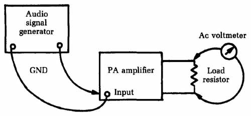
FIG. 5 The setup for testing the power output of a stereo or PA amplifier.
This is also a good voltage-amplification or sensitivity check. For example, on a phono input, you should get full power with the normal input level. With a high-output phono cartridge, this would be about a 2 V input signal. On a low-output microphone, it would be about 5 mV, etc. If you can get full output only by over driving the input to two or three times normal, then one of the voltage amplifier stages isn’t giving enough gain.
<< >>
