AMAZON multi-meters discounts AMAZON oscilloscope discounts
1. INTRODUCTION
Measurement is the act, or the result, of a quantitative comparison between a given quantity and a quantity of the same kind chosen as a unit. The result of the measurement is expressed by a pointer deflection over a predefined scale or a number representing the ratio between the unknown quantity and the standard. A standard is defined as the physical personification of the unit of measurement or its sub-multiple or multiple values. The device or instrument used for comparing the unknown quantity with the unit of measurement or a standard quantity is called a measuring instrument. The value of the unknown quantity can be measured by direct or indirect methods. In direct measurement methods, the unknown quantity is measured directly instead of comparing it with a standard. Examples of direct measurement are current by ammeter, voltage by voltmeter, resistance by ohmmeter, power by wattmeter, etc. In indirect measurement methods, the value of the unknown quantity is determined by measuring the functionally related quantity and calculating the desired quantity rather than measuring it directly. Suppose the resistance as ( R ) of a conductor can be measured by measuring the voltage drop across the conductor and dividing the voltage ( V ) by the current ( I ) through the conductors, by Ohm's law.
2. FUNDAMENTAL AND DERIVED UNITS
At the time of measuring a physical quantity, we must express the magnitude of that quantity in terms of a unit and a numerical multiplier, i.e., Magnitude of a physical quantity = (Numerical ratio) × (Unit)
The numerical ratio is the number of times the unit occurs in any given amount of the same quantity and, therefore, is called the number of measures. The numerical ratio may be called numerical multiplier. However, in measurements, we are concerned with a large number of quantities which are related to each other, through established physical equations, and therefore the choice of size of units of these quantities cannot be done arbitrarily and independently. In this way, we can avoid the use of awkward numerical constants when we express a quantity of one kind which has been derived from measurement of another quantity.
In science and engineering, two kinds of units are used:
• Fundamental units
• Derived units
The fundamental units in mechanics are measures of length, mass and time. The sizes of the fundamental units, whether foot or meter, pound or kilogram, second or hour are arbitrary and can be selected to fit a certain set of circumstances. Since length, mass and time are fundamental to most other physical quantities besides those in mechanics, they are called the primary fundamental units. Measures of certain physical quantities in the thermal, electrical and illumination disciplines are also represented by fundamental units.
These units are used only when these particular classes are involved, and they may therefore be defined as auxiliary fundamental units.
All other units which can be expressed in terms of the fundamental units are called derived units. Every derived unit originates from some physical law defining that unit. For example, the area ( A ) of a rectangle is proportional to its length ( l ) and breadth ( b), or A = lb. if the meter has been chosen as the unit of length then the area of a rectangle of 5 meters by 7 meters is 35 m^2 . Note that the numbers of measure are multiplied as well as the units. The derived unit for area ( A ) is then the meter square (m^2 ).
A derived unit is recognized by its dimensions, which can be defined as the complete algebraic formula for the derived unit. The dimensional symbols for the fundamental units of length, mass and time are L, M and T respectively. The dimensional symbol for the derived unit of area is L^2 and that for volume is L^3 . The dimensional symbol for the unit of force is MLT , which follows from the defining equation for force. The dimensional formulas of the derived units are particularly useful for converting units from one system to another. For convenience, some derived units have been given new names. For example, the derived unit of force in the SI system is called the newton (N), instead of the dimensionally correct kg-m/s^2 .
3. STANDARDS AND THEIR CLASSIFICATIONS
A standard of measurement is a physical representation of a unit of measurement. A unit is realised by reference to an arbitrary material standard or to natural phenomena including physical and atomic constants. The term 'standard' is applied to a piece of equipment having a known measure of physical quantity. For example, the fundamental unit of mass in the SI system is the kilogram, defined as the mass of the cubic decimeter of water at its temperature of maximum of 4°C. This unit of mass is represented by a material standard; the mass of the international prototype kilogram consisting of a platinum-iridium hollow cylinder. This unit is preserved at the International Bureau of Weights and Measures at Sevres, near Paris , and is the material representation of the kilogram. Similar standards have been developed for other units of measurement, including fundamental units as well as for some of the derived mechanical and electrical units.
The classifications of standards are:
1. International standards
2. Primary standards
3. Secondary standards
4. Working standards
5. Current standards
6. Voltage standards
7. Resistance standards
8. Capacitance standards
9. Time and frequency standards
3.1 International Standards
The international standards are defined by international agreement. They represent certain units of measurement to the closest possible accuracy that production and measurement technology allow. International standards are periodically checked and evaluated by absolute measurements in terms of the fundamental units. These standards are maintained at the International Bureau of Weights and Measures and are not available to the ordinary user of measuring instruments for purposes of comparison or calibration. Table 1 shows basic SI Units, Quantities and Symbols.
Table 1 Basic Quantities, SI Units and Symbols
3.2 Primary Standards
The primary standards are maintained by national standards laboratories in different places of the world. The National Bureau of Standards (NBS) in Washington is responsible for maintenance of the primary standards in North America . Other national laboratories include the National Physical Laboratory (NPL) in Great Britain and the oldest in the world, the Physikalisch Technische Reichsanstalt in Germany . The primary standards, again representing the fundamental units and some of the derived mechanical and electrical units, are independently calibrated by absolute measurements at each of the national laboratories. The results of these measurements are compared with each other, leading to a world average figure for the primary standard. Primary standards are not available for use outside the national laboratories. One of the main functions of primary standards is the verification and calibration of secondary standards.
3.3 Secondary Standards
Secondary standards are the basic reference standards used in the industrial measurement laboratories. These standards are maintained by the particular involved industry and are checked locally against other reference standards in the area. The responsibility for maintenance and calibration rests entirely with the industrial laboratory itself. Secondary standards are generally sent to the national standards laboratory on a periodic basis for calibration and comparison against the primary standards. They are then returned to the industrial user with a certification of their measured value in terms of the primary standard.
3.4 Working Standards
Working standards are the principle tools of a measurement laboratory. They are used to check and calibrate general laboratory instruments for accuracy and performance or to perform comparison measurements in industrial applications. A manufacturer of precision resistances, for example, may use a standard resistor in the quality control department of his plant to check his testing equipment. In this case, the manufacturer verifies that his measurement setup performs within the required limits of accuracy.
3.5 Current Standard
The fundamental unit of electric current (Ampere) is defined by the International System of Units (SI) as the constant current which, if maintained in two straight parallel conductors of infinite length and negligible circular cross section placed 1 meter apart in vacuum, will produce between these conductors a force equal to 2 × 10^-7 newton per meter length. Early measurements of the absolute value of the ampere were made with a current balance which measured the force between two parallel conductors. These measurements were rather crude and the need was felt to produce a more practical and reproducible standard for the national laboratories. By international agreement, the value of the international ampere was based on the electrolytic deposition of silver from a silver nitrate solution. The international ampere was then defined as that current which deposits silver at the rate of 1.118 mg/s from a standard silver nitrate solution. Difficulties were encountered in the exact measurement of the deposited silver and slight discrepancies existed between measurements made independently by the various National Standard Laboratories. Later, the international ampere was superseded by the absolute ampere and it is now the fundamental unit of electric current in the SI and is universally accepted by international agreement.
3.6 Voltage Standard
In early times, the standard volt was based on an electrochemical cell called the saturated standard cell or simply standard cell. The saturated cell has temperature dependence, and the output voltage changes about -40 μV/°C from the nominal of 1.01858 volt. The standard cell suffers from this temperature dependence and also from the fact that the voltage is a function of a chemical reaction and not related directly to any other physical constants. In 1962, based on the work of Brian Josephson, a new standard for the volt was introduced. A thin-film junction is cooled to nearly absolute zero and irradiated with microwave energy. A voltage is developed across the junction, which is related to the irradiating frequency by the following relationship:
where, h =Planck's constant = 6.63 × 10^-34 J-s
e =charge of an electron = 1.602 × 10^-19 C
f =frequency of the microwave irradiation
In Eq. (1), the irradiation frequency is the only variable, thus the standard volt is related to the standard of time/frequency. When the microwave irradiating frequency is locked to an atomic clock or a broadcast frequency standard such as WWVB, the accuracy of the standard volt, including all of the system inaccuracies, is one part in 10^8 .
The major method of transferring the volt from the standard based on the Josephson junction to secondary standards used for calibration of the standard cell. This device is called the normal or saturated Weston cell. The Weston cell has a positive electrode of mercury and a negative electrode of cadmium amalgam (10% cadmium). The electrolyte is a solution of cadmium sulfate. These components are placed in an H-shaped glass container as shown in FIG. 1 .
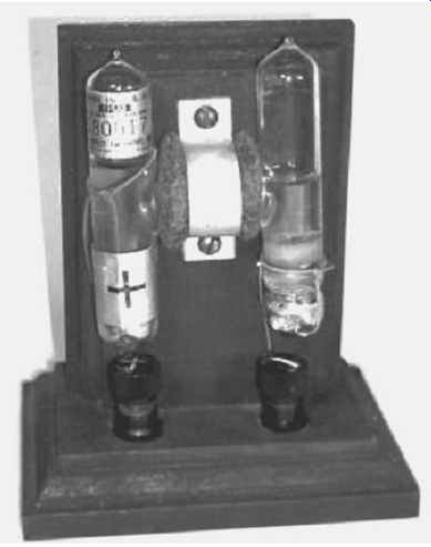
FIG. 1 Standard cell of emf of 1.0183 volt at 20°C
(Courtesy, physics.kenyon.edu )
3.7 Resistance Standard
In the SI system, the absolute value of ohm is defined in terms of the fundamental units of length, mass and time. The absolute measurement of the ohm is carried out by the International Bureau of Weights and Measures in Sevres and also by the national standard laboratories, which preserve a group of primary resistance standards. The NBS maintains a group of those primary standards (1 ohm standard resistors) which are periodically checked against each other and are occasionally verified by absolute measurements. The standard resistor is a coil of wire of some alloy like manganin which has a high electrical resistivity and a low temperature coefficient of resistance. The resistance coil is mounted in a double walled sealed container as shown in FIG. 2 to prevent changes in resistance due to moisture conditions in the atmosphere. With a set of four or five 1-ohm resistors in this type, the unit resistance can be represented with a precision of a few parts in 10^7 over several years.
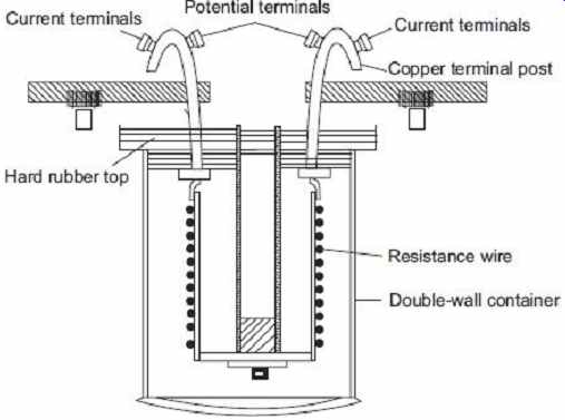
FIG. 2 Resistance standard
Secondary standards and working standards are available from some instrument manufactures in a wide range of values, usually in multiples of 10 ohms. These standard resistors are sometimes called transfer resistor and are made of alloy resistance wire, such as manganin or Evanohm. The resistance coil of the transfer resistor is supported between polyester films to reduce stresses on the wire and to improve the stability of the resistor.
The coil is immersed in moisture free oil and placed in a sealed container. The connections to the coil are silver soldered, and the terminal hooks are made of nickel-plated oxygen free copper. The transfer resistor is checked for stability and temperature characteristics at its rated power and a specified operating temperature (usually 25°C). A calibration report accompanying the resistor specifies its traceability to NBS standards and includes the a and β temperature coefficients. Although the selected resistance wire provides almost constant resistance over a fairly wide temperature range, the exact value of the resistance at any temperature can be calculated from the formula
R t = R 25°C + α ( t - 25) + β ( t - 25)^2
where R t = resistance at the ambient temperature t
R 25°C = resistance at 25°c
α,β = temperature coefficients
Temperature coefficient a is usually less than 10 × 10 - , and coefficient β lies between -3 × 10 - to -6 × 10^-7 . This means that a change in temperature of 10°C from the specified reference temperature of 25°C may cause a change in resistance of 30 to 60 ppm from the nominal value.
3.8 Capacitance Standard
Many electrical and magnetic units may be expressed in terms of these voltage and resistance standards since the unit of resistance is represented by the standard resistor and the unit of voltage by standard Weston cell. The unit of capacitance (the farad) can be measured with a Maxwell dc commutated bridge, where the capacitance is computed from the resistive bridge arms and the frequency of the dc commutation. The bridge is shown in FIG. 3 . Capacitor C is alternately charged and discharged through the commutating contact and resistor R. Bridge balance is obtained by adjusting the resistance R 3 , allowing exact determination of the capacitance value in terms of the bridge arm constants and frequency of commutation. Although the exact derivation of the expression for capacitance in terms of the resistances and the frequency is rather involved, it may be seen that the capacitor could be measured accurately by this method. Since both resistance and frequency can be determined very accurately, the value of the capacitance can be measured with great accuracy. Standard capacitors are usually constructed from interleaved metal plates with air as the dielectric material. The area of the plates and the distance between them must be known very accurately, and the capacitance of the air capacitor can be determined from these basic dimensions. The NBS maintains a bank of air capacitors as standards and uses them to calibrate the secondary and working standards of measurement laboratories and industrial users.
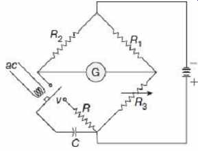
FIG. 3 Commutated dc method for measuring capacitance
3.9 Time Standard and Frequency Standard
In early centuries the time reference used was the rotation of the earth around the sun about its axis. Later, precise astronomical observations have shown that the rotation of the earth around the sun is very irregular, owing to secular and irregular variations in the rotational speed of the earth. So the time scale based on this apparent solar time had to be changed. Mean solar time was thought to give a more accurate time scale. A mean solar day is the average of all the apparent days in the year. A mean solar second is then equal to 1/86400 of the mean solar day. The mean solar second is still inappropriate since it is based on the rotation of the earth which is non-uniform.
In the year 1956, the ephemeris second has been defined by the International Bureau of Weights and Measures as the fraction 1/31556925.99747 of the tropical year for 1900 January 01 at 12 h ET (Ephemeris Time), and adopted as the fundamental invariable unit of time. A disadvantage of the use of the ephemeris second is that it can be determined only several years in arrears and then only indirectly, by observations of the positions of the sun and the moon. For physical measurements, the unit of time interval has now been defined in terms of an atomic standard. The universal second and the ephemeris second, however, will continue to be used for navigation, geodetic surveys and celestial mechanics. The atomic units of the time was first related to UT (Universal Time) but was later expressed in terms of ET. The International Committee of Weights and Measures has now defined the second in terms of frequency of the cesium transition, assigning a value of 9192631770 Hz to the hyperfine transition of the cesium atom unperturbed by external fields.
The atomic definition of second realizes an accuracy much greater than that achieved by astronomical observations, resulting in a more uniform and much more convenient time base. Determinations of time intervals can now be made in a few minutes to greater accuracy than was possible before in astronomical measurements that took many years to complete. An atomic clock with a precision exceeding 1 μs per day is in operation as a primary frequency standard at the NBS. An atomic time scale, designated NBS-A, is maintained with this clock.
Time and frequency standards are unique in that they may be transmitted from the primary standard at NBS to other locations via radio or television transmission. Early standard time and frequency transmission were in the High Frequency (HF) portion of the radio spectrum, but these transmissions suffered from Doppler shifts due to the fact that radio propagation was primarily ionospheric. Transmission of time and frequency standards via low frequency and very low frequency radio reduces this Doppler shift because the propagation is strictly ground wave. Two NBS operated stations, WWVL and WWVB, operate 20 and 60 kHz, respectively, providing precision time and frequency transmissions.
4. METHODS OF MEASUREMENT
As discussed above, the measurement methods can be classified as
• Direct comparison methods
• Indirect comparison methods
4.1 Direct Comparison Methods
In direct measurement methods, the unknown quantity is measured directly. Direct methods of measurement are of two types, namely, deflection methods and comparison methods.
In deflection methods, the value of the unknown quantity is measured by the help of a measuring instrument having a calibrated scale indicating the quantity under measurement directly, such as measurement of current by an ammeter.
In comparison methods, the value of the unknown quantity is determined by direct comparison with a standard of the given quantity, such as measurement of emf by comparison with the emf of a standard cell. Comparison methods can be classified as null methods, differential methods, etc. In null methods of measurement, the action of the unknown quantity upon the instrument is reduced to zero by the counter action of a known quantity of the same kind, such as measurement of weight by a balance, measurement of resistance, capacitance, and inductance by bridge circuits.
In indirect measurement methods, the comparison is done with a standard through the use of a calibrated system. These methods for measurement are used in those cases where the desired parameter to be measured is difficult to be measured directly, but the parameter has got some relation with some other related parameter which can be easily measured.
For instance, the elimination of bacteria from some fluid is directly dependent upon its temperature. Thus, the bacteria elimination can be measured indirectly by measuring the temperature of the fluid.
In indirect methods of measurement, it is general practice to establish an empirical relation between the actual measured quantity and the desired parameter.
The different methods of measurement are summarized with the help of a tree diagram in FIG. 4 .
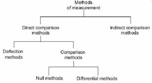
FIG. 4 Different methods of measurement
5. MEASUREMENT SYSTEM AND ITS ELEMENTS
A measurement system may be defined as a systematic arrangement for the measurement or determination of an unknown quantity and analysis of instrumentation. The generalized measurement system and its different components/elements are shown in FIG. 5.
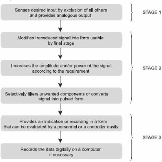
FIG. 5 Generalized measurement system
The operation of a measurement system can be explained in terms of functional elements of the system. Every instrument and measurement system is composed of one or more of these functional elements and each functional element is made of distinct components or groups of components which performs required and definite steps in measurement. The various elements are the following:
5.1 Primary Sensing Elements
It is an element that is sensitive to the measured variable. The physical quantity under measurement, called the measurand, makes its first contact with the primary sensing element of a measurement system. The measurand is always disturbed by the act of the measurement, but good instruments are designed to minimize this effect. Primary sensing elements may have a non-electrical input and output such as a spring, manometer or may have an electrical input and output such as a rectifier. In case the primary sensing element has a non-electrical input and output, then it is converted into an electrical signal by means of a transducer. The transducer is defined as a device, which when actuated by one form of energy, is capable of converting it into another form of energy.
Many a times, certain operations are to be performed on the signal before its further transmission so that interfering sources are removed in order that the signal may not get distorted. The process may be linear such as amplification, attenuation, integration, differentiation, addition and subtraction or nonlinear such as modulation, detection, sampling, filtering, chopping and clipping, etc. The process is called signal conditioning.
So a signal conditioner follows the primary sensing element or transducer, as the case may be. The sensing element senses the condition, state or value of the process variable by extracting a small part of energy from the measurand, and then produces an output which reflects this condition, state or value of the measurand.
5.2 Variable Conversion Elements
After passing through the primary sensing element, the output is in the form of an electrical signal, may be voltage, current, frequency, which may or may not be accepted to the system. For performing the desired operation, it may be necessary to convert this output to some other suitable form while retaining the information content of the original signal. For example, if the output is in analog form and the next step of the system accepts only in digital form then an analog-to-digital converter will be employed. Many instruments do not require any variable conversion unit, while some others require more than one element.
5.3 Manipulation Elements
Sometimes it is necessary to change the signal level without changing the information contained in it for the acceptance of the instrument. The function of the variable manipulation unit is to manipulate the signal presented to it while preserving the original nature of the signal. For example, an electronic amplifier converts a small low voltage input signal into a high voltage output signal. Thus, the voltage amplifier acts as a variable manipulation unit. Some of the instruments may require this function or some of the instruments may not.
5.4 Data Transmission Elements
The data transmission elements are required to transmit the data containing the information of the signal from one system to another. For example, satellites are physically separated from the earth where the control stations guiding their movement are located.
5.5 Data Presentation Elements
The function of the data presentation elements is to provide an indication or recording in a form that can be evaluated by an unaided human sense or by a controller. The information regarding measurand (quantity to be measured) is to be conveyed to the personnel handling the instrument or the system for monitoring, controlling or analysis purpose.
Such a device may be in the form of analog or digital format. The simplest form of a display device is the common panel meter with some kind of calibrated scale and pointer.
In case the data is to be recorded, recorders like magnetic tapes or magnetic discs may be used. For control and analysis purpose, computers may be used.
The stages of a typical measurement system are summarized below with the help of a flow diagram in FIG. 6 .
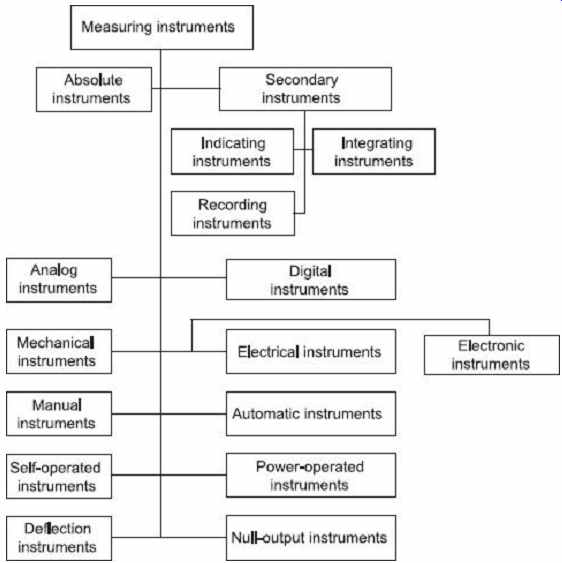
FIG. 6 Steps of a typical measurement system