AMAZON multi-meters discounts AMAZON oscilloscope discounts
(cont. from part 1)
6. CLASSIFICATION OF INSTRUMENTS
The measuring instruments may be classified as follows:
6.1 Absolute and Secondary Instruments
1. Absolute Instruments
The instruments of this type give the value of the measurand in terms of instrument constant and its deflection. Such instruments do not require comparison with any other standard. The example of this type of instrument is tangent galvanometer, which gives the value of the current to be measured in terms of tangent of the angle of deflection produced, the horizontal component of the earth's magnetic field, the radius and the number of turns of the wire used. Rayleigh current balance and absolute electrometer are other examples of absolute instruments. Absolute instruments are mostly used in standard laboratories and in similar institutions as standardizing. The classification of measuring instruments is shown in FIG. 7 .
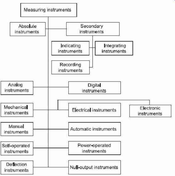
FIG. 7 Classification of measuring instruments
2. Secondary Instruments
These instruments are so constructed that the deflection of such instruments gives the magnitude of the electrical quantity to be measured directly. These instruments are required to be calibrated by comparison with either an absolute instrument or with another secondary instrument, which has already been calibrated before the use. These instruments are generally used in practice.
Secondary instruments are further classified as
• Indicating instruments
• Integrating instruments
• Recording instruments
(i) Indicating Instruments
Indicating instruments are those which indicate the magnitude of an electrical quantity at the time when it is being measured. The indications are given by a pointer moving over a calibrated (pregraduated) scale. Ordinary ammeters, voltmeters, wattmeters, frequency meters, power factor meters, etc., fall into this category.
(ii) Integrating Instruments
Integrating instruments are those which measure the total amount of either quantity of electricity (ampere-hours) or electrical energy supplied over a period of time. The summation, given by such an instrument, is the product of time and an electrical quantity under measurement. The ampere-hour meters and energy meters fall in this class.
(iii) Recording Instruments
Recording instruments are those which keep a continuous record of the variation of the magnitude of an electrical quantity to be observed over a definite period of time. In such instruments, the moving system carries an inked pen which touches lightly a sheet of paper wrapped over a drum moving with uniform slow motion in a direction perpendicular to that of the direction of the pointer. Thus, a curve is traced which shows the variations in the magnitude of the electrical quantity under observation over a definite period of time.
Such instruments are generally used in powerhouses where the current, voltage, power, etc., are to be maintained within certain acceptable limit.
6.2 Analog and Digital Instruments
1. Analog Instruments
The signals of an analog unit vary in a continuous fashion and can take on infinite number of values in a given range. Fuel gauge, ammeter and voltmeters, wrist watch, speedometer fall in this category.
2. Digital Instruments
Signals varying in discrete steps and taking on a finite number of different values in a given range are digital signals and the corresponding instruments are of digital type.
Digital instruments have some advantages over analog meters, in that they have high accuracy and high speed of operation. It eliminates the human operational errors. Digital instruments can store the result for future purposes. A digital multimeter is the example of a digital instrument.
6.3 Mechanical, Electrical and Electronics Instruments
1. Mechanical Instruments
Mechanical instruments are very reliable for static and stable conditions. They are unable to respond rapidly to the measurement of dynamic and transient conditions due to the fact that they have moving parts that are rigid, heavy and bulky and consequently have a large mass. Mass presents inertia problems and hence these instruments cannot faithfully follow the rapid changes which are involved in dynamic instruments. Also, most of the mechanical instruments causes noise pollution.
Advantages of Mechanical Instruments
• Relatively cheaper in cost
• More durable due to rugged construction
• Simple in design and easy to use
• No external power supply required for operation
• Reliable and accurate for measurement of stable and time invariant quantity
Disadvantages of Mechanical Instruments
• Poor frequency response to transient and dynamic measurements
• Large force required to overcome mechanical friction
• Incompatible when remote indication and control needed
• Cause noise pollution
2. Electrical Instruments
When the instrument pointer deflection is caused by the action of some electrical methods then it is called an electrical instrument. The time of operation of an electrical instrument is more rapid than that of a mechanical instrument. Unfortunately, an electrical system normally depends upon a mechanical measurement as an indicating device. This mechanical movement has some inertia due to which the frequency response of these instruments is poor.
3. Electronic Instruments
Electronic instruments use semiconductor devices. Most of the scientific and industrial instrumentations require very fast responses. Such requirements cannot be met with by mechanical and electrical instruments. In electronic devices, since the only movement involved is that of electrons, the response time is extremely small owing to very small inertia of the electrons. With the use of electronic devices, a very weak signal can be detected by using pre-amplifiers and amplifiers.
Advantages of Electrical/Electronic Instruments
• Non-contact measurements are possible
• These instruments consume less power
• Compact in size and more reliable in operation
• Greater flexibility
• Good frequency and transient response
• Remote indication and recording possible
• Amplification produced greater than that produced in mechanical instruments
6.4 Manual and Automatic Instruments
In case of manual instruments, the service of an operator is required. For example, measurement of temperature by a resistance thermometer incorporating a Wheatstone bridge in its circuit, an operator is required to indicate the temperature being measured.
In an automatic type of instrument, no operator is required all the time. For example, measurement of temperature by mercury-in-glass thermometer.
6.5 Self-operated and Power-operated Instruments
Self-operated instruments are those in which no outside power is required for operation.
The output energy is supplied wholly or almost wholly by the input measurand. Dial-indicating type instruments belong to this category.
The power-operated instruments are those in which some external power such as electricity, compressed air, hydraulic supply is required for operation. In such cases, the input signal supplies only an insignificant portion of the output power. Electromechanical instruments shown in FIG. 8 fall in this category.
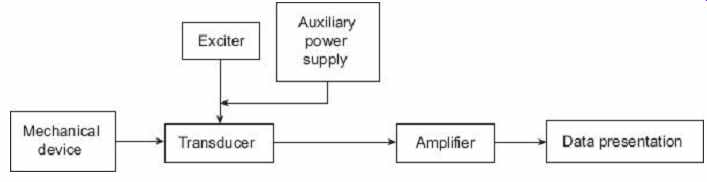
FIG. 8 Electromechanical measurement system
6.6 Deflection and Null Output Instruments
In a deflection-type instrument, the deflection of the instrument indicates the measurement of the unknown quantity. The measurand quantity produces some physical effect which deflects or produces a mechanical displacement in the moving system of the instrument.
An opposite effect is built in the instrument which opposes the deflection or the mechanical displacement of the moving system. The balance is achieved when opposing effect equals the actuating cause producing the deflection or the mechanical displacement.
The deflection or the mechanical displacement at this point gives the value of the unknown input quantity. These type of instruments are suited for measurement under dynamic condition. Permanent Magnet Moving Coil (PMMC), Moving Iron (MI), etc., type instruments are examples of this category.
In null-type instruments, a zero or null indication leads to determination of the magnitude of the measurand quantity. The null condition depends upon some other known conditions. These are more accurate and highly sensitive as compared to deflection-type instruments. A dc potentiometer is a null- type instrument.
7. DEFINITIONS OF SOME STATIC CHARACTERISTICS
1. Accuracy
Accuracy is the closeness with which the instrument reading approaches the true value of the variable under measurement. Accuracy is determined as the maximum amount by which the result differs from the true value. It is almost impossible to determine experimentally the true value. The true value is not indicated by any measurement system due to the loading effect, lags and mechanical problems (e.g., wear, hysteresis, noise, etc.).
Accuracy of the measured signal depends upon the following factors:
• Intrinsic accuracy of the instrument itself;
• Accuracy of the observer;
• Variation of the signal to be measured; and
• Whether or not the quantity is being truly impressed upon the instrument.
2. Precision
Precision is a measure of the reproducibility of the measurements, i.e., precision is a measure of the degree to which successive measurements differ from one another.
Precision is indicated from the number of significant figures in which it is expressed.
Significant figures actually convey the information regarding the magnitude and the measurement precision of a quantity. More significant figures imply greater precision of the measurement.
3. Resolution
If the input is slowly increased from some arbitrary value it will be noticed that the output does not change at all until the increment exceeds a certain value called the resolution or discrimination of the instrument. Thus, the resolution or discrimination of any instrument is the smallest change in the input signal (quantity under measurement) which can be detected by the instrument. It may be expressed as an accrual value or as a fraction or percentage of the full scale value. Resolution is sometimes referred as sensitivity . The largest change of input quantity for which there is no output of the instrument is called the dead zone of that instrument.
The sensitivity gives the relation between the input signal to an instrument or a part of the instrument system and the output. Thus, the sensitivity is defined as the ratio of output signal or response of the instrument to a change of input signal or the quantity under measurement.
Example 1
A moving coil ammeter has a uniform scale with 50 divisions and gives a full-scale reading of 5 A. The instrument can read up to V th of a scale division with a fair degree of certainty. Determine the resolution of the instrument in mA.
Solution
Full-scale reading = 5 A Number of divisions on scale = 50
4. Speed of Response
The quickness of an instrument to read the measurand variable is called the speed of response. Alternately, speed of response is defined as the time elapsed between the start of the measurement to the reading taken. This time depends upon the mechanical moving system, friction, etc.
8. MEASUREMENT OF ERRORS
In practice, it is impossible to measure the exact value of the measurand. There is always some difference between the measured value and the absolute or true value of the unknown quantity (measurand), which may be very small or may be large. The difference between the true or exact value and the measured value of the unknown quantity is known as the absolute error of the measurement.
If δA be the absolute error of the measurement, A m and A be the measured and absolute value of the unknown equantity then δA may be expressed as Sometimes, δA is denoted by ε 0.
The relative error is the ratio of absolute error to the true value of the unknown quantity to be measured, When the absolute error ε 0 (=δA) is negligible, i.e., when the difference between the true value A and the measured value A m of the unknown quantity is very small or negligible then the relative error may be expressed as, The relative error is generally expressed as a fraction, i.e., 5 parts in 1000 or in percentage value, The measured value of the unknown quantity may be more than or less than the true value of the measurand. So the manufacturers have to specify the deviations from the specified value of a particular quantity in order to enable the purchaser to make proper selection according to his requirements. The limits of these deviations from specified values are defined as limiting or guarantee errors. The magnitude of a given quantity having a specified magnitude A m and a maximum or a limiting error ±δA must have a magnitude between the limits
For example, the measured value of a resistance of 100 Ω has a limiting error of ±0.5 Ω.
Then the true value of the resistance is between the limits 100 ± 0.5, i.e., 100.5 and 99.5Ω.
Example 2
A 0-25 A ammeter has a guaranteed accuracy of 1 percent of full scale reading. The current measured by this instrument is 10 A. Determine the limiting error in percentage.
Solution The magnitude of limiting error of the instrument from Eq. (1),
δA = ε r × A = 0.01 × 25 = 0.25 A
The magnitude of the current being measured is 10 A. The relative error at this current is Therefore, the current being measured is between the limit of
A = A m (1 ± ε r ) = 10(1 ± 0.025) = 10 ± 0.25 A
Example 3
The inductance of an inductor is specified as 20 H ± 5 percent by a manufacturer. Determine the limits of inductance between which it is guaranteed.
Solution
Limiting value of inductance, A = A m ± δA
= A m ± ε r A m = A m (1±ε r )
= 20(1 ± 0.05) = 20 ± 1 H
Example 4
A 0-250 V voltmeter has a guaranteed accuracy of 2% of full-scale reading. The voltage measured by the voltmeter is 150 volts. Determine the limiting error in percentage.
Solution The magnitude of the limiting error of the instrument,
δA = ε r V = 0.02 x 250 = 5.0 V
The magnitude of the voltage being measured is 150 V.
The percentage limiting error at this voltage
Example 5
The measurand value of a resistance is 10.25 Ω, whereas its value is 10.22 Ω. Determine the absolute error of the measurement.
Solution
Measurand value A m = 10.25 Ω True value A m = 10.22 Ω Absolute error, δA = A m - A = 10.25 - 10.22 = 0.03 Ω
Example 6 The measured value of a capacitor is 205.3 uF, whereas its true value is 201.4 uF. Determine the relative error.
Solution
Measured value A m = 205.3 × 10^-6 F
True value, A = 201.4 × 10 -6 F
Absolute error, ε 0 = A m - A
= 205.3 × 10 -6 - 201.4 × 10 -6
= 3.9 × 10 -6 F
= 3.9 × 10 -6 F
Example 7
A wattmeter reads 25.34 watts. The absolute error in the measurement is -0.11 watt. Determine the true value of power.
Solution
Measured value A m = 25.34 W Absolute error δA = -0.11 W True value A = Measured value - Absolute error
= 25.34 - (-0.11),
= 25.45 W
8.1 Types of Errors
The origination of error may be in a variety of ways. They are categorized in three main types.
• Gross error
• Systematic error
• Random error
1. Gross Error
The errors occur because of mistakes in observed readings, or using instruments and in recording and calculating measurement results. These errors usually occur because of human mistakes and these may be of any magnitude and cannot be subjected to mathematical treatment. One common gross error is frequently committed during improper use of the measuring instrument. Any indicating instrument changes conditions to some extent when connected in a complete circuit so that the reading of measurand quantity is altered by the method used. For example, in Figure (9)(a) and (b), two possible connections of voltage and current coil of a wattmeter are shown.
In FIG. 9 (a), the connection shown is used when the applied voltage is high and current flowing in the circuit is low, while the connection shown in FIG. 9 (b) is used when the applied voltage is low and current flowing in the circuit is high. If these connections of wattmeter are used in opposite order then an error is liable to enter in wattmeter reading. Another example of this type of error is in the use of a well-calibrated voltmeter for measurement of voltage across a resistance of very high value. The same voltmeter, when connected in a low resistance circuit, may give a more dependable reading because of very high resistance of the voltmeter itself. This shows that the voltmeter has a loading effect on the circuit, which alters the original situation during the measurement.
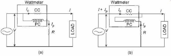
FIG. 9 Different connections of wattmeter
For another example, a multirange instrument has a different scale for each range.
During measurements, the operator may use a scale which does not correspond to the setting of the range selector of the instrument. Gross error may also be there because of improper setting of zero before the measurement and this will affect all the readings taken during measurements. The gross error cannot be treated mathematically, so great care should be taken during measurement to avoid this error. Pictorial illustration of different types of gross error is shown in FIG. 10 .
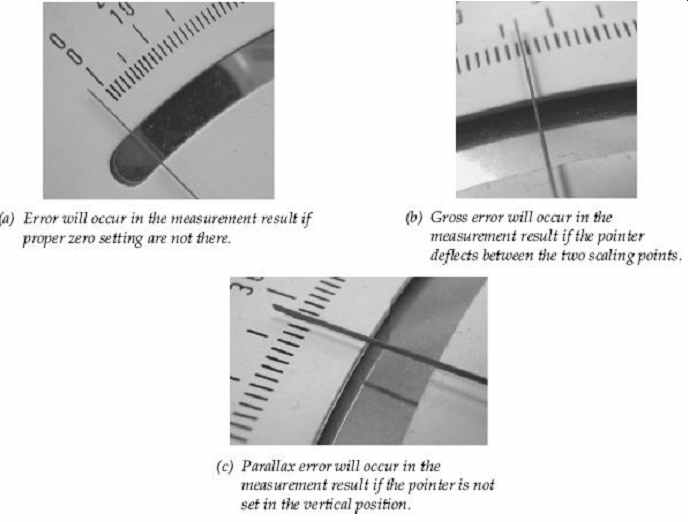
FIG. 10 Different types of gross errors
In general, to avoid gross error, at least two, three or more readings of the measurand quantity should be taken by different observers. Then if the readings differ by an unacceptably large amount, the situation can be investigated and the more erroneous readings eliminated.
2. Systematic Error
These are the errors that remain constant or change according to a definite law on repeated measurement of the given quantity. These errors can be evaluated and their influence on the results of measurement can be eliminated by the introduction of proper correction.
There are two types of systematic errors:
• Instrumental error
• Environmental error
Instrumental errors are inherent in the measuring instruments because of their mechanical structure and calibration or operation of the apparatus used. For example, in D'Arsonval movement, friction in bearings of various components may cause incorrect readings. Improper zero adjustment has a similar effect. Poor construction, irregular spring tensions, variations in the air gap may also cause instrumental errors. Calibration error may also result in the instrument reading either being too low or too high.
Such instrumental errors may be avoided by:
• Selecting a proper measuring device for the particular application
• Calibrating the measuring device or instrument against a standard
• Applying correction factors after determining the magnitude of instrumental errors
Environmental errors are much more troublesome as the errors change with time in an unpredictable manner. These errors are introduced due to using an instrument in different conditions than in which it was assembled and calibrated. Change in temperature is the major cause of such errors as temperature affects the properties of materials in different ways, including dimensions, resistivity, spring effect and many more. Other environmental changes also effect the results given by the instruments such as humidity, altitude, earth's magnetic field, gravity, stray electric and magnetic field, etc. These errors can be eliminated or reduced by taking the following precautions:
• Use the measuring instrument in the same atmospheric conditions in which it was assembled and calibrated.
• If the above precaution is not possible then deviation in local conditions must be determined and suitable compensations are applied in the instrumental reading.
• Automatic compensation, employing sophisticated devices for such deviations, is also possible.
3. Random Errors
These errors are of variable magnitude and sign and do not maintain any known law. The presence of random errors become evident when different results are obtained on repeated measurements of one and the same quantity. The effect of random errors is minimized by measuring the given quantity many times under the same conditions and calculating the arithmetical mean of the results obtained. The mean value can justly be considered as the most probable value of the measured quantity since random errors of equal magnitude but opposite sign are of approximately equal occurrence when making a great number of measurements.
9. LOADING EFFECTS
Under ideal conditions, an element used for signal sensing, conditioning, transmission and detection should not change/distort the original signal. The sensing element should not use any energy or take least energy from the process so as not to change the parameter being measured. However, under practical conditions, it has been observed that the introduction of any element in a system results invariably in extraction of the energy from the system, thereby distorting the original signal. This distortion may take the form of attenuation, waveform distortion, phase shift, etc., and consequently, the ideal measurements become impossible.
The incapability of the system to faithfully measure the input signal in undistorted form is called loading effect. This results in loading error.
The loading effects, in a measurement system, not only occur in the detector-transducer stage but also occur in signal conditioning and signal presentation stages as well. The loading problem is carried right down to the basic elements themselves. The loading effect may occur on account of both electrical and mechanical elements. These are due to impedances of the various elements connected in a system. The mechanical impedances may be treated similar to electrical impedances.
Sometimes loading effect occurs due to the connection of measuring instruments in an improper way. Suppose a voltmeter is connected with parallel of a very high resistance.
Due to the high resistance of the voltmeter itself, the circuit current changes. This is the loading effect of a voltmeter when they are connected in parallel with a very high resistance. Similarly, an ammeter has a very low resistance. So if an ammeter is connected in series with a very low resistance, the total resistance of the circuit changes, and in succession, the circuit current also changes. This is the loading effect of ammeters when they are connected in series with very low resistance.
EXERCISE
Objective-type Questions
1. A null-type instrument as compared to a deflection-type instrument has (a) a lower sensitivity (b) a faster response (c) a higher accuracy (d) all of the above
2. In a measurement system, the function of the signal manipulating element is to (a) change the magnitude of the input signal while retaining its identity (b) change the quantity under measurement to an analogous signal (c) to perform non-linear operation like filtering, chopping and clipping and clamping (d) to perform linear operation like addition and multiplication
3. The measurement of a quantity (a) is an act of comparison of an unknown quantity with a predefined acceptable standard which is accurately known (b) is an act of comparison of an unknown quantity with another quantity (c) is an act of comparison of an unknown quantity with a known quantity whose accuracy may be known or may not be known (d) none of these
4. Purely mechanical instruments cannot be used for dynamic measurements because they have (a) large time constant (b) higher response time (c) high inertia (d) all of the above
5. A modifying input to a measurement system can be defined as an input (a) which changes the input-output relationship for desired as well as interfering inputs (b) which changes the input-output relationship for desired inputs only (c) which changes the input-output relationship for interfering inputs only (d) none of the above
6. In measurement systems, which of the following static characteristics are desirable?
(a) Sensitivity (b) Accuracy (c) Reproducibility (d) All of the above
7. In measurement systems, which of the following are undesirable static characteristics? (a) Reproducibility and nonlinearity (b) Drift, static error and dead zone (c) Sensitivity and accuracy (d) Drift, static error, dead zone and nonlinearity
8. In some temperature measurement, the reading is recorded as 25.70°C. The reading has (a) five significant figures (b) four significant figures (c) three significant figures (d) none of the above
9. In the centre of a zero analog ammeter having a range of -10 A to +10 A, there is a detectable change of the pointer from its zero position on either side of the scale only as the current reaches a value of 1 A (on either side).
The ammeter has a (a) dead zone of 1 A (b) dead zone of 2 A (c) resolution of 1 A (d) sensitivity of 1 A
10. A dc circuit can be represented by an internal voltage source of 50 V with an output resistance of 100 kW. In order to achieve 99% accuracy for voltage measurement across its terminals, the voltage measuring device should have (a) a resistance of at least 10 W (b) a resistance of 100 kW (c) a resistance of at least 10 MW (d) none of the above 11. In ac circuits, the connection of measuring instruments cause loading errors which may affect (a) only the phase of the quantity being measured (b) only the magnitude of the quantity being measured (c) both the phase and the magnitude of the quantity (d) magnitude, phase and also the waveform of the quantity being measured 12. A pressure gauge is calibrated form 0-50 kN/m^2 . It has a uniform scale with 100 scale divisions. One fifth of the scale division can be read with certainty. The gauge has a (a) dead zone of 0.2 kN/m^2
(b) resolution of 0.1 kN/m^2
(c) resolution of 0.5 kN/m^2
(d) threshold of 0.1 kN/m^2
13. A pressure measurement instrument is calibrated between 10 bar and 260 bar. The scale span of the instrument is (a) 10 bar (b) 260 bar (c) 250 bar (d) 270 bar
14. A Wheatstone bridge is balanced with all the four resistances equal to 1 kW each. The bridge supply voltage is 100 V. The value of one of the resistance is changed to 1010 W. The output voltage is measured with a voltage measuring device of infinite resistance. The bridge sensitivity is (a) 2.5 mV/W (b) 10 V/W (c) 25 mV/W (d) none of the above
15. The main advantage of the null balance technique of measurement is that (a) it gives a quick measurement (b) it does not load the medium (c) it gives a centre zero value at its input (d) it is not affected by temperature variation
16. The smallest change in a measured variable to which an instrument will respond is (a) resolution (b) precision (c) sensitivity (d) accuracy
17. The desirable static characteristics of a measurement are (a) precision (b) accuracy (c) sensitivity (d) all of these
18. The errors mainly caused by human mistakes are (a) systematic error (b) instrumental error (c) observational error (d) gross error
19. Systematic errors are (a) environmental error (b) observational error (c) instrumental error (d) all of the above
20. An analog ammeter is (a) an absolute instrument (b) an indicating instrument (c) a controlling instrument (d) a recording instrument
Short-answer Questions
1. Compare the advantages and disadvantages of electrical and mechanical measurement systems.
2. Explain the various classes of measuring instruments with examples.
3. Differentiate clearly between absolute and secondary instruments.
4. Explain analog and digital modes of operation. Why are the digital instruments becoming popular now? What is meant by ADC and DAC?
5. Briefly define and explain all the static characteristics of measuring instruments.
6. Explain loading effect in measurement systems.
7. Explain the terms accuracy, sensitivity and resolution as used for indicating instruments.
8. What are the different types of errors in a measuring instrument? Describe their source briefly.
9. What are fundamental and derived units? Briefly explain them.
10. What are the differences between primary and secondary standards?
Long-answer Questions
1. (a) What is measurement? What is meant by the term measurand? What is a measuring instrument? (b) Write down the important precautions that should be taken while carrying out electrical measurements.
(c) With an example, explain the term loading effect in a measurement system.
2. (a) Explain the terms:
(i) Measurement (ii) Accuracy (iii) Precision (iv) Sensitivity (v) Reproducibility
(b) Define random errors and explain how they are analyzed statistically.
3. (a) What are environmental, instrumental and observational errors? Briefly explain each of them.
(b) Three resistors have the following ratings:
R 1 = 47 W ± 4%, R 2 = 65 W ± 4%, R 3 = 55 W ± 4%
Determine the magnitude and limiting errors in ohms and in percentage of the resistance of these resistors connected in series.
4. (a) What is the necessity of units in measurements? What are various SI units? (b) Define the terms units, absolute units, fundamental units and derived units with suitable examples.
(c) What is systematic error and how can we reduce it?
5. (a) Distinguish between international, primary, secondary and working standards.
(b) What are the primary standards for time and frequency? Briefly discuss each of them.
(c) Describe the working principle, operation and constructional detail of a primary standard of emf.
Prev. | Next