AMAZON multi-meters discounts AMAZON oscilloscope discounts
1. INTRODUCTION
Nowadays everyone is familiar with analog signals. They are used for the movement of an electromagnetic meter to measure voltage, current, resistance, power, etc. Although the bridges and multipliers use electrical components for these measurements, the instruments described use no amplifiers to increase the sensitivity of the measurements. The heart of these instruments was the d'Arsonval meter, which typically cannot be constructed with a full-scale sensitivity of less than about 50 μA. Any measurement system using the d'Arsonval meter, without amplifiers, must obtain at least 50 μA from the circuit under test for a full-scale deflection. For the measurement of currents of less than 50 μA full scale, an amplifier must be employed. The resistance of a sensitive meter, such as a 50 μA meter for a volt-ohm- milliammeter, is of the order of a few hundred ohms and represents a small but finite amount of power. As an example, 50 μA through a 200 Ω meter represents ½ microwatt. This represents the power required for a meter for full-scale deflection and does not represent the power dissipated in the series resistor, and thus the total power required by the example meter would be greater than ½ μW and would depend on the voltage range. This does not sound like much power, but many electronics circuits cannot tolerate this much power being drained from them. So the electronics instruments are required for measuring very small current and voltage.
Electronic instruments, mainly electronic voltmeters, used either transistors or vacuum tubes. The later one is called the Vacuum Tube Voltmeter (VTVM) and the former one is called the Transistorized Voltmeter (TVM). In almost every field of electronics, VTVMs have been replaced by TVMs because of their numerous advantages. In TVM, due to the absence of a heating element, warm-up time is not required. It is portable due to the light weight of the transistor. VTVMs cannot measure current due to the very high resistance whereas due to the low resistance of the TVM, it can measure the current directly from the circuit. VTVMs also cannot measure high-frequency signals. The only disadvantage of TVM over VTVM is that the TVM has very low input impedance. But using FET (Field Effect Transistor) in the input stage of the voltmeter overcomes this low-impedance problem, because an FET offers input impedance almost equal to a vacuum tube.
2. MERITS AND DEMERITS OF DIGITAL INSTRUMENTS OVER ANALOG ONES
Although electronics are usually more costly than electrical instruments but are becoming more and more popular because of their various advantages over conventional ones, some of the main advantages are discussed below:
1. Detection of Low Level Signals
As indicated above analog instruments use PMMC movement for indication. This movement cannot be constructed with a full scale sensitivity of less than 50 mA. Any measurement using a PMMC movement must draw a current of 50 mA from the measured quantity for its operation for full scale deflection if conventional voltmeters are used. This would produce great loading effects especially in electronic and communication circuits. Electronic voltmeter avoids the loading errors by supplying the power required for measurement by using external circuits like amplifiers.
The amplifiers not only supply power for the operation but make it possible for low level signals, which produce a current less than 50 mA for full scale deflection, to be detected which otherwise cannot be detected in the absence of amplifiers. Let us examine the loading effect. A typical meter has a resistance of 200 W and its operating current at full scale is 50 mA. This means the power consumed is only (50 x10^-6 ) 2 x 200 = 0.5 mW. This is extremely a low power for the power circuits but not for many electronic and communication circuits. If this power is taken from the measurand, the signal gets greatly distorted in case power level the circuit is very small and to offset this power is supplied from outside through use of amplifiers.
Let us have a look at the voltage. A meter with 200 W internal resistance and full scale current of 50 mA will have full scale voltage range of 50 x 10^-6 x 200 = 10 mV. Now in case of lower ranges of voltages have to be measured, the use of a voltage amplifier becomes absolutely necessary. This is only possible through use of electronic voltmeters which allow the use of an amplifier. Therefore, it is possible to measure currents below 50 mA, voltages below 10 mV and keep drawn the power drainage below 0.5 mW by using electronic voltmeters through use of amplifiers which is otherwise not possible with conventional types of meter using PMMC movement. For the case of ac measurements, the use of an amplifier for detection of low level signals is even more necessary for sensitive measurements.
2. High Input Impedance
A conventional PMMC voltmeter is a rugged and an accurate instrument, but it suffers from certain disadvantages. The principle problem is that it lacks both high sensitivity and high input resistance. It has a sensitivity of 20 kW/V with a 0 - 0.5 V range and has an input resistance of only 10 kW at its 0.5 V range with the result it has a full scale current of 50 mA which loads the measurand considerably. In electronics and communication circuits even this low value of current may not be tolerable on account of the fact that these circuits have very low operating currents. The electronic voltmeter (EVM), on the other hand, can have input resistances from 10 MW to 100 MW with the input resistance remaining constant over all ranges instead of being different at different ranges, the EVM gives for less loading effects.
3. Low Power Consumption
Electronic voltmeters utilize the amplifying properties of vacuum tubes and transistors and therefore the power required for operating the instrument can be supplied from an auxiliary source. Thus, while the circuit whose voltage is being measured controls the sensing element of the voltmeter, the power drawn from the circuit under measurement is very small or even negligible. This can be interpreted as the voltmeter circuit has very high input impedance. This feature of electronic voltmeter is indispensable for voltage measurement in many high impedance circuits such as encountered in communicating equipments.
4. High Frequency Range
The most important feature of electronic voltmeters is that their response can be made practically independent of frequency within extremely wide limits.
Some electronic voltmeters permit the measurement of voltage from direct current to frequency of the order of hundreds of MHz. the high frequency range may also be attributed to low input capacitance of most electronics devices. The capacitance may be of the order of a few pF.
5. Better Resolution
Resolution (smallest reading perceivable) of analog instruments is limited by space on the scale markings and also by ability of the human operator to read such small deviations in scale markings. Whereas in a digital instrument, the measured value is displayed directly on a LED or LCD panel whose resolution is solely determined by resolution of the analog to digital converter (ADC). Use of 12 bit (or higher) ADC can make a digital instrument to read as small as 0.001 V in 0 - 5 V range.
6. Storage Facility
Digital instruments have an additional optional advantage that their readings can be stored for future reference. Since the value displayed is obtained through an ADC, the digital data can be easily stored in a microprocessor or PC memory. Such storage facility can only be made available in analog instruments by the use of chart recorders where the pointer has a ink source that keeps on marking the values on a roll of moving paper.
7. Accuracy
Since there are very few moving parts (or even no moving parts) in the digital instruments, in general they are usually more accurate than the analog instruments. Even the human error involved in reading these instruments is very less, which adds to the accuracy of digital instruments. However, overall accuracy of a digital instrument will largely depend on accuracies of the large number of individual electronic components used for building the instrument.
In addition, digital instruments are more user friendly as they are easy to read, takes up smaller space, suitable for mass production, and also sometimes less costly.
Disadvantages of Digital Instruments
1. Effects on noise in more predominant on digital instruments than analog instruments.
Analog instruments, due to inertia of its moving parts, normally remain insensitive to fast varying noise, while digital instruments continue to show erratic variations in presence of noise.
2. Analog instruments have higher overload capacity than digital instruments. The sensitive electronic components used in digital instruments are more prone to damage in case of even momentary overloads.
3. Digital instruments can sometimes loose its reliability and tend to indicate erratic values due to faulty electronic circuit components or damaged display.
4. Digital instruments and their internal electronic components are very much sensitive to external atmospheric conditions. In case of high humidity and corrosive atmosphere the internal parts may get damaged and indicate the faulty values.
3. PERFORMANCE CHARACTERISTICS OF DIGITAL METERS
The performance characteristics of digital instruments are resolution, accuracy, linear errors, monotonicity, settling time and temperature sensitivity.
1. Resolution
It is the reciprocal of the number of discrete steps in the Digital to Analog (D/A) converter input. Resolution defines the smallest increment in voltage that can be discerned.
Evidently resolution depends on the number of bits, i.e., the smallest increment in output voltage is determined by the Least Significant Bit (LSB). Percentage resolution is [1/(2 n - 1)] × 100, where N is the number of bits.
2. Accuracy
It is a measure of the difference between actual output and expected output. It is expressed as a percentage of the maximum output voltage. If the maximum output voltage (or full-scale deflection) is 5 volt and accuracy is ±0.1%, then the maximum error is (0.1/100) × 5 = 0.005 volt or 5 mV. Ideally the accuracy should be better than ±½ of LSB. In a 8-bit converter, LSB is 1/255 or 0.39% of full scale. The accuracy should be better than 0.2%.
3. Linear Error
Linearity means that equal increments in digital input of digital instruments should result in equal increment in analog output voltage. If the values of resistances are very accurate and the other components are also ideal, there would be perfectly linear relation between output and input and output-input graph would be a straight line. Because of the fact that resistances used in the circuit have some tolerance, a perfectly linear relation between input and output is not obtained. A special case of linear error is offset error which is the output voltage when digital input is 0000.
4. Monotonicity
A Digital to Analog (D/A) converter is monotonic if it does not take any reverse step when it is sequenced over the entire range of input bits.
5. Settling Time
When the digital input signal changes, it is desirable that analog output signal should immediately show the new output value. However, in actual practice, the D/A converter takes some time to settle at the new position of the output voltage. Settling time is defined as the time taken by the D/A converter to settle within ±½ LSB of its final value when a change in input digital signal occurs. The finite time taken to settle down to new value is due to the transients and oscillations in the output voltage.
6. Temperature Sensitivity
The reference voltage supplied to the resistors of a D/A converter are all temperature sensitive. Therefore, the analog output voltage depends, at least to some extent, on the temperature. The temperature sensitivity of the offset voltage and the bias current of OPAMP also affect the output voltage. The range of temperature sensitivity for a D/A converter is from about ±50 to ±1.5 ppm/°C.
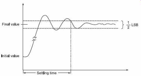
Figure 1 Settling time of a digital instrument
4. DIGITAL MULTIMETER
A digital multimeter is an electronic instrument which can measure very precisely the dc and ac voltage, current (dc and ac), and resistance. All quantities other than dc voltage is first converted into an equivalent dc voltage by some device and then measured with the help of digital voltmeter.
The block diagram of a digital multimeter is shown in Figure 2 . The procedures of measurement of different quantities are described below.
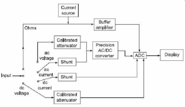
Figure 2 Block diagram of a digital multimeter
For measurement of ac voltage, the input voltage, is fed through a calibrated, compensated attenuator, to a precision full-wave rectifier circuit followed by a ripple reduction filter. The resulting dc is fed to an Analog Digital Converter (ADC) and the subsequent display system. Many manufacturers provide the same attenuator for both ac and dc measurements.
For current measurement, the drop across an internal calibrated shunt is measured directly by the ADC in the 'dc current mode', and after ac to dc conversion in the 'ac current mode'. This drop is often in the range of 200 mV (corresponding to full scale).
Due to the lack of precision in the ac-dc conversions, the accuracy in the ac range is generally of the order of 0.2 to 0.5%. In addition, the measurement range is often limited to about 50 Hz at the lower frequency end due to the ripple in the rectified signal becoming a non-negligible percentage of the display and hence results in fluctuation of the displayed number. At the higher frequency end, deterioration of the performance of the ADC converter limits the accuracy. In ac measurement the reading is often average or rms values of the unknown current. Sometimes for measurement of current, a current-to-voltage converter may also be used, as block diagram in Figure 3 .
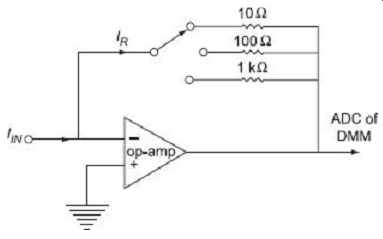
Figure 3 Block diagram of a current-to-voltage
converter
The current under measurement is applied to the summing junction at the input of the op-amp. The current in the feedback resistor I R is equal to the input current I IN because of very high input impedance of the op-amp. The current I R causes a voltage drop across one of the resistors, which is proportional to the input current I IN . Different resistors are employed for different ranges.
For resistance measurement the digital multimeter operates by measuring the voltage across the externally connected resistance, resulting from a current forced through it from a calibrated internal current source. The accuracy of the resistance measurement is of the order of 0.1 to 0.5% depending on the accuracy and stability of the internal current sources. The accuracy may be proper in the highest range which is often about 10 to 20 MΩ. In the lowest range, the full scale may be nearly equal to>200 Ω with a resolution of about 0.01 Ω for a 4½ digit digital multimeter. In this range of resistance measurement, the effect of the load resistance will have to be carefully considered.
=====
Table 1 Comparison between analog and digital multimeter
Analog Multimeter | Digital Multimeter
No external power supply required. An external power supply is required.
Visual indication of change in reading is better observable. Less observable.
Less effect of electronic noise. More affected by electronic noise.
Less isolation problems. More isolation problems.
It has less accuracy. Highly accurate instrument.
Interface of the output with external equipment is not possible.
Possible to connect an external instrument with the output reading.
Simple in construction. Very complicated in construction.
Big in size. Small in size.
Low cost. More costlier instrument.
The output is ambiguous in many times. Unambiguous reading due to digital indication.
=====
5. DIGITAL FREQUENCY METER
A frequency counter is a digital instrument that can measure and display the frequency of any periodic waveform. It operates on the principle of gating the unknown input signal into the counter for a predetermined time. For example, if the unknown input signal were gated into the counter for exactly 1 second, the number of counts allowed into the counter would be precisely the frequency of the input signal. The term gated comes from the fact that an AND or an OR gate is employed for allowing the unknown input signal into the counter to be accumulated.
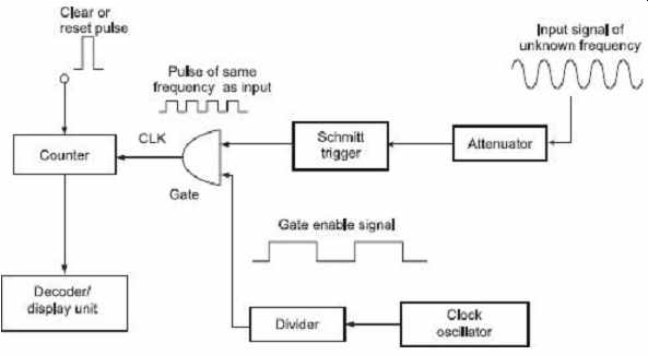
Figure 4 Block diagram of frequency counter
One of the most straightforward methods of constructing a frequency counter is shown in Figure 4 in simplified form. It consist of a counter with its associated display/decoder circuitry, clock oscillator, a divider and an AND gate. The counter is usually made up of cascaded Binary Coded Decimal (BCD) counters and the display/decoder unit converts the BCD outputs into a decimal display for easy monitoring.
A GATE ENABLE signal of known time period is generated with a clock oscillator and a divider circuit and is applied to one leg of an AND gate. The unknown signal is applied to the other leg of the AND gate and acts as the clock for the counter. The counter advances one count for each transition of the unknown signal, and at the end of the known time interval, the contents of the counter will be equal to the number of periods of the unknown input signal that have occurred during time interval, t . In other words, the counter contents will be proportional to the frequency of the unknown input signal. For instance if the gate signal is of a time of exactly 1 second and the unknown input signal is a 600-Hz square wave, at the end of 1 second the counter will counts up to 600, which is exactly the frequency of the unknown input signal.
The waveform in Figure 5 shows that a clear pulse is applied to the counter at t 0 to set the counter at zero. Prior to t 1 , the GATE ENABLE signal is LOW, and so the output of the AND gate will be LOW and the counter will not be counting. The GATE ENABLE goes HIGH from t 1 to t 2 and during this time interval t (= t 2 - t 1 ), the unknown input signal pulses will pass through the AND gate and will be counted by the counter. After t 2 , the AND gate output will be again LOW and the counter will stop counting. Thus, the counter will have counted the number of pulses that occurred during the time interval, t of the GATE ENABLE SIGNAL, and the resulting contents of the counter are a direct measure of the frequency of the input signal.
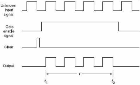
Figure 5 Different waveforms in a frequency counter
The accuracy of the measurement depends almost entirely on the time interval of the GATE ENABLE signal, which needs to be controlled very accurately. A commonly used method for obtaining very accurate GATE ENABLE signal is shown in Figure 6 . A crystal controlled oscillator is employed for generating a very accurate 100 kHz waveform, which is shaped into the square pulses and fed to a series of decade counters that are being used to successively divide this 100 kHz frequency by 10. The frequencies at the outputs of each decade counter are as accurate as the crystal frequency.
The switch is used to select one of the decade counter output frequencies to be supplied to a single Flip-flop to be divided by 2. For instance in switch position 1, the 1 Hz pulses are supplied to flip-flop Q , which acts as a toggle flip-flop so that its output will be a square wave with a period if T = 2 s and a T pulse duration, 1s . In position 2, the pulse duration would be 0.1s, and so on in other positions of the select switch.
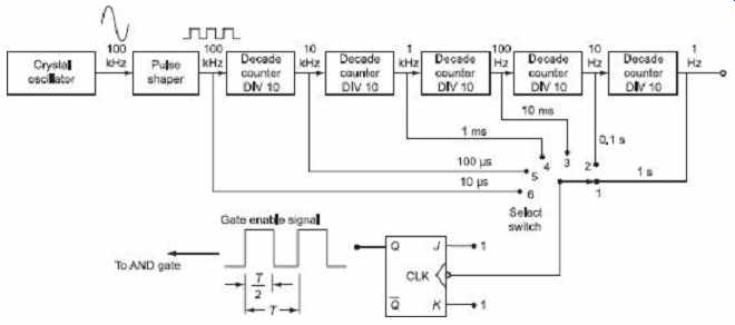
Figure 6 Method of obtaining very accurate GATE
ENABLE signal.
Prev. | Next