AMAZON multi-meters discounts AMAZON oscilloscope discounts
(cont. from part 1)
6. DIGITAL VOLTMETERS (DVMS)
The Digital Voltmeter (DVM) displays measurement of ac or dc voltages as discrete numbers instead of a pointer deflection on a continuous scale as in analog instruments. It is a versatile and accurate instrument that is employed in many laboratory measurement applications. Because of development and perfection of IC modules, their size, power consumptions and cost of the digital voltmeters has been drastically reduced and, therefore, DVMs are widely used for all measurement purposes.
The block diagram of a simple digital voltmeter is shown in Figure 7. The unknown signal is fed to the pulse generator which generates a pulse whose width is directly proportional to the input unknown voltage.
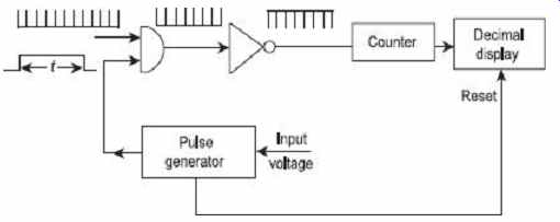
Figure 7 Block diagram of DVM
The output of the pulse generator is applied to one leg of an AND gate. The input signal to the other leg of the AND gate is a train of pulses. The output of the AND gate is, thus, a positive trigger train of duration t second and the inverter converts it into a negative trigger train. The counter counts the number of triggers in t seconds which is proportional to the voltage under measurement. Thus, the counter can be calibrated to indicate voltage in volts directly.
Thus, the DVMs described above is an Analog to Digital Converter (ADC) which converts an analog signal into a train of pulses, the number of which is proportional to the input voltage. So a digital voltmeter can be made by using any one of the analog to digital conversion methods and can be represented by a block diagram shown in Figure 8 . So the DVMs can be classified on the basis of ADCs used.

Figure 8 Representation of DVM using blocks
The input range of the DVM may vary from ±1.00000 V to ±1000.00 V and its limiting accuracy is as high as ±0.005 percent of the reading. Its resolution may be 1 part in 10^6 , giving 1 μV reading of the 1 V input range. It has high input resistance of the order of 10 MΩ and input capacitance of the order of 40 pF.
Digital voltmeters employing different analog to digital conversion methods are described below:
6.1 Ramp-Type DVM
The operation of a ramp-type DVM is based on the measurement of the time that a linear ramp voltage takes to change from the level of the input voltage to zero voltage or vice-versa.
This time interval is measured with an electronic time interval counter and the count is displayed as a number of digits on the electronic indicating tubes of the voltmeter output readouts.
The operating principle and block diagram of a ramp-type DVM are given in Figures 9(a) and 9(b) respectively.
At the start of measurement, a ramp voltage is initiated, this voltage can be positive going or negative going. In Figure 9 (a), negative going voltage ramp is illustrated.
The ramp voltage is continuously compared with the voltage under measurement (unknown voltage). At the instant the value of ramp voltage becomes equal to the voltage under measurement, a coincidence circuit, called the input comparator , generates a pulse which opens a gate, as shown in Figure 9 (b). The ramp voltage continues to fall till it reaches zero value (or ground value). At this instant another comparator, called the ground comparator , generates a stop pulse. The output pulse from this ground comparator closes the gate. The time duration of the gate opening is proportional to the value of the dc input voltage.
The time elapsed between opening and closing the gate is t , as illustrated in Figure 9 (a). During this time interval pulses from a clock pulse oscillator pass through the gate and are counted and displayed. The decimal number indicated by the readout is a measure of the value of the input voltage.
The sample rate multivibrator determines the rate at which the measurement cycles are initiated. The sample rate circuit provides an initiating pulse for the ramp generator to start its next ramp voltage. At the same time a reset pulse is generated, which resets the counter to zero state.
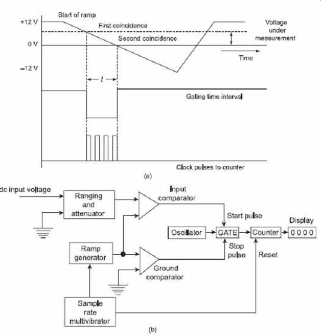
Figure 9 (a) Voltage-to-time conversion (b) Block diagram of a ramp-type DVM
6.2 Dual-Slope Integrating-Type DVM
The block diagram of a dual-slope integrating-type DVM is given in Figure 10 (a). The dual slope ADC consists of five blocks namely an OP-AMP employed as an integrator, a level comparator, a basic clock for generating time pulses, a set of decimal counter and a block of logic circuitry.
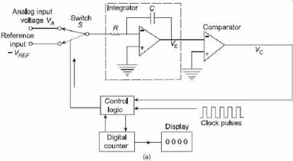
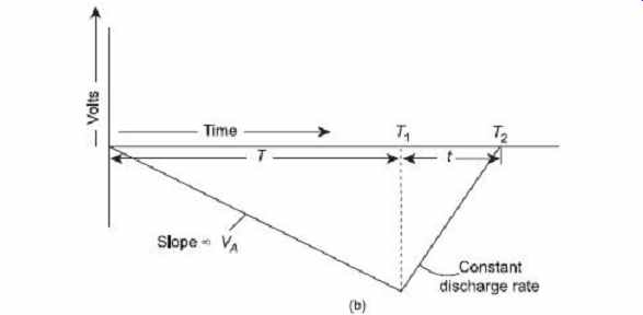
Figure 10 (a) Block diagram of a Dual-Slope Integrating-type
DVM (b) Principle of operation of dual-slope-type DVM
For a fixed time interval (usually, the full count range of the counter), the analog input voltage to be measured, is applied through the switch S to the integrator which raises the voltage in the comparator to some negative value, as illustrated in Figure 10 (b), obviously at the end of fixed time interval the voltage from the integrator will be greater in magnitude for larger input voltage, i.e., rate of increase of voltage or slope is proportional to the analog input voltage. At the end of the fixed count interval, the count is set at zero and the switch S is shifted to the reference voltage V REF of opposite polarity. The integrator output or input to the capacitor then starts increasing at a fixed rate, as illustrated in Figure 10 (b). The counter advances during this time. The integrator output voltage increases at a fixed rate until it rises above the comparator reference voltage, at which the control logic receives a signal (the comparator output) to stop the count. The pulse counted by the counter thus has a direct relation with the input voltage V A .
During charging, the output voltage V 0 is given as Now the capacitor C has already a voltage of (initial voltage), During discharging, the output voltage is given as ...
V 0 = Initial voltage of the capacitor
At t = T 2 (the time measured by the counter), the output voltage of the integrator becomes zero …
Thus, the count shown by the counter ( T 2 ) is proportional to the input voltage to be measured, V A . The display unit displays the measured voltage.
The averaging characteristics and cancellation of errors that usually limit the performance of a ramp-type DVM are the main advantages of dual slope integrating type DVM. The integration characteristics provide the average value of the input signal during the period of first integration. Consequently, disturbances, such as spurious noise pulses, are minimized. Long-term drifts in the time constant as may result from temperature variations or aging, do not affect conversion accuracy. Also, long-term alternations in clock frequency have no effect.
6.3 Integrating-Type DVM (Voltage to Frequency Conversion)
Such a digital voltmeter makes use of an integration technique which employs a voltage to frequency ( V / f ) conversion. This voltmeter indicates the true average value of the unknown voltage over a fixed measuring period.
An analog voltage can be converted into digital form by producing pulses whose frequency is proportional to the analog input voltage. These pulses are counted by a counter for a fixed duration and the reading of the counter will be proportional to the frequency of the pulses, and hence, to the analog voltage.
A block diagram of a voltage to frequency ADC is shown in Figure 11. The analog input voltage V A is applied to an integrator which in turn produces a ramp signal whose slope is proportional to the input voltage. When the output voltage V 0 attains a certain value (a preset threshold level), a trigger pulse is produced and also a current pulse is generated which is used to discharge the integrator capacitor C. Now a new ramp is initiated. The time between successive threshold level crossings is inversely proportional to the slope of the ramp. Since the ramp slope is proportional to the input analog voltage V A , the frequency of the output pulses from the comparator is, therefore, directly proportional to the input analog voltage. This output frequency may be measured with the help of a digital frequency counter.
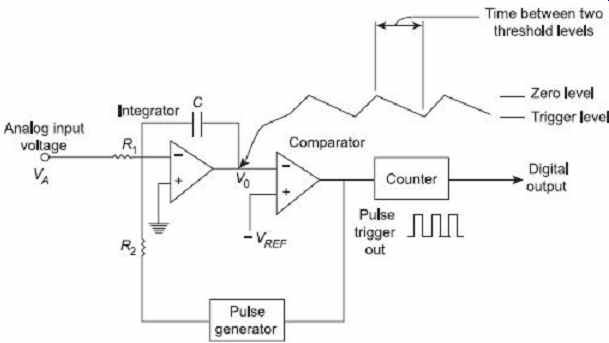
Figure 11 Block diagram of an integrating-type
DVM
The above method provides measurement of the true average of the input signal over the ramp duration, and so provides high discrimination against noise present at the input.
However, the digitizing rates are slow because of high integration durations. The accuracy of this method is comparable with the ramp type ADC, and is limited by the stability of the integrator time constant, and the stability and accuracy of the comparator.
This DVM has the drawback that it needs excellent characteristics in the linearity of the ramp. The ac noise and supply noise are averaged out.
6.4 Applications of DVMs
DVMs are often used in 'data processing systems' or 'data logging systems'. In such systems, a number of analog input signals are scanned sequentially by an electronic system and then each signal is converted to an equivalent digital value by the A/D converter in the DVM.
The digital value is then transmitted to a pointer along with the information about the input line from which the signal has been derived. The whole data is then printed out.
In this way, a large number of input signals can be automatically scanned or processed and their values either printed or logged.
7. SIGNAL GENERATORS
A signal generator is numerously known as test signal generator, tone generator, arbitrary waveform generator, frequency generator, digital pattern generator, function generator, etc. It is an electronic device which produces repeating or non-repeating electronic signals (either analog or in digital patterns). These signals are utilized in testing, designing, troubleshooting and repairing electronic devices; apart from their artistic uses as well. Signal generators also modulate sinusoidal output signal with other signals. This feature is the main distinguisher between the signal generator and oscillator. When an unmodulated sinusoidal output is generated by the signal generators then they are said to be producing CW (continuous height wave) signal. When they produce modulated output signals then they can be in the form of square waves, externally applied sine waves, pulses, triangular waves, or more complex signals, as well as internally generated sine waves. Although Amplitude Modulation (AM) or Frequency Modulation (FM) can be used, yet amplitude modulation is generally employed. In Figures 12(a) and 12(b) , the principles of amplitude modulation and frequency modulation are shown respectively.
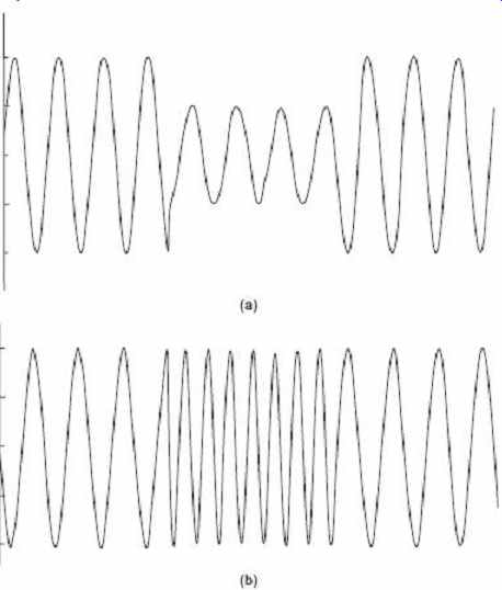
Figure 12 (a) Amplitude modulation (b) Frequency modulation
For providing appropriate signals for calibration and testing, signal generators are mainly employed. They are also used for troubleshooting of the amplifier circuits used in electronic and communications circuit amplifiers. Signal generators also measure the features of antennas and transmission lines.
Figure 13 illustrates the block diagram of a signal generator. A Radio Frequency (RF) oscillator is applied for producing a carrier waveform whose frequency can be attuned typically from about 100 kHz to 40 MHz. With the help of vernier dial setting and range selector switch, carrier wave frequencies can be varied and displayed. Frequency dividers are employed to determine the range. An oscillator s frequency stability is kept very high at all frequency ranges.
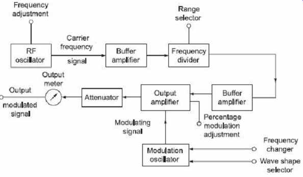
Figure 13 Block diagram of an AM signal generator
The following measures are taken in order to attain stable frequency output.
1. Regulated power supply is employed to reduce the change in supply voltage as it changes frequency of output voltage.
2. To separate the oscillator circuit from output circuit, buffer amplifiers are used. This is done so that any change in the circuit linked to the output does not affect the amplitude and frequency of the oscillator.
3. Temperature compensating devices are used to stable the temperature which causes change in oscillator frequency.
4. In place of an LC oscillator, a quartz crystal oscillator is employed to achieve high Q factor, for instance, 20000.
5. When an audio frequency modulating signal is generated in another very stable oscillator, it is called the modulation oscillator . For changing the amplitude and the frequency of the produced signal, provision is made in the modulation oscillator.
6. Provision is also employed to get several types of waveforms such as the pulses, square, triangular oscillator. The modulation frequency and radio frequency signals are applied to a broadband amplifier, called the output amplifier . Modulation percentage is indicated and adjusted by the meter.
7. A control device can adjust modulation level up to 95%. The amplifier output is then sent to an attenuator and at last the signal reaches the output of the signal generator.
An output meter reads or displays the final output signal.
8. An important specification of the signal generator performance is depending by the accuracy to which the frequency of the RF oscillator is tuned. Most laboratory-type signal generators are generally calibrated to be within 0.5-1.0% of the dial setting.
For most measurements, this accuracy is sufficient. If greater accuracy is required then a crystal oscillator (frequency).
9. Depending upon the different purposes and applications, various types of signal generators are available, however no device is suitable for all possible applications.
Though traditional signal generators have embedded hardware units, with the advancement of multimedia-computers, audio software, tone generators signal generators have become more user-friendly and versatile.
EXERCISE
Objective-type Questions
1. Which one of the following statements is correct? An electronic voltmeter is more reliable as compared to multimeter for measuring voltages across low impedance because (a) its sensitivity is high (b) it offers high input impedance (c) it does not alter the measured voltage (d) its sensitivity and input impedance are high and do not alter the measured value
2. VTVM can be used to measure (a) dc voltage (b) ac voltage of high frequency (c) dc voltage and ac voltage up to the order of 5 MHz frequency (d) ac voltage of low frequency
3. Transistor voltmeter (a cannot measure ac voltage (b) cannot measure high frequency voltage (c) cannot be designed to measure resistance as well as voltage (d) can measure ac voltage
4. An electronic voltmeter provides more accurate readings in high-resistance circuits as compared to a nonelectronic voltmeter because of its (a) low meter resistance (b) high Ω/V ratings (c) high V/Ω ratings (d) high resolution
5. The input impedance of a TVM as compared to that of a VTVM is (a) low (b) high (c) same (d) not comparable
6. The power consumption of a dc voltmeter using a direct coupled amplifier when measuring a voltage of 0.5 volt and having an input impedance of 10 MΩ is (a) a few nanowatts (b) a few milliwatts (c) a few microwatts (d) a few watts
7. FETs are used in the amplifier to get (a) high output impedance (b) high input impedance (c) low output impedance (d) low input impedance
8. A direct voltage is applied to a peak diode voltmeter whose scale is calibrated to read rms voltage of a sine wave.
If the meter reading is 36 V rms, the value of the applied direct voltage is (a) 51 volts (b) 25 volts (c) 36 volts (d) 71 volts
9. A multimeter is used for the measurement of the following:
1. Both ac and dc voltage
2. Both ac and dc current
3. Resistance
4. Frequency
5. Power
Select the correct answer using the codes given:
(a) 1, 2 and 4 (b) 1, 2 and 5 (c) 1, 3 and 5 (d) 1, 2 and 3
10. Modern electronic multimeters measure resistance by (a) using an electronic bridge compensator for nulling (b) forcing a constant current and measuring the voltage across the unknown resistor (c) using a bridge circuit (d) applying a constant voltage and measuring the current through the unknown resistor
11. An n -bit A/D converter is required to convert an analog input in the range of 0-5 volt to an accuracy of 10 mV.
The value of n should be (a) 8 (b) 9 (c) 10 (d) 16
12. Which of the following is not true for a digital frequency counter? (a) less costly (b) high accuracy (c) accepts inputs in the form of train of pulses (d) wide range of frequency measurement
13. The resolution of a 12-bit analog to digital converter in per cent is (a) 0.04882 (b) 0.09760 (c) 0.01220 (d) 0.02441
14. A DVM measures (a) peak value (b) rms value (c) average value (d) peak to peak value
15. Which of the following measurements can be made with the help of a frequency counter?
1. Fundamental frequency of input signal
2. Frequency components of the input signal at least up to third harmonics
3. Time interval between two pulses
4. Pulse width
Select the correct answer using the codes given below:
(a) 2 and 4 (b) 1 and 2 (c) 1, 2 and 3 (d) 1, 3 and 4 16. Accuracy of DVM is specified as (a) percentage of the full scale reading (b) percentage of the actual reading (c) number of least significant digit (d) all of these
Short-answer Questions
1. What are the merits of the digital system over analog system?
2. Briefly describe the performance characteristics of digital measurement.
3. Write down the comparison between analog and digital multimeters.
4. What is the basic principle of digital frequency meter?
5. How many types of digital voltmeters are there? Explain any one of them briefly.
6. What are the applications of the digital voltmeter?
7. How does an electronic voltmeter (EVM) measure ac signal?
Long-answer Questions
1. (a) What are the advantages of digital systems over analog? (b) Explain the following terms as applied to digital measurement.
(i) Resolution (ii) Sensitivity of digital meter (iii) Accuracy specification of digital meters
2. (a) Explain the operating principle of a DVM using a suitable block diagram.
(b) With a neat sketch, describe the operating principle of dual slop integrating type of DVM.
3. Explain with the help of a functional block diagram, the principle of operation of a digital frequency meter.
4. With the help of a functional block diagram, describe the principle of operation of a digital multimeter.
5. What are the advantages of a digital voltmeter over analog type? What are its types? With a block diagram, explain the working of an integrating type. Compare its performance with other types.