AMAZON multi-meters discounts AMAZON oscilloscope discounts
1. INTRODUCTION
An analog device is one in which the output or display is a continuous function of time and bears a constant relation to its input. Measuring instruments are classified according to both the quantity measured by the instrument and the principle of operation. Three general principles of operation are available: (i) electromagnetic, which utilizes the magnetic effects of electric currents; (ii) electrostatic, which utilizes the forces between electrically charged conductors; (iii) electro-thermal, which utilizes the heating effect.
Electric measuring instruments and meters are used to indicate directly the value of current, voltage, power or energy. In this chapter, we will consider an electromechanical meter (input is as an electrical signal which results in mechanical force or torque as an output) that can be connected with additional suitable components in order to act as an ammeter and a voltmeter. The most common analog instrument or meter is the permanent magnet moving coil instrument and it is used for measuring a dc current or voltage of an electric circuit. On the other hand, the indications of alternating current ammeters and voltmeters must represent the rms values of the current, or voltage, respectively, applied to the instrument.
2. CLASSIFICATION OF ANALOG INSTRUMENTS
In a broad sense, analog instruments may be classified into two ways:
1. Absolute instruments
2. Secondary instruments
Absolute instruments give the value of the electrical quantity to be measured in terms of the constants of the instruments and to its deflection, no comparison with another instrument being required. For example, the tangent galvanometer gives the value of the current to be measured in terms of the tangent of the angle of deflection produced by the current, the radius and the number of turns of galvanometer coil, and the horizontal component of the earth's magnetic field. No calibration of the instrument is thus necessary.
Secondary instruments are so constructed that the value of current, voltage or other quantity to be measured can be determined from the deflection of the instruments, only if the latter has been calibrated by comparison with either an absolute instrument or one which has already been calibrated. The deflection obtained is meaningless until such a calibration has been made.
This class of instruments is in most general use, absolute instrument being seldom used except in standard laboratories and similar institutions.
The secondary instruments may be classifies as:
1. Indicating instruments
2. Recording instruments
3. Integrating instruments
Indicating instruments are instruments which indicate the magnitude of a quantity being measured. They generally make use of a dial and a pointer for this purpose.
Recording instruments give a continuous record of the quantity being measured over a specified period. The variation of the quantity being measured are recorded by a pen (attached to the moving system of the instrument; the moving system is operated by the quantity being measured) on a sheet of paper that moves perpendicular to the movement of the pen.
Integrating instruments record totalized events over a specified period of time. The summation, which they give, is the product of time and an electrical quantity. Ampere hour and watt hour (energy) meters are examples of this category.
3. PRINCIPLE OF OPERATION
Analog instruments may be classified according to the principle of operation they utilize.
The effects they utilize are
1. Magnetic effect
2. Heating effect
3. Electrostatic effect
4. Electromagnetic effect
5. Hall effect
The majority of analog instruments including moving coil, moving iron and electrodynamic utilize the magnetic effect. The effect of the heat produced by a current in a conductor is used in thermocouple and hotwire instruments. Electrostatic effect is used in electrostatic voltmeters. The electromagnetic induction effect is used in induction wattmeters and induction energy meters.
4. OPERATING TORQUES
Three types of torques are needed for satisfactory operation of any indicating instrument.
These are:
• Deflecting torque
• Controlling torque
• Damping torque
4.1 Deflecting Torque/Force
Any instrument's deflection is found by the total effect of the deflecting torque/force, control torque/ force and damping torque/force. The deflecting torque's value is dependent upon the electrical signal to be measured; this torque/force helps in rotating the instrument movement from its zero position. The system producing the deflecting torque is called the deflecting system.
4.2 Controlling Torque/Force
The act of this torque/force is opposite to the deflecting torque/force. When the deflecting and controlling torques are equal in magnitude then the movement will be in definite position or in equilibrium. Spiral springs or gravity is usually given to produce the controlling torque. The system which produces the controlling torque is called the controlling system. The functions of the controlling system are:
• To produce a torque equal and opposite to the deflecting torque at the final steady position of the pointer in order to make the deflection of the pointer definite for a particular magnitude of current
• To bring the moving system back to its zero position when the force causing the instrument moving system to deflect is removed The controlling torque in indicating instruments is almost always obtained by a spring, much less commonly, by gravity.
4.3 Damping Torque/Force
A damping force generally works in an opposite direction to the movement of the moving system. This opposite movement of the damping force, without any oscillation or very small oscillation brings the moving system to rest at the final deflected position quickly.
Air friction, fluid friction and eddy currents provide the damping torque/force to act. It must also be noted that not all damping force affects the steady-state deflection caused by a given deflecting force or torque. With the angular velocity of the moving system, the intensity of the damping force rises; therefore, its effect is greatest when it rotates rapidly and zero when the system rotation is zero. In the description of various types of instruments, detailed mathematical expressions for the damping torques are taken into consideration.
When the deflecting torque is much greater than the controlling torque, the system is called underdamped. If the deflecting torque is equal to the controlling torque, it is called critically damped. When deflecting torque is much less than the controlling torque, the system is under overdamped condition. FIG. 1 shows the variation of deflection (d ) with time for underdamped, critically damped and overdamped systems.
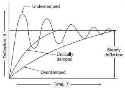
FIG. 1 Damping torque curve
5. CONSTRUCTIONAL DETAILS
5.1 Moving System The moving system should have the following properties:
• The moving parts should be light.
• The frictional force should be minimum.
These requirements should be fulfilled in order that power required by the instrument for its operation is small. The power is proportional to the weight of the moving parts and the frictional forces opposing the movement. The moving system can be made light by using aluminum as far as possible. The frictional forces are reduced by using spindle mounted jewel bearings and by carefully balancing the system.
The force or torque developed by the moving element of an electrical instrument is necessarily small in order that the power consumption of the instrument is kept low so that the introduction of the instrument into a circuit may cause minimum change in the existing circuit conditions. Because of low power levels, the considerations of various methods of supporting the moving elements becomes of vital importance. With the operating force being small, the frictional force must be kept to a minimum in order that the instrument reads correctly and is not erratic in action and is reliable. Supports may be of the following types:
• Suspension
• Taut suspension
• Pivot and jewel bearings
1. Suspension
It consist of a fine, ribbon-shaped metal filament for the upper suspension and a coil of fine wire for the lower part. The ribbon is made of a spring material like beryllium copper or phosphor bronze. This coiling of lower part of suspension is done in order to give negligible restrain on the moving system. The type of suspension requires careful leveling of the instrument, so that the moving system hangs in correct vertical position. This construction is, therefore, not suited to field use and is employed only in those laboratory applications in which very great sensitivity is required. In order to prevent shocks to the suspension during transit, etc., a clamping arrangement is employed for supporting the moving system.
2. Taut Suspension
A suspension type of instrument can only be used in vertical position. The taut suspension has a flat ribbon suspension both above and below the moving element, with suspension kept under tension by a spring arrangement (FIG. 2). The advantage of this type of suspension is that exact leveling is not required if the moving system is properly balanced.
Suspension and taut suspension are customarily used in instruments of galvanometer class which requires a low friction and high sensitivity mechanism. But actually there is no strict line of demarcation between a galvanometer and other indicating instruments.
Some sensitive wattmeters and electrostatic voltmeters use flexible suspension.
Ribbon suspension, in addition to supporting the moving element, exerts a controlling torque when twisted. Thus, the use of suspension results in elimination of pivots, jewels, control springs and therefore, pivotless instruments are free from many defects.
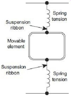
FIG. 2 Taut suspension
3. Pivot and Jewel Bearings
The moving system is mounted on a spindle made of hardened steel. The two ends of the spindle are made conical and then polished to form pivots. These ends fit conical holes in jewels located in the fixed part of instruments (FIG. 3). These jewels, which are preferably made of sapphire, form bearings.
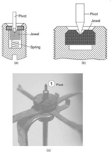
FIG. 3 (a) Spring-loaded jewel bearing (b) Jewel bearing (c) Pivot
It has been found that the frictional torque, for jewel bearings, is proportional to the area of contact between the pivot and jewel. Thus, the contact area between a pivot and jewel should be small. The pivot is ground to a cone and its tip is rounded to a hemispherical surface of small area. The jewel is ground to a cone of somewhat larger angle.
4. Torque/Weight Ratio
The frictional torque in an instrument depends upon the weight of moving parts. If the weight of the moving parts is large, the frictional torque will be large. The frictional torque exerts a considerable influence on the performance of an indicating instrument. If the frictional torque is large and is comparable to a considerable fraction of the deflecting torque, the deflection of the moving system will depend upon the frictional torque to an appreciable extent. Also, the deflection will depend on the direction from which the equilibrium position is approached and will be uncertain. On the other hand, if the frictional torque is very small compared with the deflecting torque, its effect on deflection is negligible. Thus, the ratio of deflecting torque to frictional torque is a measure of reliability of the instrument indications and is the inherent quality of the design. Hence (deflecting) torque/weight ratio of an instrument is an index of its performance. The higher the ratio, the better will be its performance.
The controlling torque is provided by a spring or sometimes by gravity.
1. Spring Control
A hair-spring, usually of phosphor-bronze attached to the moving system, is used in indicating instruments for control purpose, the schematic arrangement being shown in FIG. 4(a) and the actual controlling spring used in the instrument is shown in FIG. 4(b).
To give a controlling torque which is directly proportional to the angle of deflection of the moving system, the number of turns on the spring should be fairly large, so that the deflection per unit length is small. The stress in the spring must be limited to such a value that there is no permanent set.
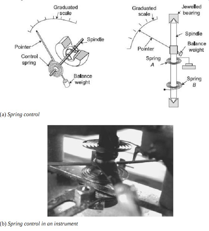
FIG. 4(a) Spring control
FIG. 4(b) Spring control in an instrument
Suppose that a spiral spring is made up of a total length L m of strip whose cross section is rectangular, the radial thickness being t m and the depth b m. Let E be Young's modulus (N/m^2) for the material of the spring. Then, if theta radians be the deflection of the moving system to which one end of the spring is being attached, the expression for the controlling torque is
Thus, controlling torque infinity theta infinity instrument deflection.
2. Gravity Control
In a gravity-controlled instrument, a small weight is attached to the moving system in such a way that it produces a restoring or controlling torque when the system is deflected. This is illustrated in FIG. 5. The controlling torque, when the deflection is ?, is ?l sin ?, where W is the control weight and l its distance from the axis of rotation of the moving system, and it is, therefore, proportional only to the sine of the angle of deflection, instead of, as with spring control, being directly proportional to the angle of deflection. Gravity controlled instruments must obviously be used in a vertical position in order that the control may operate.
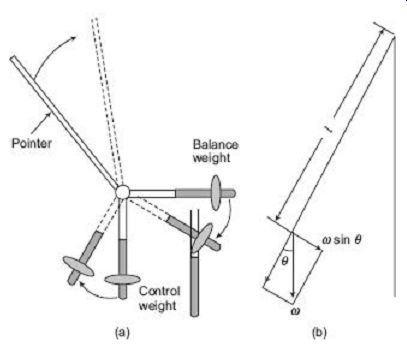
FIG. 5 Gravity control
3. Comparison of Spring and Gravity Control
Gravity control has the following advantages when compared with spring control:
• It is cheaper
• Independent of temperature
• Does not deteriorate with time
Consider an instrument in which the deflecting torque TD is directly proportional to the current (say) to be measured.
Thus, if I is the current,
If the instrument is spring-controlled, the controlling torque being TC, when the deflection is ?,
TC = ks? ( ks is spring constant)
Also, TC = TD or ks? = kI
Thus, the deflection is proportional to the current throughout the scale.
Now if the same instrument is gravity controlled,
TC = kg sin ? (kg is a constant that depends upon the control weight and its distance from the axis of rotation of the moving system).
And TC = TD = kI
Thus, a gravity-controlled instrument would have a scale which is 'cramped' at its lower end instead of being uniformly divided, though the deflecting torque is directly proportional to the quantity to be measured.
5.3 Damping System
There are three systems of damping generally used. These are as follows:
• Air-friction damping
• Fluid-friction damping
• Eddy-current damping
1. Air-Friction Damping
In this method, a light aluminum piston is attached to the moving system and moves in an air chamber closed at one end, as shown in FIG. 6. The cross-section of this chamber may be either circular or rectangular. The clearance between the piston and the sides of the chamber should be small and uniform. If the piston is moving rapidly into the chamber, the air in the closed space is compressed and the pressure opposes the motion of the piston (and, therefore, of the whole moving system). If the piston is moving out of the chamber rapidly, the pressure in the closed space falls, and the pressure on the open side of the piston is greater than that on the opposite side. Motion is thus again opposed. Sometimes instead of a piston, a vane, mounted on the spindle of the moving system, moves in a closed-sector-shaped box as shown in FIG. 7.
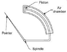
FIG. 6 Open-end air friction damping
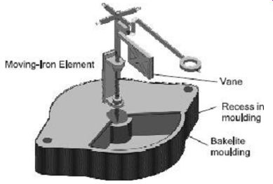
FIG. 7 Air-friction damping using vane
2. Fluid-Friction Damping
In this type of damping, a light vane, attached to the spindle of the moving system, dips into a pot of damping oil and should be completely submerged by the oil. This is illustrated in FIG. 8(a). The frictional drag in the disc is always in the direction opposing motion. There is no friction force when the disc is stationary. In the second system [FIG. 8(b)], increased damping is obtained by the use of vanes.
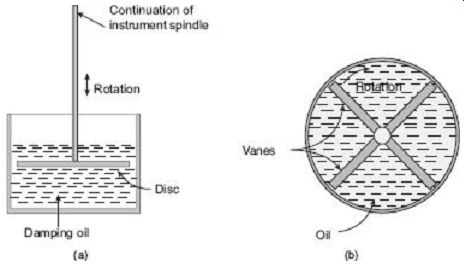
FIG. 8 Fluid-friction damping
3. Eddy-Current Damping
When a sheet of conducting material moves in a magnetic field so as to cut through lines of force, eddy currents are set up in it and a force exists between these currents and the magnetic field, which is always in the direction opposing the motion. The force is proportional to the magnitude of the current and to the strength of the field. The magnitude of the current is proportional to the velocity of movement of the conductor, and thus, if the magnetic field is constant, the damping force is proportional to the velocity of the moving system and is zero when there is no movement of the system.
(i) Eddy-Current Damping Torque of Metal Former
FIG. 9 shows a metallic former moving in the field of a permanent magnet.
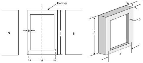
FIG. 9 Eddy-current damping on a metal former
Let,
B = strength of magnetic field; (wb/m^2)
? = angular speed of former; (rad/s)
l = length of former; (m)
t = thickness of former; (m)
b = width of former; (m)
d = breadth of former; (m)
? = resistivity of material of former; (W m)
[since linear velocity = radius × angular velocity]
Dynamically generated emf in the former
(ii) Eddy-Current Damping Torque of Metal Disc
FIG. 10 shows a metallic disc rotating in the field of a permanent magnet.
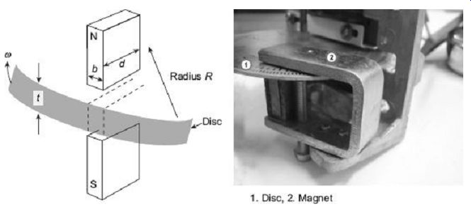
FIG. 10 Eddy-current damping on metallic disc 2
Let, B = flux density of magnetic field; (wb/m^2 )
? = angular speed of disc; (rad/s)
t = thickness of disc; (m)
b = width of permanent magnet; (m)
d = length of permanent magnet; (m)
? = resistivity of material of disc; (O m)
R = radius measured from centre of pole to centre of disc; (m)
Considering the emf is induced in the disc under the pole face only, therefore, emf induces in the portion below the magnet
[since 'l', length of the portion of the disc under the magnetic field = d ]
Actual path for eddy current is not limited to the portion of the disc under the magnet but is greater than this. Therefore, to take this factor into account, the actual resistance is taken as k times of .
where k is a constant which depends upon radial position of the disc and poles.
6. PERMANENT MAGNET MOVING COIL INSTRUMENT
Basic range: 10 µA-100 mA
Coil resistance: 10 Ohm-1 kOhm
Usage:
- dc PMMC ammeters and voltmeters
- ac PMMC ammeters and voltmeters (with rectifiers)
6.1 Principle of Operation
The principle on which a Permanent Magnet Moving Coil (PMMC) instrument operates is that a torque is exerted on a current-carrying coil placed in the field of a permanent magnet. A PMMC instrument is shown in FIG. 11. The coil C has a number of turns of thin insulated wires wound on a rectangular aluminum former F. The frame is carried on a spindle S mounted in jewel bearings J1, J2. A pointer PR is attached to the spindle so that it moves over a calibrated scale. The whole of the moving system is made as light in weight as possible to keep the friction at the bearing to a minimum.
The coil is free to rotate in air gaps formed between the shaped soft-iron pole piece (pp) of a permanent magnet PM and a fixed soft-iron cylindrical core IC [FIG. 11(b)]. The core serves two purposes; (a) it intensifies the magnetic field by reducing the length of the air gap, and (b) it makes the field radial and uniform in the air gap.
Thus, the coil always moves at right angles to the magnetic field [FIG. 11(c)]. Modern permanent magnets are made of steel alloys which are difficult to machine. Soft-iron pole pieces (pp) are attached to the permanent magnet PM for easy machining in order to adjust the length of the air gap. FIG. 11(d) shows the internal parts and FIG. 11(e) shows schematic of internal parts of a moving-coil instrument.
A soft-iron yoke (Y ) is used to complete the flux path and to provide shielding from stray external fields.
Permanent magnet moving coil instrument Photograph of different components of a PMMC instrument Internal construction of PMMC instruments FIG. 11
6.2 Deflecting Torque Equation of PMMC Instrument
Let, B = flux density in the air gap (wb/m^2)
i = current in the coil
(A) l = effective axial length of the coil
(m) b = breadth of the coil
(m) n = number of turns of the coil.
Force on one side of the coil is Torque on each side of the coil,
Total deflecting torque exerted on the coil,
For a permanent magnet, B is constant. Also, for a given coil l, b and n are constants and thus the product (Blnb) is also a constant, say k1.
1. Control Torque
The control on the movement of the pointer over the scale is provided by two spirally wound, phosphor-bronze springs S1 and S2, one at each end of the spindle S. Sometimes these springs also conduct the current into and out of the coil. The control torque of the springs is proportional to the angle ? turned through by the coil.
…where TC is the control torque and ks is the spring constant.
At final steady state position,
Control torque = Deflecting torque
So, angular deflection of the pointer is directly proportional to the current. Thus the scale of the instrument is linear or uniformly divided.
2. Damping Torque
When the aluminum former (F) moves with the coil in the field of the permanent magnet, a voltage is induced, causing eddy current to flow in it. These current exerts a force on the former. By Lenz's law, this force opposes the motion producing it. Thus, a damping torque is obtained. Such a damping is called eddy-current damping.
The coil of the instrument is made of copper. Its resistance varies with temperature. A resistor of low temperature coefficients, called the swamping resistor, is connected in series with the coil. Its resistance practically remains constant with temperature. Hence the effect of temperature on coil resistance is swamped by this resistor.
Advantages of PMMC Instruments
1. Sensitive to small current
2. Very accurate and reliable
3. Uniform scale up to 270° or more
4. Very effective built in damping
5. Low power consumption, varies from 25 µW to 200 µW
6. Free from hysteresis and not effected by external fields because its permanent magnet shields the coil from external magnetic fields
7. Easily adopted as a multirange instrument
Disadvantages of PMMC Instruments
1. This type of instrument can be operated in direct current only. In alternating current, the instrument does not operate because in the positive half, the pointer experiences a force in one direction and in the negative half the pointer experiences the force in the opposite direction. Due to the inertia of the pointer, it retains it's zero position.
2. The moving system is very delicate and can easily be damaged by rough handling.
3. The coil being very fine, cannot withstand prolonged overloading.
4. It is costlier.
5. The ageing of the instrument (permanent magnet and control spring) may introduce some errors.
7. EXTENSION OF RANGE OF PMMC INSTRUMENTS
7.1 Ammeter Shunts
The moving-coil instrument has a coil wound with very fine wire. It can carry only few mA safely to give full-scale deflection. For measuring higher current, a low resistance is connected in parallel to the instrument to bypass the major part of the current. The low resistance connected in parallel with the coil is called a shunt. FIG. 12 shows a shunt resistance Rsh connected in parallel with the basic meter.
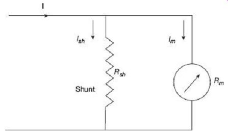
FIG. 12 Extension of PMMC ammeter using shunt
The resistance of the shunt can be calculated using conventional circuit analysis.
Rsh = shunt resistance (?) Rm = coil resistance (?)
Im = Ifs = full-scale deflection current (A)
1sh = shunt current (A)
I = current to be measured (A)
The voltage drop across the shunt and the meter must be same as they are connected in parallel.
From Eq. (25),
The ratio of the total current to the current in the meter is called multiplying power of shunt. Multiplying power, 2.7.2 Voltmeter Multipliers For measuring higher voltages, a high resistance is connected in series with the instrument to limit the current in the coil to a safe value. This value of current should never exceed the current required to produce the full scale deflection. The high resistance connected in series with the instrument is called a multiplier. In FIG. 13, Rsc is the multiplier.
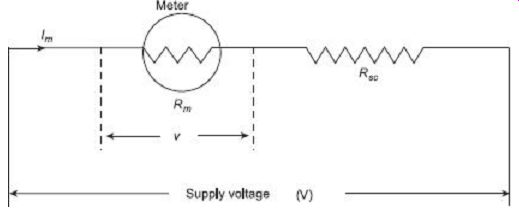
FIG. 13 Extension of PMMC voltmeter using multiplier
The value of multiplier required to extend the voltage range, is calculated as under:
Rsc = multiplier resistance (?)
Rm = meter resistance (?)
Im = Ifs = full scale deflection current (A)
v = voltage across the meter for producing current Im (A)
V = voltage to be measured (A)
V = I mRm
V = Im(Rm + Rsc)
Now multiplying factor for multiplier
Sensitivity
The moving-coil instrument is a very sensitive instrument. It is, therefore, widely used for measuring current and voltage. The coil of the instrument may require a small amount of current (in the range of µA) for full-scale deflection. The sensitivity is sometimes expressed in ohm/volt. The sensitivity of a voltmeter is given by where Ifs is the full-scale deflecting current. Thus, the sensitivity depends upon on the current to give full-scale deflection.
8. MOVING-IRON INSTRUMENTS
Basic range: 10 mA-100 A Usage:
• dc MI ammeters and voltmeters
• ac MI ammeters and voltmeters
Moving-Iron or MI instruments can be classified as:
• Attraction-type moving-iron instruments
• Repulsion-type moving-iron instruments
The current to be measured, in general, is passed through a coil of wire in the moving iron instruments. In case of voltage measurement, the current which is proportional to the voltage is measured. The number of turns of the coil depends upon the current to be passed through it. For operation of the instrument, a certain number of ampere turns is required. These ampere turns can be produced by the product of few turns and large current or reverse.
8.1 Attraction-type Moving-Iron Instruments
The attraction type of MI instrument depends on the attraction of an iron vane into a coil carrying current to be measured. FIG. 14 shows a attraction-type MI instrument. A soft iron vane IV is attached to the moving system. When the current to be measured is passed through the coil C, a magnetic field is produced. This field attracts the eccentrically mounted vane on the spindle towards it. The spindle is supported at the two ends on a pair of jewel bearings. Thus, the pointer PR, which is attached to the spindle S of the moving system is deflected. The pointer moves over a calibrated scale.
The control torque is provided by two hair springs S1 and S2 in the same way as for a PMMC instrument; but in such instruments springs are not used to carry any current.
Gravity control can also be used for vertically mounted panel type MI meters. The damping torque is provided by the movement of a thin vane V in a closed sector-shaped box B, or simply by a vane attached to the moving system. Eddy current damping can not be used in MI instruments owing to the fact that any permanent magnet that will be required to produce Eddy current damping can distort the otherwise weak operating magnetic field produced by the coil.
If the current in the fixed coil is reversed, the field produced by it also reverses. So the polarity induced on the vane reverses. Thus whatever be the direction of the current in the coil the vane is always be magnetized in such a way that it is attracted into the coil. Hence such instrument can be used for both direct current as well as alternating current.
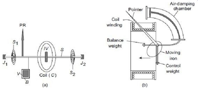
FIG. 14 Attraction-type moving iron (MI) instrument
8.2 Repulsion-type Moving-Iron Instruments
In the repulsion type, there are two vanes inside the coil. One is fixed and the other is movable. These are similarly magnetized when the current flows through the coil and there is a force of repulsion between the two vanes resulting in the movement of the moving vane.
Two different designs for moving iron instruments commonly used are as follows:
1. Radial Vane Type
In this type, the vanes are radial strips of iron. The strips are placed within the coil as shown in FIG. 15(a). The fixed vane is attached to the coil and the movable one to the spindle of the instrument. The instrument pointer is attached to the moving vane spindle.
As current flows through the coil, the generated magnetic field induces identical polarities on both the fixed and moving vane. Thus, even when the current through the coil is alternating (for AC measurement), there is always a repulsion force acting between the like poles of fixed and moving vane. Hence deflection of the pointer is always in the same direction irrespective of the polarity of current in the coil. The amount of deflection depends on the repulsion force between the vanes which in turn depends on the amount of current passing through the coil. The scale can thus be calibrated to read the current or voltage directly.
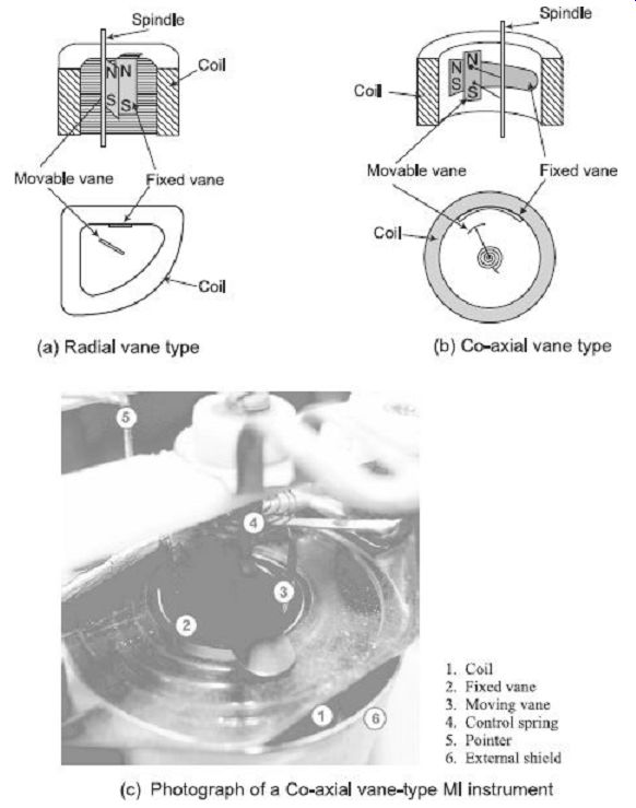
FIG. 15 Repulsion-type Moving Iron (MI) instruments
2. Co-axial Vane Type I
In these type of instruments, the fixed and moving vanes are sections of coaxial cylinders as shown in FIG. 15(b). Current in the coil magnetizes both the vanes with similar polarity. Thus the movable vane rotates along the spindle axis due to this repulsive force. Coaxial vane type instruments are moderately sensitive as compared to radial vane type instruments that are more sensitive.
Moving iron instruments have their deflection is proportional to the square of the current flowing through the coil. These instruments are thus said to follow a square law response and have non-uniform scale marking. Deflection being proportional to square of the current, whatever be the polarity of current in the coil, deflection of a moving iron instrument is in the same direction. Hence, moving iron instruments can be used for both DC and AC measurements.
8.3 Torque Equation of Moving-Iron Instruments
To deduce the expression for torque of a moving iron instrument, energy relation can be considered for a small increment in current supplied to the instrument. This result in a small deflection d? and some mechanical work will be done. Let Td be the deflecting torque.
Therefore mechanical work done = torque × angular displacement Due to the change in inductance there will be a change in the energy stored in the magnetic field.
Let I be the initial current, L be the instrument inductance and ? is the deflection. If the current increases by dl then it causes the change in deflection d? and the inductance by dL.
In order to involve the increment dI in the current, the applied voltage must be increase by:
[substitute the value of edt from equation (28)
The current is changes from I to (I + dI), and the inductor L to (L + dL) Therefore the stored energy changes from As dI and dL are very small, neglecting the second and higher order terms in small quantities, this becomes From the principle of conservation of energy, Electrical energy supplied = Increase in stored energy + Mechanical work done.
Where:
Td is in newton-meter, I is in ampere, L is in henry and ? is in radians.
The moving system is provided with control springs and in turn the deflecting torque Td is balanced by the controlling torque TC = k ? where k is the control spring constant (N-m/rad) and ? is the deflection in radians.
At final steady position, TC = Td
Hence, the deflection is proportional to square of the rms value of the operating current.
The deflection torque is, therefore, unidirectional whatever may be the polarity of the current.
Advantages of MI Instruments
1. Robust construction and relatively cheap
2. Suitable for measuring both dc and ac
3. Can withstand overload momentarily
Disadvantages of MI Instruments
1. As the deflection is proportional to I^2, hence the scale of the instrument is not uniform. It is cramped in the lower end and expanded in the upper portion.
2. It is affected by stray magnetic fields.
3. There is hysteresis error in the instrument. The hysteresis error may be minimized by using the vanes of nickel-iron alloy.
4. When used for measuring ac the reading may be affected by variation of frequency due to the change in reactance of the coil, which has some inductance. With the increase in frequency iron loses and coil impedance increases.
5. Since large amount of power is consumed to supply I^2R loss in the coil and magnetic losses in the vanes, it is not a very sensitive instrument.
9. ELECTRODYNAMOMETER-TYPE INSTRUMENTS
The electrodynamometer is a transfer-type instrument. A transfer-type instrument is one that may be calibrated with a dc source and then used without modification to measure ac.
This requires the transfer type instruments to have same accuracy for both dc and ac.
The electrodynamic or dynamometer-type instrument is a moving-coil instrument but the magnetic field, in which the coil moves, is provided by two fixed coils rather than by permanent magnets. The schematic diagram of electrodynamic instrument is shown in FIG. 16(a) and a practical meter is shown in FIG. 16(b). It consists of two fixed coils, which are symmetrically situated. It would have a torque in one direction during one half of the cycle and an equal effect in opposite direction during the other half of the cycle.
If, however, we were to reverse the direction of the flux each time the current through the movable coil reverses, a unidirectional torque would be produced for both positive half and negative half of the cycle. In electrodynamic instruments, the field can be made to reverse simultaneously with the current in the movable coil if the fixed coil is connected in series with the movable coil.
1. Controlling Torque
The controlling torque is provided by two control springs. These springs act as leads to the moving coil.
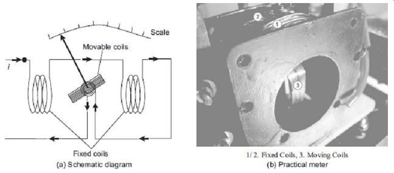
FIG. 16 Electrodynamometer-type instrument
2. Damping Air-friction damping is employed for these instruments and is provided by a pair of aluminum vanes, attached to the spindle at the bottom. These vanes move in a sector-shaped chamber.
9.1 Torque Equation of Electrodynamometer-type Instruments
Let, i1 = instantaneous value of current in the fixed coils, (A) i2 = instantaneous value of current in the moving coils, (A) L1 = self-inductance of fixed coils, (H) L2 = self-inductance of moving coil, (H) M = mutual inductance between fixed and moving coils (H) Flux linkage of Coil 1, ?1 = L1i1 + Mi2 Flux linkage of Coil 2, ?2 = L2i2 + Mi1
Electrical input energy,
Energy stored in the magnetic field
Change in energy stored =
From the principle of conservation of energy,
Total electrical input energy = Change in energy in energy stored + mechanical energy
The mechanical energy can be obtained by subtracting Eq. (35) from Eq. (34).
Therefore, mechanical energy =
Now, the self-inductances L1 and L1 are constants and, therefore, dL2 and dL2 both are equal to zero. Hence, mechanical energy = i1i2 dM
Suppose Ti is the instantaneous deflecting torque and d? is the change in deflection, then, Mechanical energy = work done = Ti d?
Thus we have 1. Operation with dc Let, I1 = current in the fixed coils, I2 = current in the moving coil
So deflecting torque Td = I1I2 . This shows that the deflecting torque depends in general on the product of current I1 and I2 and the rate of change of mutual inductance.
This deflecting torque deflects the moving coil to such a position where the controlling torque of the spring is equal to the deflecting torque. Suppose ? be the final steady deflection.
Therefore controlling torque TC = k? where k = spring constant (N-m/rad) At final steady position Td = TC If the two coils are connected in series for measurement of current, the two currents I1 and I2 are equal.
Say, I1 = I2 = I Thus, deflection of the pointer is For dc use, the deflection is thus proportional to square of the current and hence the scale non-uniform and crowded at the ends.
2. Operation with ac Let, i1 and i2 be the instantaneous values of current carried by the coils. Therefore, the instantaneous deflecting torque is:
If the two coils are connected in series for measurement of current, the two instantaneous currents i1 and i2 are equal.
Say, ii
= i2 = i Thus, instantaneous torque on the pointer is Ti
= i2
Thus, for ac use, the instantaneous torque is proportional to the square of the instantaneous current. As the quantity i 2 is always positive, the current varies and the instantaneous torque also varies. But the moving system due to its inertia cannot follow such rapid variations in the instantaneous torque and responds only to the average torque.
The average deflecting torque over a complete cycle is given by:
where T is the time period for one complete cycle.
At final steady position Td = TC
Thus, deflection of the pointer is Deflection is thus a function of the mean of the square of the current. If the pointer scale is calibrated in terms of square root of this value, i.e. square root of the mean of the square of current value, then rms value of the ac quantity can be directly measured by this instrument.
3. Sinusoidal Current
If currents i1 and i2 are sinusoidal and are displaced by a phase angle j, i.e.
i1 = im1 sin ?t and i2 = Im1 sin(wt - j)
The average deflecting torque where I1 and I2 are the rms values of the currents flowing through the coils. At equilibrium, Td = TC
As was in the case with ac measurement, with sinusoidal current also the deflection is a function of the mean of the square of the current. If the pointer scale is calibrated in terms of square root of this value, i.e. square root of the mean of the square of current value, then RMS value of the ac quantity can be directly measured by this instrument.
1. Electrodynamic Ammeter
In an electrodynamic ammeter, the fixed and moving coils are connected in series as shown in FIG. 17. A shunt is connected across the moving coil for limiting the current. The reactance-resistance ratio of the shunt and the moving coil is kept nearly same for independence of the meter reading with the supply frequency. Since the coil currents are the same, the deflecting torque is proportional to the mean square value of the current. Thus, the scale is calibrated to read the rms value.
2. Electrodynamic Voltmeter
The electrodynamic instrument can be used as a voltmeter by connecting a large noninductive resistance (R) of low temperature coefficient in series with the instrument coil as shown in FIG. 18.
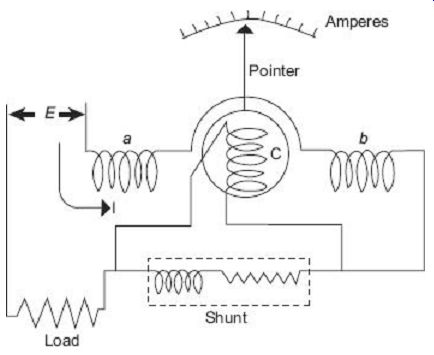
FIG. 17 Electrodynamometer ammeter
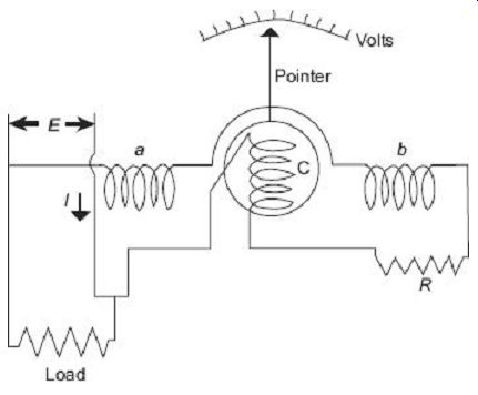
FIG. 18 Electrodynamometer voltmeter
3. Electrodynamic Wattmeter
The electrodynamic wattmeter consist of two fixed coils 'a' and 'b' placed symmetrical to each other and producing a uniform magnetic field. They are connected in series with the load and are called the Current Coils (CC). The two fixed coils can be connected in series or parallel to give two different current ratings. The current coils carry the full-load current or a fraction of full load current. Thus the current in the current coils is proportional to the load current. The moving coil 'c', in series with a high non inductive resistance Rv is connected across the supply. Thus the current flowing in the moving coil is proportional to, and practically in phase with the supply voltage. The moving coil is also called the voltage coil or Pressure Coil (PC). The voltage coil is carried on a pivoted spindle which carries the pointer, the pointer moved over a calibrated scale.
Two hair springs are used for providing the controlling torque and for leading current into and out of the moving coil. Damping is provided by air friction. FIG. 20 shows the basic arrangement of a electrodynamic wattmeter.
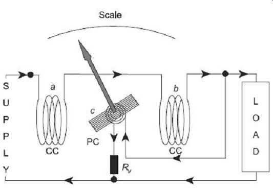
FIG. 19 Electrodynamic wattmeter
4. Torque Equation
Let, if = current in the fixed coil
im = current in the moving coil
i = load current
v = load voltage Tin = instantaneous value of the deflecting torque p = instantaneous power Tin x i f i m Thus, the instantaneous value of the deflecting torque is proportional to the instantaneous power. Owing to the inertia of the moving system, the pointer reads the average power. In dc circuits, the power is given by the product of voltage and current, and hence the torque is directly proportional to the power. Thus, the instrument indicates the power.
For ac, the instrument indicates the average power. This can be proved as follows:
Tin 8 Vi
Average deflecting torque × average power
Let, v = Vm sin d I = Im sin (? - ?)
Average deflecting torque 8 average value of
Vm sin d × Im sin (? - ?) 8 VI cos ?
If Td be the average torque, then where P is the true power and k is the constant.
For spring control TC = ks?1
Where:
TC is the control torque, ks is the spring constant and ?1 is the angle of deflection of the pointer.
For steady deflection,
Hence, in case of ac also the deflection is proportional to the true power in the circuit.
The scale of the electrodynamometer wattmeter is therefore uniform.
Advantages of Electrodynamometer-type Instruments
1. They can be used on ac as well as dc measurements.
2. These instruments are free from eddy current and hysteresis error.
3. Electrodynamometer-type instruments are very useful for accurate measurement of rms values of voltages irrespective of waveforms.
4. Because of precision grade accuracy and same calibration for ac and dc measurements these instruments are useful as transfer type and calibration instruments.
Disadvantages of Electrodynamometer-type Instruments
1. As the instrument has square law response, the scale is non-uniform.
2. These instruments have small torque/weight ratio, so the frictional error is considerable.
3. More costly than PMMC and MI type of instruments.
4. Adequate screening of the movements against stray magnetic fields is essential.
5. Power consumption is comparably high because of their construction.
The inductance of a 25 A electrodynamic ammeter changes uniformly at the rate of 0.0035 mH/radian. The spring constant is 10^-6 N-m/radian. Determine the angular deflection at full scale.
10. ELECTROSTATIC INSTRUMENTS
In electrostatic instruments, the deflecting torque is produced by action of electric field on charged conductors. Such instruments are essentially voltmeters, but they may be used with the help of external components to measure the current and power. Their greatest use in the laboratory is for measurement of high voltages.
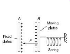
FIG. 20 Linear motion of electrostatic instruments FIG. 21 Rotary
motion of electrostatic instruments
Rotary motion of electrostatic instruments
There are two ways in which the force acts:
1. One type involves two oppositely charged electrodes. One of them is fixed and the other is movable. Due to force of attraction, the movable electrode is drawn towards the fixed one.
2. In the other type, there is force of attraction or repulsion between the electrodes which causes rotary motion of the moving electrode.
In both the cases, the mechanism resembles a variable capacitor and the force or torque is due to the fact that the mechanism tends to move the moving electrode to such a position where the energy stored is maximum.
10.1 Force and Torque Equation
1. Linear Motion Referring to FIG. 20, plate A is fixed and B is movable. The plates are oppositely charged and are restrained by a spring connected to the fixed point.
Let a potential difference of V volt be applied to the plates; then a force of attraction F Newton exists between them. Plate B moves towards A until the force is balanced by the spring. The capacitance between the plates is then C farad and the stored energy is ½ CV joules.
Now let there be a small increment dV in the applied voltage, then the plate B moves a small distance dx towards A. when the voltage is being increased a capacitive current flows. This current is given by:
The input energy is Change in stored energy = (neglecting the higher order terms as they are small quantities) From the principle of conservation of energy, Input electrical energy = increase in stored energy + mechanical work done 2. Rotational Motion The forgoing treatment can be applied to the rotational motion by writing an angular displacement ? in place of linear displacement x and deflecting torque Td instead of force F (FIG. 21).
Deflecting torque If the instrument is spring controlled or has a suspension then
Controlling torque TC = k&,
Where: k = spring constant
? = deflection
Hence, deflection
Since the deflection is proportional to the square of the voltage to be measured, the instrument can be used on both ac and dc. The instrument exhibits a square law response and hence the scale is non-uniform.
Advantages of Electrostatic Instruments
1. These instruments draws negligible amount of power from the mains.
2. They may be used on both ac and dc.
3. They have no frequency and waveform errors as the deflection is proportional to square of voltage and there is no hysteresis.
4. There are no errors caused by the stray magnetic field as the instrument works on the electrostatic principle.
5. They are particularly suited for high voltage.
Disadvantages of Electrostatic Instruments
1. The use of electrostatic instruments is limited to certain special applications, particularly in ac circuits of relatively high voltage, where the current drawn by other instruments would result in erroneous indication. A protective resistor is generally used in series with the instrument in order to limit the current in case of a short circuit between plates.
2. These instruments are expensive, large in size and are not robust in construction.
3. Their scale is not uniform.
4. The operating force is small.
11. INDUCTION-TYPE INSTRUMENTS
Induction-type instruments are used only for ac measurement and can be used either as ammeter, voltmeter or wattmeter. However, the induction principle finds its widest application as a watt-hour or energy meter (for details, refer Chapter 8). In such instruments, the deflecting torque is produced due to the reaction between the flux of an ac magnet and the eddy currents induced by another flux.
11.1 Principle of Operation
The operations of induction-type instruments depend on the production of torque due to the interaction between a flux F1 (whose magnitude depends on the current or voltage to be measured) and eddy current induced in a metal disc or drum by another flux F2 (whose magnitude also depends on the current or voltage to be measured). Since the magnitude of eddy current also depends on the flux producing them, the instantaneous value of the torque is proportional to the square of current or voltage under measurement and the value of mean torque is proportional to the mean square value of this current or voltage.
Consider a thin aluminum or copper disc D free to rotate about an axis passing through its centre as shown in FIG. 22. Two electromagnets P1 and P2 produce alternating fluxes F1 and F2 respectively which cuts this disc. Consider any annular portion of the disc around P1 with centre of the axis of Pl. This portion will be linked by flux F1and so an alternating emf F1 be induced in it. F2 will induce an emf e2 which will further induce an eddy current i2 in an annular portion of the disc around Pl. This eddy currents i2 flows under the pole Pl.
Let us take the downward directions of fluxes as positive and further assume that at the instant under consideration, both F1 and F2 are increasing. By applying Lenz's law, the direction of the induced currents i1 and i2 can be found as indicated in FIG. 22(b).
The portion of the disc which is traversed by flux F1 and carries eddy currents i2 experiences a force F1 along the direction as indicated. As F = Bil, force F1 8 F1i2.
Similarly, the portion of the disc lying under flux F2 and carrying eddy current i1 experiences a force F2 8 F2ij.
It is assumed that the constant k is the same in both the cases due to the symmetrical position of P1 and P2 with respect to the disc.
If r be the effective radius at which these forces acts, then net instantaneous torque T acting on the disc being equal to the different of the two torques, it is given by FIG. 22 Principle of operation of induction-type instrument Let the alternating flux f1 be given by f1 = f1m sin ?t. The flux f2 which is assumed to lag f1 by an angle a radian is given by f2 = f2m sin (? t - a) Induced emf e1 (f1m sin ?t) = ?f1m cos ?t Assuming the eddy current path to be purely resistive and of value R, then the value of eddy current is similarly, Substituting these values of i1 and i2 in Eq. (48), we get kw The following is observed:
1. If a = 0, i.e., if two fluxes are in phase, then net torque is zero. If, on the other hand, a = 90°, the net torque is maximum for a given values of f1m and f2m. 2. The net torque is such a direction as to rotate the disc from the pole with leading flux, towards the pole with lagging flux.
3. Since the expression for torque does not involve t, it is independent of time, i.e., it has a steady value at all times.
4. The torque T is inversely proportional to R; the resistance of the eddy current path. Hence, it is made of copper or more often, of aluminum.
12. ELECTROTHERMAL INSTRUMENTS
Mainly there are two types of thermal instruments:
• Hot-wire type
• Thermocouple instrument
Hot-wire and thermocouple meter movements use the heating effect of current flowing through a resistance to cause meter deflection. Each uses this effect in a different manner.
Since their operation depend only on the heating effect of current flow, they may be used to measure both direct and alternating currents of any frequency on a single scale.
12.1 Hot-wire Instrument
The hot-wire meter movement deflection depends on the expansion of a high resistance wire caused by the heating effect of the wire itself as current flows through it. A resistance wire is stretched between the two meter terminals, with a thread attached at a right angles to the centre of the wire. A spring connected to the opposite end of the thread exerts a constant tension on the resistance wire. Current flow heats the wire, causing it to expand.
This motion is transferred to the meter pointer through the thread and a pivot. FIG. 23 shows the basic arrangement of a hot wire type instrument.
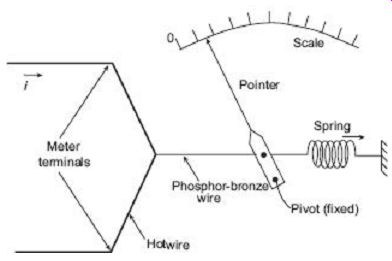
FIG. 23 Hot-wire instruments
Advantages of Hot-wire-type Instruments
1. The deflection depends upon only the rms value of the current flowing through the wire, irrespective if its waveform and frequency. Hence, the instrument can used for ac as well as dc system.
2. The calibration is same for ac as well as dc measurement. So it is a transfer-type instrument.
3. They are free from stray magnetic fields because no magnetic field is used to cause their operation.
4. It is cheap in cost and simple in construction.
5. With suitable adjustments, error due to temperature variation can be made negligible.
6. This type of instruments are quite suitable for very high frequency measurement.
Disadvantages of Hot-wire-type Instruments
1. Power consumption is relatively high.
2. Nonuniform scale.
3. These are very sluggish in action as time is taken in heating up the wire.
4. The deflection of the instrument is not the same for ascending and descending values.
5. The reading depends upon the atmospheric temperature.
12.2 Thermocouple-Type Instrument
When two metals having different work functions are placed together, a voltage is generated at the junction which is nearly proportional to the temperature of the junction.
This junction is called a thermocouple. This principle is used to convert heat energy to electrical energy at the junction of two conductors as shown in FIG. 24.
The heat at the junction is produced by the electrical current flowing in the heater element while the thermocouple produces an emf at its output terminals, which can be measured with the help of a PMMC meter. The emf produced is proportional to the temperature and hence to the rms value of the current. Therefore, the scale of the PMMC instrument can calibrate to read the current passing through the heater. The thermocouple type of instrument can be used for both ac and dc applications. The most effective feature of a thermocouple instrument is that they can be used for measurement of current and voltages at very high frequency. In fact, these instruments are very accurate well above a frequency of 50 MHz.
FIG. 24 Circuit diagram of thermocouple instrument
Advantages of Thermocouple-type Instruments
1. These are not affected by stray magnetic fields.
2. They have very high sensitivity.
3. The indication of these instruments are practically unaffected by the frequency and waveform of the measuring quantity. Hence these instruments can be used for measurement of currents up to frequencies of 50 MHz and give accuracy as high as 1%.
4. These instruments are very useful as transfer instruments for calibration of dc instruments by potentiometer and a standard cell.
Disadvantages of Thermocouple-Type Instruments
1. Considerable power losses due to poor efficiency of thermal conversion.
2. Low accuracy of measurement and sensitivity to overloads, as the heater operates at temperatures close to the limit values. Thus, the overload capacity of such instrument is approximately 1.5 times of full-scale current.
3. The multi-voltmeters used with thermo-elements must be necessarily more sensitive and delicate than those used with shunts, and therefore, requires careful handling.
2.13 RECTIFIER-TYPE INSTRUMENTS
The basic arrangement of a rectifier type of instrument using a full-wave rectifier circuit is shown in FIG. 25. If this instrument is used for measuring ac quantity then first the ac signal is converted to dc with the help of the rectifier. Then this dc signal is measured by the PMMC meter. The multiplier resistance Rs, is used to limit the value of the current in order that it does not exceed the current rating of the PMMC meter.
These types of instruments are used for light current work where the voltage is low and resistances high.
FIG. 25 Rectifier-type instrument
13.1 Sensitivity of Rectifier-Type Instrument
The dc sensitivity of a rectifier-type instrument is where Ifs is the current required to produce full-scale deflection.
1. Sensitivity of a Half-wave Rectifier Circuit
FIG. 26 Half-wave rectifier
FIG. 26 shows a simple half-wave rectifier circuit along with the input and output waveform. The average value of voltage/current for half-wave rectifier, Hence, the sensitivity of a half-wave rectifier instrument with ac is 0.45 times its sensitivity with dc and the deflection is 0.45 times that produces with dc of equal magnitude V.
2. Sensitivity of a Full-wave Rectifier Circuits
FIG. 27 Full-wave rectifier
FIG. 27 shows a full-wave rectifier circuit along with the input and output waveform.
Average value of voltage/current for full-wave rectifier, So the deflection is 0.9 times in a full-wave rectifier instrument with an ac than that produced with dc of equal magnitude V.
Sensitivity of a full-wave rectifier instrument with an ac is 0.9 times its sensitivity with dc.
13.2 Extension of Range of Rectifier Instrument as Voltmeter
Suppose it is intended to extend the range of a rectifier instrument which uses a PMMC instrument having a dc sensitivity of Sdc.
Let, v = voltage drop across the PMMC instrument
V = applied voltage
Therefore, for dc operation, the values of series resistance (multiplier) needed can be calculated from FIG. 28 as V = RS . Ifs + Rd . Ifs + Rm . Ifs FIG. 28 Range extension of rectifier voltmeter where Rm = meter resistance Rd = diode forward resistance For ac voltmeter, Limitations 1. Rectifier instruments are only accurate on the waveforms on which they are calibrated. Since calibration assumes pure sine waves, the presence of harmonics gives erroneous readings.
2. The rectifier is temperature sensitive, and therefore, the instrument readings are affected by large variations of temperature.
Applications
1. The rectifier instrument is very suitable for measuring alternating voltages in the range of 50-250 V.
2. The rectifier instrument may be used as a micrometer or low milliammeter (up to 10-15 mA). It is not suitable for measuring large currents because for larger currents the rectifier becomes too bulky and providing shunts is impracticable due to rectifier characteristics.
3. Rectifier instruments find their principal application in measurement in high-impedance circuits at low and audio frequencies. They are commonly used in communications circuits because of their high sensitivity and low power consumption.
14. TRUE rms VOLTMETER
The commonly available multimeters are average or peak reading instruments, and the rms values they display are based on the signal mean value. They multiply the average value with some factor to convert it to the rms reading. For this reason, conventional multimeters are only suited for sinusoidal signals. For measuring rms value of a variety of signals over a wide range of frequencies, a new kind of voltmeter-called the True RMS (TRMS) voltmeter has been developed. Since these voltmeters do not measure rms value of a signal based on its average value, they are suited for any kind of waveforms (such as sine wave, square wave or sawtooth wave).
The conventional moving-iron voltmeter has its deflection proportional to the square of the current passing through its coil. Thus, if the scale is calibrated in terms of square root of the measured value, moving-iron instruments can give true rms value of any signal, independent of its wave shape. However, due to large inertia of the mechanical moving parts present in such a moving iron instrument, the frequency bandwidth of such a true rms voltmeter is limited. Similar is the case for electrodynamometer type instruments which once again have their deflecting torque proportional to the current through their operating coil. But once again, though electrodynamometer-type instruments can give true rms indication of a signal of any waveform, their frequency bandwidth is also limited due to their mechanical moving parts.
Modern-day true rms reading voltmeters are made to respond directly to the heating value of the input signal. To measure rms value of any arbitrary waveform signal, the input signal is fed to a heating element and a thermocouple is placed very close to it. A thermocouple is a junction of two dissimilar metals whose contact potential is a function of the temperature of the junction. The heating value is proportional to the square of the rms value of the input signal. The heater raises the temperature of the heater and the thermocouple produces an output voltage that is proportional to the power delivered to the heater by the input signal. Power being proportional to the square of the current (or voltage) under measurement, the output voltage of the thermocouple can be properly calibrated to indicate true rms value of the input signal. This way, such a thermal effect instrument permits the determination of true rms value of an unknown signal of any arbitrary waveform. Bandwidth is usually not a problem since this kind of principle can be used accurately even beyond 50 MHz. FIG. 28 shows such an arrangement of thermocouple based true rms reading voltmeter.
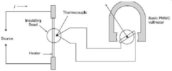
FIG. 28 Thermocouple based true rms reading voltmeter
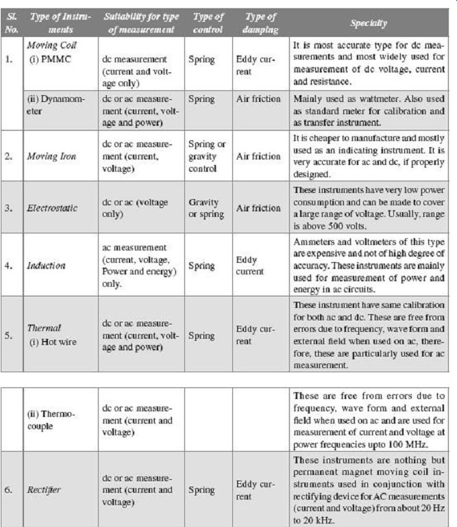
15. COMPARISON BETWEEN DIFFERENT TYPES OF INSTRUMENTS
QUIZ
Objective Questions
1. A spring produces a controlling torque of 16x10^-6 Nm for a deflection of 120Y. If the width and length become two times their original values and the thickness is halved, the value of controlling torque for the same deflection will be
(a) 16 × 10^-6 N
(b) 8x10^-6 Nm
(c) 2x10^-6 Nm
(d) 32x10^-6 Nm
2. The shunt resistance in an ammeter is usually (a) less than meter resistance (b) equal to meter resistance (c) more than meter resistance (d) of any value
3. A voltage of 200 V produces a deflection of 90° in a PMMC spring-controlled instrument. If the same instrument is provided with gravity control, what would be the deflection?
(a) 45°
(b) 65°
(c) 90°
(d) cannot be determined by the given data
4. A current-carrying conductor is shown in Figure (a). If it is brought in a magnetic field shown in Figure (b)
(a) it will experience a force from left to right.
(b) it will experience a force from right to left.
(c) it will experience a force from top to bottom.
(d) it will experience no force.
5. The high torque to weight ratio in an analog indicating instrument indicates (a) high friction loss (b) nothing as regards friction loss (c) low friction loss (d) none of the above
6. Swamping resistance is connected (a) in series with the shunt to reduce temperature error in shunted ammeter (b) in series with the ammeters to reduce errors on account of friction (c) in series with meter and have a high resistance temperature coefficient in order to reduce temperature errors in ammeters.
(d) in series with the meter and have a negligible resistance co-efficient in order to reduce temperature errors in shunted ammeters
7. Moving-iron instruments when measuring voltages or currents (a) indicate the same values of the measurement for both ascending and descending values (b) indicate higher value of measurand for ascending values (c) indicate higher value of measurand for descending values (d) none of the above
8. A moving-iron type of instrument can be used as (a) standard instruments for calibration of other instruments (b) transfer-type instruments (c) indicator-type instruments as on panels (d) all of the above
9. In spring-controlled moving iron instruments, the scale is (a) uniform (b) cramped at the lower end and expanded at the upper end (c) expanded at the lower end and cramped at the upper end (d) cramped both at the lower and the upper ends
10. Thermocouple instruments can be used for a frequency range (a) up to 500 Hz (b) up to 5 MHz (c) up to 100 Hz (d) up to 1 MHz
11. The reason why eddy-current damping cannot he used in a moving-iron instrument, is (a) they have a strong operating magnetic field (b) they are not normally used in vertical position (c) they need a large damping force which can only he provided by air friction (d) they have a very weak operating magnetic field and introduction of a permanent magnet required for eddy current damping would distort the operating magnetic field
12. An electrodynamometer type of instrument finds its major use as (a) standard instrument only (b) both as standard and transfer instrument (c) transfer instrument only (d) indicator-type instrument
13. The frequency range of moving-iron instruments is (a) audio-frequency band 20 Hz to 20 kHz (b) very low-frequency band 10 Hz to 30 kHz (c) low-frequency band 30 Hz to 300 kHz (d) power frequencies 0 to 125 Hz.
14. A voltage of 200 V at 5 Hz is applied to an electrodynamometer type of instrument which is spring controlled. The indication on the instruments is (a) 200 V (b) 0 V (c) the instrument follows the variations in voltage and does not give a steady response (d) none of the above
15. Spring-controlled moving-iron instruments exhibit a square law response resulting in a non-linear scale. The shape of the scale can be made almost linear by (a) keeping rate of change of inductance, L, with deflection, ?, as constant (b) keeping as constant (c) keeping as constant (d) keeping as constant, where k is the spring constant
16. Electrostatic-type instruments are primarily used as (a) ammeters (b) voltmeters (c) wattmeters (d) ohmmeters
17. The sensitivity of a PMMC instrument is 10CkZ/V. If this instrument is used in a rectifier-type voltmeter with half wave rectification. What would be the sensitivity?
(a) 10 kO/V
(b) 4.5 kO/V
(c) 9 kO/V
(d) 22.2 kO/V
18. The heater wire of thermocouple instrument is made very thin in order (a) to have a high value of resistance (b) to reduce skin effects at high frequencies (c) to reduce the weight of the instrument (d) to decrease the over-ranging capacity of the instrument
19. Which instrument has the highest frequency range with accuracy within reasonable limits? (a) PMMC (b) Moving iron (c) Electrodynamometer (d) Rectifier
20. Which meter has the highest accuracy in the prescribed limit of frequency range? (a) PMMC (b) Moving iron (c) Electrodynamometer (d) Rectifier
Questions:
1. Describe the various operating forces needed for proper operation of an analog indicating instrument.
2. Sketch the curves showing deflection versus time for analog indicating instruments for underdamping, critical damping and overdamping.
3. What are the difference between recording and integrating instruments? Give suitable examples in each case.
4. Derive the equation for deflection of a PMMC instrument if the instrument is spring controlled.
5. How can the current range of a PMMC instrument be extended with the help of shunts?
6. Derive the equation for deflection of a spring-controlled moving-coil instrument.
7. Describe the working principle of a rectifier-type instrument. What is the sensitivity of such an instrument?
8. What are the advantages and disadvantages of a PMMC instrument?
9. Describe the working principle and constructional details of an attraction-type moving iron instrument.
10. Derive the expression for deflection for a rotary-type electrostatic instrument using spring control.
11. What is swamping resistance? For what purpose is swamping resistance used?
12. How many ways can the damping be provided in an indicating instrument?
More Questions:
1. (a) How many operating forces are necessary for successful operation of an indicating instrument? Explain the methods of providing these forces. (b) A moving-coil instrument has the following data: number of turns = 100, width of coil = 20 mm, depth of coil = 30 mm, flux density in the gap = 0.1 Wb/m^2. Calculate the deflecting torque when carrying a current of 10 mA. Also calculate the deflection if the control spring constant is 2 × 10^-6 N-m/degree.
[Ans. 60 × 10-6 Nm, 30°]
2. (a) What are the advantages and disadvantages of moving-coil instruments? (b) A moving-coil voltmeter has a resistance of 200 W and the full scale deflection is reached when a potential difference of 100 mV is applied across the terminals. The moving coil has effective dimensions of 30 mm × 25 mm and is wound with 100 turns. The flux density in the gap is 0.2 Wb/m^2. Determine the control constant of the spring if the final deflection is 100° and a suitable diameter of copper wire for the coil winding if 20% of the total instrument resistance is due to the coil winding. Resistivity of copper is 1.7 × 10^-8 ?m.
[Ans. 0.075 × 10^-6 Nm/degree; 0.077 mm]
3. (a) Derive the expression for the deflection of a spring controlled permanent magnet moving coil instrument.
Why not this instrument able to measure the ac quantity? (b) The coil of a moving coil voltmeter is 40 mm × 30 mm wide and has 100 turns wound on it. The control spring exerts a torque of 0.25 × 10^-3 Nm when the deflection is 50 divisions on the scale. If the flux density of the magnetic field in the air-gap is 1 Wb/m2, find the resistance that must be put in series with the coil to give 1 volt per division. Resistance of the voltmeter is 10000 ?.
[Ans. 14000 Q]
4. (a) A moving-coil instrument has at normal temperature a resistance of 10 W and a current of 45 mA gives full scale deflection. If its resistance rises to 10.2 ? due to temperature change, calculate the reading when a current of 2000 A is measured by means of a 0.225 × 10^-3. A shunt of constant resistance. What is the percentage error?
[Ans. 44.1 mA, -1.96%]
(b) The inductance of a certain moving-iron ammeter is pH, where 0 is the deflection in radian from the zero position. The control spring torque is 12 × 10-6 Nm/rad. Calculate the scale position in radian for current of 5 A. [2.04 rad]
5. (a) Discuss the constructional details of a thermocouple-type instrument used at very high frequencies. Write their advantages and disadvantages.
(b) The control spring of a moving-iron ammeter exerts a torque of 0.5 × 10- Nm/degree when the deflection is 52°. The inductance of the coil varies with pointer deflection according to deflection (degree) 20 40 60 80 inductance (|mH) 659 702 752 792 Determine the current passing through the meter.
[0.63 A]
6. (a) Describe the constructional details of an attraction-type moving iron instrument with the help of a neat diagram. Derive the equation for deflection if spring control is used and comment upon the shape of scale.
(b) Derive a general equation for deflection for a spring-controlled repulsion-type moving-iron instrument.
Comment upon the share of the scale. Explain the methods adopted to linearize the scale.