AMAZON multi-meters discounts AMAZON oscilloscope discounts
1. INTRODUCTION
Instrument transformers are used in connection with measurement of voltage, current, energy and power in ac circuits. There are principally two reasons for use of instrument transformers in measurement: first, to extend (multiply) the range of the measuring instrument and second, to isolate the measuring instrument from a high-voltage line.
In power systems, levels of currents and voltages handled are very high, and, therefore, direct measurements with conventional instruments is not possible without compromising operator safety, and size and cost of instrument. In such a case, instrument transformers can be effectively used to step down the voltage and current within range of the existing measuring instruments of moderate size. Instrument transformers are either (a) current transformer or CT, or (b) voltage or potential transformers or PT. The former is used to extend current ranges of instruments and the latter for increasing the voltage ranges.
Instrument transformers have their primary winding connected to the power line and secondary windings to the measuring instrument. In this way, the measuring instruments are isolated from the high power lines. In most applications, it is necessary to measure the current and voltage of large alternators, motors, transformers, buses and other power transmission equipments for metering as well as for relaying purposes. Voltages in such cases may range from 11,000 to even 330,000 V. It would be out of question to bring down these high-voltage lines directly to the metering board. This will require huge insulation and pose great danger for operating personnel otherwise. In such a case, instrument transformers can greatly solve this problem by stepping down the high voltage to safe levels for measurement.
2. ADVANTAGES OF INSTRUMENT TRANSFORMERS
Shunt and multipliers used for extension of instrument ranges are suitable for dc circuits and to some extent, for low power, low accuracy ac circuits. Instrument transformers have certain distinguishing characteristics as compared to shunts and multipliers, as listed below.
1. Using shunts for extension of range on ammeters in ac circuits will require careful designing of the reactance and resistance proportions for the shunt and the meter.
Any deviation from the designed time constants of the shunt and the meter may lead to errors in measurement. This problem is not present with CT being used with ammeter.
2. Shunts cannot be used for circuits involving large current; otherwise the power loss in the shunt itself will become prohibit-ably high.
3. Multipliers, once again, due to inherent leakage current, can introduce errors in measurement, and can also result in unnecessary heating due to power loss.
4. Measuring circuits involving shunts or multipliers, being not electrically isolated from the power circuit, are not only safe for the operator, but also insulation requirements are exceedingly high in high-voltage measurement applications.
5. High voltages can be stepped down by the PT to a moderate level as can be measured by standard instruments without posing much danger for the operator and also not requiring too much insulation for the measuring instrument.
6. Single range moderate size instruments can be used to cover a wide range of measurement, when used with a suitable multi-range CT or PT.
7. Clamp-on type or split-core type CT's can be very effectively used to measure current without the need for breaking the main circuit for inserting the CT primary winding.
8. Instrument transformers can help in reducing overall cost, since various instruments, including metering, relaying, diagnostic, and indicating instruments can all be connected to the same instrument transformer.
3. CURRENT TRANSFORMERS (CT)
The primary winding of a current transformer is connected in series with the line carrying the main current. The secondary winding of the CT, where the current is many times stepped down, is directly connected across an ammeter, for measurement of current; or across the current coil of a wattmeter, for measurement of power; or across the current coil of a watt-hour meter for measurement of energy; or across a relay coil. The primary winding of a CT has only few turns, such that there is no appreciable voltage drop across it, and the main circuit is not disturbed. The current flowing through the primary coil of a CT, i.e., the main circuit current is primarily determined by the load connected to the main circuit and not by the load (burden) connected to the CT secondary. Uses of CT for such applications are schematically shown in FIG. 1.
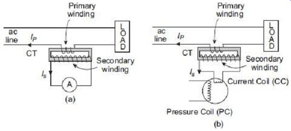
FIG. 1 CT for (a) current, and (b) power measurement
One of the terminals of the CT is normally earthed to prevent any accidental damage to the operating personnel in the event of any incumbent insulation breakdown.
When a typical name plate rating of a CT shows 500/1 A 5 VA 5P20 it indicates that the CT rated primary and secondary currents are 500 A and 1 A respectively, its rated secondary burden is 5 VA, it is designed to have 5% accuracy and it can carry up to 20 times higher current than its rated value while connected in line to detect fault conditions, etc.
4. THEORY OF CURRENT TRANSFORMERS
FIG. 2 represents the equivalent circuit of a CT and FIG. 3 plots the phasor diagram under operating condition of the CT.
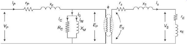
FIG. 2 Equivalent circuit of a CT FIG. 3 Phasor diagram of a CT
VP = primary supply voltage EP = primary winding induced voltage VS = secondary
terminal voltage
ES = secondary winding induced voltage IP = primary current IS = secondary current I0 = no-load current IC = core loss component of current IM = magnetizing component of current rP = resistance of primary winding xP = reactance of primary winding rS = resistance of secondary winding xS = reactance of secondary winding RC = imaginary resistance representing core losses XM = magnetizing reactance re = resistance of external load (burden) including resistance of meters, current coils, etc.
xE = reactance of external load (burden) including reactance of meters, current coils, etc.
NP = primary winding number of turns NS = secondary winding number of turns n = turns ratio = NS /NP f = working flux of the CT
? = the "phase angle" of the CT d = phase angle between secondary winding induced voltage and secondary winding current (i.e. phase angle of total burden, including secondary winding)
ß = phase angle of secondary load (burden) circuit only a = phase angle between no-load current I0 and flux f The flux f is plot along the positive x-axis. Magnetizing component of current IM is in phase with the flux. The core loss component of current Ic, leads by IM 90°. Summation of IC and IM produces the no-load current I0, which is a angle ahead of flux f.
The primary winding induced voltage EP is in the same phase with the resistive core loss component of the current IC. As per transformer principles, the secondary winding induced voltage ES will be 180° out of phase with the primary winding induced voltage EP. The secondary current IS lags the secondary induced voltage ES by angle d.
The secondary output terminal voltage VS is obtained by vectorically subtracting the secondary winding resistive and reactive voltage drops IS rS and IS xS respectively from the secondary induced voltage ES. The phase angle difference between secondary current IS and secondary terminal voltage VS is ß, which is the phase angle of the load (burden).
The secondary current IS, when reflected back to primary, can be represented by the 180° shifted phasor indicated by nIS, where n is the turns ratio. The primary winding current IP is the phasor summation of this reflected secondary current (load component) nIS and the no-load current I0.
The phase angle difference ? between the primary current IP and the reflected secondary current nIS is called phase angle of the CT.
4.1 Current Transformation Ratio of CT
Redrawing expanded view of the phasor diagram of FIG. 3, we obtain the phasor diagram of FIG. 4.
FIG. 4 Expanded view of a section of FIG. 3 From the right-angle triangle pqr , we get pr = I0 pq = I0 · cos(90° - d - a) = I0 · sin(d + a) qr = I0 · sin(90° - d - a) = I0 · cos(d + a) Now, (or) 2 = (op + pq) 2 + (qr) 2 Or, (Ip) 2 = (nIS +I0 · sin(d + a)) 2 + (I0 . cos(d + a)) 2 = n2IS 2 +I0 2 · sin2 (d + a) + 2nISI0 . sin(d + a) +I0 2 . cos2 (d + a) = n2IS 2 + 2nISI0. sin(d + a) +I0 2 (sin2 (d + a) + cos2 (d + a)) = n2IS 2 + 2nISI0 · sin(d + a) +I0 2
In a well-designed CT, the no-load current I0 is much less as compared to the primary current Ip or even the reflected secondary current (which is nominally equal to the primary current) nIS. i.e., I0<< nIs
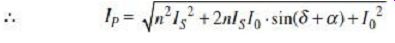
Eq. (1) can thus now be approximated as IP = Hence, Ip = nIS +I0 . sin(d + a) CT transformation ratio can now be expressed as Though approximate, Eq. (2) is sufficiently accurate for practical estimation of CT transformation ratio. The above equation, however, is true for only when the power factor of the burden is lagging, which is mostly true in all practical inductive meter coils being used as burden.
Eq. (2) can be further expanded as or, transformation ratio
[since, IM = I0 cos a and IC = I0 sin a ]
4.2 Phase Angle of CT
As can be seen from the phasor diagram in FIG. 3, the secondary current of a CT is almost 180° out of phase from the primary current. If the angle was exactly 180° then there would have been no phase angle error introduced in the CT when it is to be used along with wattmeter for power measurements. In reality, however, due to presence of the parallel circuit branches, namely, the magnetizing and the core loss branches, the phase angle difference is usually less than 180°. This causes some error in phase to be introduced while CT operation in practice.
The angle by which the secondary current phasor, when reversed, i.e., the reflected secondary current phasor nIS, differs in phase from the primary current IP, is called the phase angle of the CT. This angle is taken as positive when the reversed secondary current leads the primary current, in other cases when the reversed secondary current lags the primary current, the CT phase angle is taken as negative.
From the phasor diagram in FIG. 4, For very small angles, This expression can still be simplified with the assumption I0 << nIS.
rad Or, rad Or, phase angle of CT degree
5. ERRORS INTRODUCED BY CURRENT TRANSFORMERS
When used for current measurement, the only essential requirement of a CT is that its secondary current should be a pre-defined fraction of the primary current to be measured.
This ratio should remain constant over the entire range of measurement, such that no errors are introduced in the measurement. However, from Eq. (3), it is clear that the transformation ratio R of the CT differs from the turns ratio n . This difference is not constant, but depends on the magnitude of magnetizing and loss components of no-load current, and also on the secondary winding load current and its phase angle. The secondary winding current thus is never a constant fraction of the primary winding current under all conditions of load and of frequency. This introduces considerable amount of error in current measurement.
While power measurements, it is required that the secondary current of CT is displaced exactly by 180° from the primary current. As seen from Eq. (6), this condition is not fulfilled, but the CT has a phase angle error ?. This will introduce appreciable error during power measurements.
5.1 Ratio Error
Ratio error is defined as:
In practice, the CT burden is largely resistive with a small value of inductance, thus the secondary phase angle d is positive and generally small. The nominal ratio Kn, is sometimes loosely taken equal to the turns ratio n . This assumption, as will be described in later sections, is true in the case when turns compensation is not used in CT.
Thus, sin d ˜ 0 and cos d ˜ 1. Therefore, Eq. (3) can be approximated as Accordingly, percentage ratio error can be approximated as Percentage ratio error =
5.2 Phase-Angle Error
Error in phase angle is given following Eq. (6) as In practice, the CT burden is largely resistive with a small value of inductance, thus the secondary phase angle d is positive and generally small.
Thus, sin d ˜ 0 and cos d ˜ 1. Therefore, Eq. (10) can be approximated as
5.3 Causes of Errors in CT
In an ideal CT, the actual transformation ratio should have been exactly equal to the turns ratio and the phase angle should have been zero. However, due to inherent physical limitations inherent to the electric and magnetic circuits of the CT, practical performance deviates from these ideal behaviors and errors are introduced in measurement. The reasons for these errors are given here.
1. Primary winding always needs some magnetizing MMF to produce flux and, therefore, the CT draws the magnetizing current IM.
2. CT no-load current must have a component Ic that has to supply the core losses, i.e., the eddy current loss and the hysteresis loss.
3. Once the CT core becomes saturated, the flux density in the core no longer remains a linear function of the magnetizing force, this may introduce further errors.
4. Primary and secondary flux linkages differ due to unavoidable flux leakages.
5.4 Reducing Errors in CT
Errors are produced in the ratio and phase angle of a CT owing to the presence of the no load component of the primary current. Improvement of accuracy, then, depends upon minimizing this component or nullifying in some way its effects in introducing errors. The most obvious idea would be to attempt to keep the magnetizing current component as small as possible. This can be achieved by a combination of the following schemes:
1. Low Flux Density
The magnetizing component of current may be restricted by using low values of flux density. This may be achieved by using large cross-section for core. For this reason, CTs are normally designed with much lower flux densities as compared to a normal power transformer.
2. High Permeability Core Material
The magnetizing component of current may be made small by the use of high permeability core material. Some special core materials, such as Permalloy, are even better than the highest grade silicon steel with respect to permeability, particularly at lower flux densities.
Hipernik (50% Fe + 50% Ni) has high permeability at low flux densities along with reasonably high saturation density value. It is used frequently as core material for manufacturing CTs.
3. Modification of Turns Ratio
The accuracy of current transformers may be improved, at least in terms of transformation ratio, by suitably modifying the actual number of turns. Instead of using the number of turns in exact accordance with the desired nominal ratio, a change in few numbers of turns may be made in the secondary winding. Primary number of turns itself being so less, any change in number of turns in the primary may result in wide variation of the turns ratio.
For normal operating conditions, the usual secondary current is found to be less than the nominal value due to the no-load current. Correction in such cases, thus, may be made by a small reduction in the secondary number of turns. This correction can, however, be exact only for particular value of current and burden impedance. CTs in such cases are normally marked as 'compensated' for that particular operating condition.
4. Use of Shunts
If the secondary current is found to be too high, it may be reduced by a shunt placed across primary or secondary. This method can make an exact correction, once again, only for a particular value and type of burden. Use of shunts can also help in reducing the phase-angle error.
5. Wound-Core Construction
An improvement in the magnetization characteristics of the CT core may be achieved by the use of wound-core construction. This type of construction for the core has been in use for some time in distribution transformers. By special treatment of the silicon steel to be used as core material, and by using it to carry flux always in the direction of grain orientation (rolling the sheet steel in proper way), magnetic properties of the core can be largely improved. This improvement may be utilized in CTs to reduce the ratio and phase angle errors.
6. OPERATIONAL CHARACTERISTICS OF CURRENT TRANSFORMERS
Characteristics of current transformers under different operating conditions may be estimated from the phasor diagram as shown in FIG. 3.
6.1 Effect of Change in Burden on Secondary Circuit
Burden connected with the CT secondary may include ammeters, wattmeter current coils, relay coils, and so forth. All these being connected in series, carry the same current through them. In a current transformer, since the current depends solely on the primary current, an increase in the burden impedance will not change the secondary current, but will demand more voltage in the secondary terminals. This will increase volt-ampere burden of the secondary. With more instruments in the circuit, a higher voltage is required to make the current flow and this, in turn, requires more flux to flow through the core and hence a greater magnetizing component of the primary current. This will result in an increase in the ratio and phase angle error of the current transformer. FIG. 5 summarizes the variations of ratio and phase angle errors in a typical current transformer at different values of the secondary burden VA.
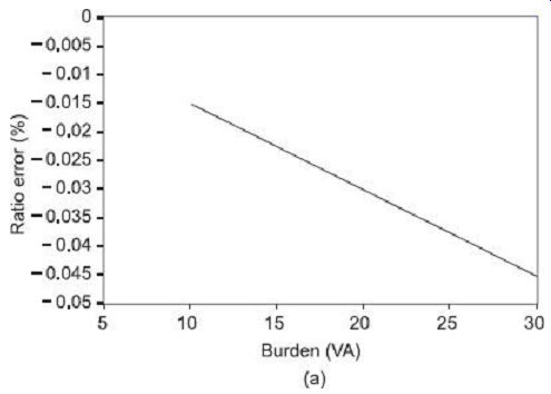
FIG. 5 Effects of secondary burden variation on (a) CT ratio error ,
and (b) CT phase-angle error
6.2 Effect of Change in Power Factor of Secondary Burden
1. Ratio Error
As can be observed from the phasor diagram of a current transformer in FIG. 3, for all inductive burdens, the secondary winding current IS lags behind the secondary induced voltage ES, so that the phase angle difference d is positive. Under these conditions, from Eq. (2), the actual transformation ratio is always greater than the turns ratio, and thus according to Eq. (9), ratio error is always negative for inductive (lagging power factor) burdens.
For highly capacitive burdens, the he secondary winding current IS leads the secondary induced voltage ES, so that the phase angle difference d is negative. In such a case, the actual transformation ratio may even become less than the turns ratio and ratio error may thus become positive.
2. Phase-Angle Error
From Eq. (5) it is observed that for inductive burdens, the phase angle error remains positive till a certain low value of power factor is reached at highly inductive burdens when the phase angle error crosses over the axis to turn negative. For capacitive burdens, however, the phase-angle error always remains positive.
FIG. 6 shows the variations of ratio and phase-angle errors in a typical current transformer at different values of the secondary burden power factor. These variations are described with the assumption of secondary burden VA to remain constant.
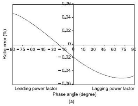
FIG. 6 Effects of secondary burden power factor variation on (a) CT
ratio error, and (b) CT phase-angle error.
6.3 Effect of Change in Primary Winding Current
As the primary winding current Ip changes, the secondary winding current Is also changes proportionately. With lower values of Ip (and Is), the magnetizing and loss components of no-load current become comparatively higher, and, therefore, both of ratio and phase angle errors become higher. As the primary current Ip increases, the secondary current IS also increases, thereby reducing the proportions of magnetizing and loss components of currents, which reduces the ratio and phase angle errors. These observations can be verified following Eqs (2) and (5).
Such variations of CT errors with changing primary (and hence secondary) current under a typical unity power factor burden are shown in FIG. 7.
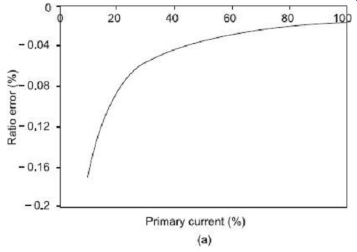
FIG. 7 Effects of primary current variation on (a) CT ratio error ,
and (b) CT phase-angle error
7. DESIGN AND CONSTRUCTIONAL FEATURES OF CURRENT TRANSFORMERS
7.1 Design Features
1. Number of Primary Ampere-Turns (AT)
One of the primary conditions for restricting ratio and phase-angle errors is that the magnetizing ampere-turns in the primary shall be only a small proportion of the total primary ampere turns. To satisfy this condition, in most practical cases, the number of primary ampere-turns may be estimated as to be in the range 5000-10000. In the case of CTs having a single bar as their primary winding, the number of primary ampere turns is, of course, determined by the primary current. For most practical purposes, with commercially available magnetic materials at the core of the CT, primary currents not less than 100 A have proved to be necessary for producing satisfactory amount of ampere turns.
2. Core
To satisfy the condition of achieving low magnetizing ampere-turns, the core material must have a low reluctance and low iron loss. The flux density in the core also needs to be restricted to low values. Core materials such as Mumetal (an alloy of iron and nickel containing copper) has properties of high permeability, low loss, and low retentivity-all of which are advantageous for being used in CTs. Mumetal, however, has the disadvantage of having low saturation flux densities.
The length of magnetic path in the core should be as small as permissible from the point of view of mechanical construction and with proper insulation requirements in order to reduce the core reluctance. For similar reasons, core joints should be avoided as far as practicable, or in other case, core joints must be as efficient as possible by careful assembly.
3. Windings
Primary and secondary windings should be placed close together to reduce the leakage reactance; otherwise the ratio error will go up. Thin SWG wires are normally used for secondary winding, whereas copper strips are generally used for primary winding, dimensions of which depend, obviously, upon the primary current.
The windings need to be designed for proper robustness and tight bracing with a view to withstand high mechanical forces without damage. Such mechanical forces my get developed due to sudden short circuits in the system where the CT is connected.
4. Insulation
Lower voltage rating applications allow windings to be insulated with tape and varnish. Higher voltage applications, however, require oil-immersed insulation arrangements for the winding. Still high voltages may require use of solid compound insulation systems.
7.2 Constructional Features
1. Indoor Type CTs
For indoor table/panel mounted applications, winding construction can be of two types in a CT: (i) wound type, and (ii) bar type.
In wound-type winding, the primary winding consists of a few turns of heavy conductor to whose projected ends, the primary conductor, cable or bus bar is bolted. The secondary winding, which composes of a large number of turns, is wound over a Bakelite former around a central core. The heavy primary conductor is either wound directly on top of the secondary winding, suitable insulation being first applied over the secondary winding, or the primary is wound entirely separately, insulated with suitable tape and then assembled with the secondary winding on the core. The entire system is housed, normally, within a molded insulation cover. FIG. 8(a) shows a schematic diagram of the cross section of a wound-type CT. FIG. 8 (b) shows a photograph of such a wound-type CT.
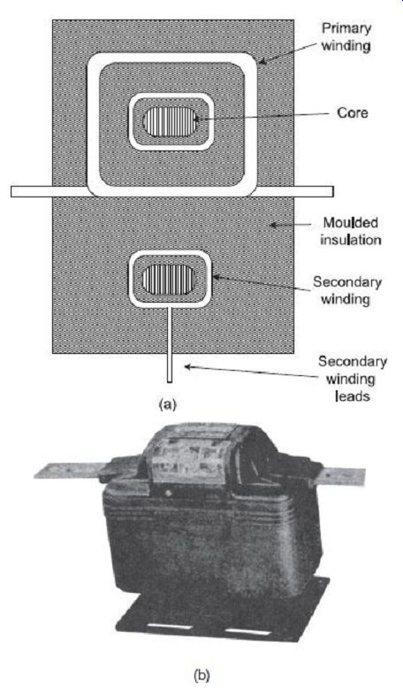
FIG. 8
(a) Cross section of wound-type CT (b) Butyl-molded wound primary type indoor
CT (General Electric Company)
The bar-type CT includes the laminated core and secondary winding but no primary winding as such. The primary consists of the bus-bar or conductor, which is passed through the opening in the insulating sleeve through the secondary winding. The primary winding (bar) here forms an integral part of the CT. Such CTs are sometimes termed as single-turn primary-type CT. The external diameter of the bar type primary must be large enough to keep the voltage gradient in the dielectric at its surface, to an acceptable value such that corona effect can be avoided. FIG. 9 shows a schematic diagram of the cross section of a bar-type CT. FIG. 10 show photograph of such bar-type CTs.
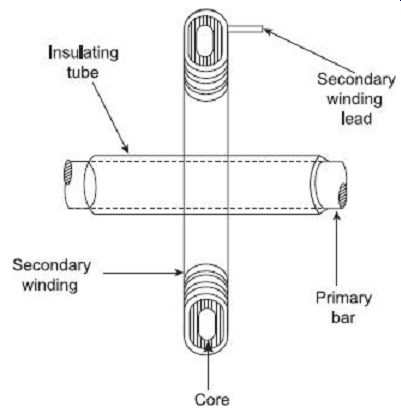
FIG. 9 Cross section of bar-type CT FIG. 10 (a) Butyl-molded bar
primary-type indoor CT for 200-800 A and 600 V range circuit (Courtesy of
General Electric Company) (b) Single conductor (bar type) primary CT 2. Clamp-on
Type or Portable Type CTs By the use of a construction with a suitably split
and hinged core, upon which the secondary winding is wound, it is possible
to measure the current in a heavy-current conductor or bus-bar without breaking
the current circuit. The split core of the CT along with the secondary winding
is simply clamped around the main conductor, which acts as the primary winding
of the CT. When used with range selectable shunts and a calibrated ammeter,
clamp on type CTs can be very conveniently used for direct and quick measurement
of current. FIG. 11 shows photograph of such a clamp-on type CT.

FIG. 11 Multi-range clamp-on type CT
A portable-type CT in which high and largely adjustable current ranges can be obtained by actually winding the primary turns through the core opening is illustrated in FIG. 12. For example, if one turn of the primary conductor through the opening gives a current ratio of 800/5, then two primary turns through the same opening will give a current ratio of 400/5, and so on.
FIG. 12 Multi-range portable type CT Yokogawa)
3. Bushing-type CTs
The bushing-type CT is similar in concept to the bar type in the sense that core and secondary winding are mounted around the single primary conductor. It has a circular core that carries the secondary wound over it and forming a unit that may be installed in the high-voltage bushing of a circuit breaker or a power transformer. The 'primary winding' in such a case is simply the main conductor in the bushing. FIG. 13 shows the view of such a bushing-type CT.
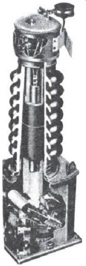
FIG. 13 Bushing-type CT ( Westinghouse Electric Corporation)
8. PRECAUTIONS IN USE OF CURRENT TRANSFORMER
8.1 Open Circuiting of CT Secondary
Current transformers are always used with its secondary circuit closed through very low resistance loads such as ammeters, wattmeter current coils, or relay coils. In such a case, a current transformer should never have its secondary terminals open circuited while the primary circuit is still energized.
One difference between a normal power transformer and a current transformer is that in a CT, the primary current is independent of the current flowing in the secondary, primary winding being connected in series with the main load, carries the line current. Thus, primary current is in no way controlled by the conditions of the secondary winding circuit of the CT.
Under normal operating conditions, the secondary current produces a so-called 'back mmf' that almost balances the primary winding ampere turns and restricts the flux in the core. This small mmf is responsible for producing flux in the core and supplies the iron losses. This resultant flux being small, the voltage induced in the secondary winding is also low.
If by any reason whatsoever, the secondary winding gets open circuited, then the secondary reverse mmf vanishes. The demagnetizing effect of the secondary mmf is now absent and the core carries the high flux created due to the primary ampere-turns only.
This large flux greatly increases flux density in the core and pushes it towards saturation.
This large flux, when links with the large number of secondary turns, produces a very high voltage, that could be damaging for the winding insulation as well as dangerous for the operator. The transformer insulation may get damaged under such high voltage stress.
In addition to this, increased hysteresis and eddy current losses at higher flux densities may overheat the transformer core.
Moreover, the high magnetizing forces acting on the core while secondary condition tend to magnetize the magnetic material to high values. If the open circuit condition is suddenly removed, the accuracy of the CT may be seriously impaired by the residual magnetism remaining in the core in case the primary circuit is broken or the secondary circuit is re-energized. This residual effect causes the transformer to operate at a different operating point on the magnetization curve, which affects the permeability and hence the calibration. This may lead to an altogether different values of ratio and phase-angle errors, obtained after such an open circuit, as compared to the corresponding values before it occurred. A transformer so treated, must first be demagnetized and then recalibrated before can be used reliably.
For these reasons, care must be taken to ensure that, even when not in use for measurement purposes, the secondary circuit is closed at any time when the primary circuit is energized. In those idle periods, the secondary circuit could (and should) be safely short circuited quite safely, since while being used for measurement it is practically short circuited by the ammeter, or wattmeter current coils, impedances of which are merely appreciable.
8.2 Permanent Magnetization of Core
Core material of a CT may undergo permanent magnetization due to one or more of the following reasons:
1. As discussed earlier, if by any chance the secondary winding is open circuited with the primary winding still energized, then the large flux will tend to magnetize the core to high values. If such a condition is abruptly removed, then there is a good possibility that a large residual magnetism will remain in the core.
2. A switching transient passing through the CT primary may leave behind appreciable amount of residual magnetism in the core.
3. Permanent magnetization may result from flow of dc current through either of the winding. The dc current may be flown through the winding for checking resistance or checking polarity.
4. Permanent magnetization may also result from transient short circuit current flowing through the line to which the CT is connected. Such transient currents are found to have dc components along with ac counterparts.
The presence of permanent magnetization in the core may alter the permeability of the material resulting in loss of calibration and increase in both ratio error and phase angle error. Thus, for reliable operation of the CT, the residual magnetism must be removed and the CT be restored back to its original condition. There are several methods of demagnetizing the core as described below:
1. One method is to pass a current through the primary winding equal to the current that was flowing during the period when the CT secondary was open circuited. The CT secondary circuit is left open. The voltage supply to the primary is then gradually reduced to zero. The CT core thus undergoes several cycles of gradually reducing magnetization till it finishes down to zero.
2. In the second method, the primary winding is supplied from a source so that rated current flows in the primary winding. A variable resistor of value certain hundred ohms is connected across the secondary winding. This simulates almost the CT secondary open circuit condition. The variable resistance is then gradually and uniformly reduced down to zero. In this way, the magnetization of the CT core gradually reduced down from its initial high value to normal original values.
9. POTENTIAL TRANSFORMERS (PT)
Measurement of voltage, power, etc., of high voltage lines requires the high level of voltage being stepped down before being applied to the measuring instrument. This is essential from the point of view of safety of operating personnel, reduction in size of instrument and saving in insulation cost. Potential transformers or PTs are used in such cases to operate voltmeters, potential coils of wattmeters, relays and other devices to be operated with high-voltage lines. The primary winding of the PT is connected across the high-voltage line whose voltage is to be measured and the measuring instruments are connected across the secondary of the PT. For all these purposes, it is essential that the secondary voltage be a definite fraction of the primary voltage, and in some applications they need to be in the same phase as well. Uses of PT for such applications are schematically shown in FIG. 14.
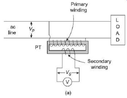
FIG. 14 Use of PT for (a) voltage, and (b) power measurement
There is essentially no difference in theory between a PT used for measurement purposes and a power transformer for regular use. The main differences between a PT and a power transformer are actually special requirements for the measurement system. These are the following:
1. Attenuation ratio must be accurately maintained in a PT since it is being used for measurement purposes.
2. Voltage drops in the windings must be minimized in a PT in order to reduce effects of phase shift and ratio error. Voltage drops in windings can be reduced by proper design to minimize leakage reactance and using large copper conductors.
3. Loading in a PT is always small, only of the order of few volt-amperes. Loading of a PT is actually limited by accuracy considerations; whereas in a power transformer, load limitation is on a heating basis.
4. Overload capacity for PTs are designed to be up to 2-3 times their normal rated values. Whereas, high capacity power transformers, under special circumstances, can take up overloads up to only 20% above their normal rating.
10. THEORY OF POTENTIAL TRANSFORMERS
FIG. 15 represent the equivalent circuit of a PT and FIG. 16 plots the phasor diagram under operating condition of the PT.
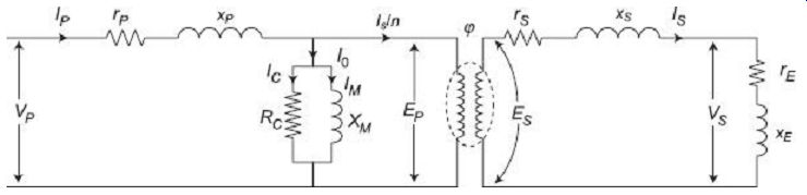
FIG. 15 Equivalent circuit of a PT
VP = primary supply voltage EP = primary winding induced voltage VS = secondary terminal voltage ES = secondary winding induced voltage IP = primary current IS = secondary current 10 = no-load current IC = core loss component of current IM = magnetizing component of current rP = resistance of primary winding xP = reactance of primary winding rS = resistance of secondary winding xS = reactance of secondary winding RC = imaginary resistance representing core losses XM = magnetizing reactance rE = resistance of external load (burden) including resistance of meters, current coils etc.
xE = reactance of external load (burden) including reactance of meters, current coils, etc.
NP = primary winding number of turns NS = secondary winding number of turns n = turns ratio = NP/NS f = working flux of the PT ? = the 'phase angle' of the PT d = phase angle between secondary winding terminal voltage and secondary winding current (i.e., phase angle of load circuit)
ß = phase angle between primary load current and secondary terminal voltage reversed a = phase angle between no-load current I0 and flux f
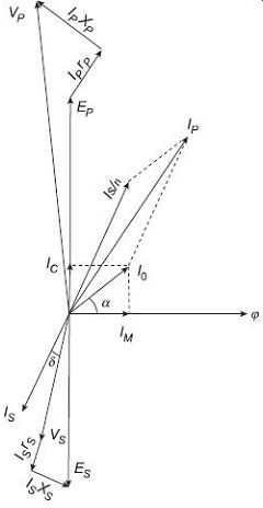
FIG. 16 Phasor diagram of a PT
The flux j is plotted along the positive x-axis. Magnetizing component of current Im is in phase with the flux. The core loss component of current IC, leads by IM90°. Summation of Ic and Im produces the no-load current I0.
The primary winding induced voltage EP is in the same phase with the resistive core loss component of current IC. As per transformer principles, the secondary winding induced voltage ES will be 180° out of phase with the primary winding induced voltage EP. Secondary output terminal voltage VS is obtained by vectorically subtracting the secondary winding resistive and reactive voltage drops IS rS and ISxS respectively from the secondary induced voltage ES.
Secondary voltages when referred to primary side need to be multiplied by the turns ratio n, whereas, when secondary currents are to be referred to primary side, they need to be divided by n. Secondary current IS, when reflected back to primary, can be represented by the 180° shifted phasor indicated by IS/n. Primary winding current Ip is the phasor summation of this reflected secondary current (load component) IS/n and the no-load current I0.
Vectorically adding the primary winding resistive and reactive voltage drops with the primary induced voltage will give the primary line voltage VP.
10.1 Voltage Transformation Ratio of PT
Redrawing the expanded view of the phasor diagram of FIG. 14, we obtain the phasor diagram of FIG. 17.
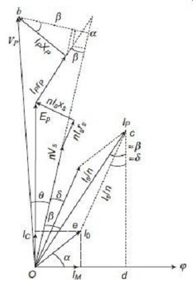
FIG. 17 Expanded view of a section of FIG. 16
11. ERRORS INTRODUCED BY POTENTIAL TRANSFORMERS
11.1 Ratio Error and Phase-Angle Error
It can be seen from the above section that, like current transformers, potential transformers also introduce errors in measurement. This error may be in terms of magnitude or phase, in the measured value of voltage. The ratio error (difference between nominal ratio and actual transformation ratio) only is important when measurements of voltage are to be made; the phase angle error is of importance only while measurement of power.
In presence of these errors, the voltage applied to the primary circuit of the PT can not be obtained accurately by simply multiplying the voltage measured by the voltmeter connected across the secondary by the turns ratio n of the PT.
These errors depend upon the resistance and reactance of the transformer winding as well as on the value of no-load current of the transformer.
11.2 Reducing Errors in PT
As discussed in the previous section, errors are introduced in the ratio and phase angle of a PT owing to the presence of the no-load component of the primary current and voltage drops across winding impedances. Improvement of accuracy, then, depends upon minimizing these components or nullifying in some way their effects in introducing errors.
This can be achieved by a combination of the following schemes:
1. Reducing the loss component and magnetizing components, i.e., the no-load component of the primary current can be achieved by reducing the length of magnetic path in the core, using good quality core magnetic materials, designing with appropriate value of flux densities in the core, and adopting precautionary measures while assembling and interleaving of core laminations.
2. Winding resistance can be reduced by using thick conductors and taking care to reduce the length of mean turn of the windings.
3. Winding leakage flux and hence leakage reactance can be reduced by keeping the primary and secondary windings as close as permissible from the point of view of insulation requirements.
4. Sufficiently high flux densities in the core will reduce the core cross-section, thereby reducing the length of winding wound over the core. This, in turn, will reduce the winding resistance. An optimization in the core flux density value to be used needs to done, since too high a flux density will increase the no-load current, which is also not desirable.
5. From ( 18) it is clear that at no load, the actual PT transformation ratio exceeds the turns ratio by an amount (IC rP+ IM XP)/VS. With increased loading, this difference grows due to further voltage drops in winding resistance and reactance. If the turns ratio can be set at a value less than the nominal ratio, then the difference between nominal ratio and actual transformation ratio under operating condition can be brought down. This can be achieved by reducing the number of turns in the primary winding or increasing the number of turns in the secondary winding. This makes it possible to make the actual transformation ratio to be equal to the nominal ratio, at least for a particular value and type of burden.
12. OPERATIONAL CHARACTERISTICS OF POTENTIAL TRANSFORMERS
Characteristics of potential transformers under different operating conditions may be estimated from the phasor diagram as shown in FIG. 20 and expressions for ratio error ( 19) and phase-angle error ( 22).
12.1 Effect of Change in Secondary Burden (VA or Current)
With increase in PT secondary burden, the secondary current is increased. This in turn will increase the primary current as well. Both primary and secondary voltage drops are increased and hence, for a given value of the primary supply voltage VP, secondary terminal voltage VS is reduced with increase of burden. The effect is therefore to increase the actual transformation ratio VP/VS with resulting increase in the ratio error as per Eq. (19). This increase in ratio error with increasing secondary burden is almost linear as shown in FIG. 18.
FIG. 18 Effects of secondary burden variation on (a) PT ratio error , and (b) PT phase angle error With regard to the phase angle, with increasing voltage drops due to increased burden, the phase difference between VP and VS reversed increases with resulting increase in phase angle error. Such a variation of phase-angle error with varying secondary burden in a typical potential transformer is shown in FIG. 18.
12.2 Effect of Change in Power Factor of Secondary Burden
As can be observed from the phasor diagram of potential transformer in FIG. 18, for all inductive burdens, the secondary winding current IS lags behind the secondary terminal voltage VS, so that the phase angle difference d is positive. At lower power factors, this phase angle difference d increases as IS moves further away from VS. Thus, from the phasor diagram, it is apparent that Ip will now become closer to I0. This will, in turn, move VP and VS more towards to be in phase with EP and ES respectively. It is to be kept in mind that change in power factor does not affect the magnitudes of resultant voltage drops in primary and secondary windings substantially. Under these conditions, with primary supply voltage VP being considered to remain the same, there is a reduction of EP relative to VP, and VS relative to ES. The actual transformation ratio VP /VS of the potential transformer will thus increase with reduction in burden power factor.
Further, since VS is advanced in phase and VP is retarded in phase, the phase angle of the transformer (between VS and VP) is reduced with reduction in burden (inductive) power factor.
FIG. 19 shows the variations of ratio and phase-angle errors in a typical current transformer at different values of the secondary burden power factor.
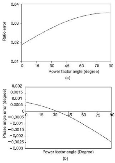
FIG. 19 Effects of secondary burden power factor variation on (a) PT
ratio error , and (b) PT phase angle error
13. DESIGN AND CONSTRUCTIONAL FEATURES OF POTENTIAL TRANSFORMERS
1. Core
The core construction of a PT may be of shell type or core type. Core-type construction is only used for low voltage applications. Special care is taken during interleaving and assembling of the core laminations so that minimal air gap is present in the stack joints.
2. Winding
The primary and secondary windings are made coaxial to restrict the leakage reactance to a minimum. In simplifying assembly and reducing insulation requirement, the low-voltage secondary winding is placed nearer to the core, with the high-voltage primary being wound over the secondary. For lower voltage rating the high-voltage primary winding can be made of a single coil, but for higher voltages, however, a number of separate coils can be assembled together to reduce insulation complicacies.
3. Insulation
Cotton tape and varnish is the most common insulation applied over windings during coil construction. At low voltages, PTs are usually filled with solid compounds, but at higher voltages above 7-10 kV, they are oil-immersed.
4. Bushings
Oil-filled bushings are normally used for oil filled potential transformers as this reduces the overall height. Some potential transformers connected between line and neutral of a grounded neutral system have only one bushing for the high voltage terminal. Some potential transformers can have two bushings when neither side of the line is at ground potential. A view of such a two-bushing potential transformer is shown in FIG. 20.
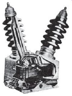
FIG. 20
Cutaway view of two-bushing type potential transformer (Westinghouse Electric
Corp.)
5. Cost and Size
Power transformers are designed keeping in view the efficiency, regulation and cost constraints. The cost in such cases is reduced by using smaller cores and conductor sizes.
In potential transformers, however, cost cannot be compromised with respect to desired performance and accuracy. Accuracy requirements in potential transformers in terms of ratio and phase angle obviate the use of good quality and amount of magnetic material for the core and also thick conductors for the winding.
6. Overload Capacity
Potential transformers are normally designed for very low power ratings and relatively large weight/ power ratio as compared to a power transformer. Theoretically, this can enable a potential transformer to run on appreciable overloads without causing much heating. Overload capacities of potential transformers are, however, limited by accuracy requirements, rather than heating.
14. DIFFERENCES BETWEEN CT AND PT
In summary, the following differences between a current transformer (CT) and a potential transformer (PT) can be tabulated:
QUIZ
Objective Questions
1. The disadvantages of using shunts for high current measurements are (a) power consumption by the shunts themselves is high (b) it is difficult to achieve good accuracy with shunts at high currents (c) the metering circuit is not electrically isolated from the power circuit (d) all of the above
2. The disadvantages of using multipliers with voltmeters for measuring high voltages are (a) power consumption by multipliers themselves is high at high voltages (b) multipliers at high voltage need to be shielded to prevent capacitive leakage (c) the metering circuit is not electrically isolated from the power circuit (d) all of the above
3. The advantages of instrument transformers are (a) the readings of instruments used along with instrument transformers rarely depend on the impedance of the instrument (b) due to availability of standardized instrument transformers and associated instruments, there is reduction in cost and ease of replacement (c) the metering circuit is electrically isolated from the power circuit (d) all of the above
4. Nominal ratio of a current transformer is (a) ratio of primary winding current to secondary winding current (b) ratio of rated primary winding current to rated secondary winding current (c) ratio of number of turns in the primary to number of turns in the secondary (d) all of the above
5. Burden of a CT is expressed in terms of (a) secondary winding current (b) VA rating of the transformer (c) power and power factor of the secondary winding circuit (d) impedance of secondary winding circuit
6. Ratio error in a CT is due to (a) secondary winding impedance (b) load impedance (c) no load current (d) all of the above
7. Phase-angle error in a CT is due to (a) primary winding impedance (b) primary circuit phase angle (c) leakage flux between primary and secondary (d) all of the above
8. Errors in instrument transformers can be aggravated by (a) leakage flux (b) core saturation (c) transients in main power line (d) all of the above
9. Phase-angle error in a CT can be reduced by (a) reducing number of secondary turns (b) using thin conductors for the primary winding (c) using good quality, low loss steel for core (d) all of the above
10. Ratio error in a CT can be reduced by (a) using good quality, low loss steel for core (b) placing primary and secondary windings closer to each other (c) using thick conductors for secondary winding (d) all of the above
11. Flux density in instrument transformers must be designed to be (a) sufficiently low to reduce core losses (b) sufficiently high to reduce core section and hence reduce length of winding (c) sufficiently low to prevent core saturation (d) properly optimized to have a balance among (a)-(c) 12. Current in the primary winding of CT depends on (a) burden in the secondary winding of the transformer (b) load connected to the system in which the CT is being used for measurement (c) both burden of the secondary and load connected to the system (d) none of the above
13. Turns compensation is used in CT to reduce (a) phase-angle error (b) both ratio and phase angle error (c) primarily ratio error, reduction in phase angle error is incidental (d) none of the above
14. Secondary winding of CT should never be open circuited with primary still energized because that will (a) increase power loss in the secondary winding (b) increase terminal voltage in the secondary winding (c) increase the leakage flux manifolds (d) all of the above
15. Open circuiting the secondary winding of CT with primary still energized will result in (a) unrestricted primary flux to generate high voltages across secondary terminals (b) possible insulation damage due to high voltage being generated (c) injury to careless operator (d) all of the above
2. Describe with clear schematic diagrams, how high voltage and currents are measured with the help of instrument transformers.
3. Draw and explain the nature of equivalent circuit the and corresponding phasor diagram of a current transformer.
4. Discuss the major sources of error in a current transformer.
5. Describe the design and constructional features of a current transformer for reducing ratio error and phase-angle error.
6. Explain with the help of a suitable example, the method of turns compensation in a CT to reduce ratio error.
7. Why should the secondary winding of a CT never be open circuited with its primary still energized?
8. Explain how the core of a CT may get permanent magnetization induced in it. What are the bad effects of such permanent magnetization? What are the ways to de-magnetize the core in such situations?
9. Draw and explain the constructional features of wound-type, bar type, clamp type and bushing type CTs.
10. Draw the equivalent circuit and phasor diagram of a potential transformer being used for measurement of high voltages.
11. What are the differences between a potential transformer and a regular power transformer?
12. Describe the methods employed for reducing ratio error and phase angle error in PTs.
More Questions
1. Draw and explain the nature of equivalent circuit and corresponding phasor diagram of a current transformer.
Derive expressions for the corresponding ratio error and phase angle error.
2. (a) What are the sources of error in a current transformer? (b) A ring-core type CT with nominal ratio 1000/5 and a bar primary has a secondary winding resistance of 0.8 Ohm and negligible reactance. The no load current is 4 A at a power factor of 0.35 when full load secondary current is flowing in a burden if 1.5 Ohm no-inductive resistance. Calculate the ratio error and phase-angle error at full load. Also calculate the flux in the core at 50 Hz.
3. (a) Describe the design and constructional features of a current transformer for reducing ratio error and phase angle error.
(b) A 1000/10 A, 50 Hz single-turn primary type CT has a secondary burden comprising of a pure resistance of 1.0 Ohm. Calculate flux in the core, ratio error and phase-angle error at full load. Neglect leakage reactance and assume the iron loss in the core to be 5 Ohm at full load. The magnetizing ampere-turns is 180.
4. (a) Why the secondary winding of a CT should never be open circuited with its primary still energized? (b) A bar-type CT has 300 turns in the secondary winding. The impedance of the secondary circuit is (1.5 + j2) Ohm.
With 5 A flowing in the secondary, the magnetizing mmf is 1000 A and the iron loss is Determine ratio and phase-angle errors.
5. (a) Explain the method of turns compensation in a CT to reduce ratio error.
(b) A bar-type CT has 400 turns in the secondary winding. An ammeter connected to the secondary has resistance of 1.5 Ohm and reactance of 1.0 Ohm, and the secondary winding impedance is (0.6 + j0.8) Ohm. The magnetizing mmf requirement for the core is 80 A and to supply the iron loss the current required is 30 A. (i) Find the primary winding current and also determine the ratio error when the ammeter in the secondary winding shows 4 A. (ii) How many turns should be reduced in the secondary to bring down ratio error to zero at this condition?
6. Draw and explain the nature of equivalent circuit and corresponding phasor diagram of a potential transformer.
Derive expressions for the corresponding ratio error and phase-angle error.
7. (a) What are the differences between a potential transformer and a regular power transformer? (b) A potential transformer with nominal ratio 1000/100 V has the following parameters:
Primary resistance = 96 Ohm
secondary resistance = 0.8 Ohm
Primary reactance = 80 Ohm
secondary reactance = 0.65 Ohm
No load current = 0.03 a at 0.35 power factor
Calculate (i) phase angle error at no load (ii) burden in VA at unity power factor at which phase angle error will be zero.
(a) Describe the methods employed for reducing ratio error and phase angle error in PTs?
(b) A potential transformer rated at 6000/100 V has 24000 turns in the primary and 400 turns in the secondary winding. With rated voltage applied to the primary and secondary circuit opened, the primary winding draws a current of 0.005 A lagging the voltage by 700. In another operating condition with a certain burden connected to the secondary, the primary draws 0.012 A at an angle 540 lagging with respect to the voltage.
The following parameters are given for the transformer:
Primary resistance = 600 Ohm
secondary resistance = 0.6 Ohm
Primary reactance = 1500 Ohm
secondary reactance = 0.96 Ohm
Calculate (i) Secondary load current and terminal voltage, using rated applied voltage as the reference (ii) The load burden in this condition (iii) Actual transformation ratio and phase angle (iv) How many turns should be changed in the primary winding to make the actual ratio equal to the nominal ratio under such operating condition?