AMAZON multi-meters discounts AMAZON oscilloscope discounts
1. INTRODUCTION
Resistors are used in many places in electrical circuits to perform a variety of useful tasks. Properties of resistances play an important role in determining performance specifications for various circuit elements including coils, windings, insulations, etc. It is important in many cases to have reasonably accurate information of the magnitude of resistance present in the circuit for analyzing its behavior. Measurement of resistance is thus one of the very basic requirements in many working circuits, machines, transformers, and meters. Apart from these applications, resistors are used as standards for the measurement of other unknown resistances and for the determination of unknown inductance and capacitance.
From the point of view of measurement, resistances can be classified as follows:
1. Low Resistances
All resistances of the order less than 1 O may be classified as low resistances. In practice, such resistances can be found in the copper winding in armatures, ammeter shunts, contacts, switches, etc.
2. Medium Resistances
Resistances in the range 1 O to 100 kO may be classified as medium resistances. Most of the electrical apparatus used in practice, electronic circuits, carbon resistance and metal film resistors are found to have resistance values lying in this range.
3. High Resistances
Resistances higher than 100 kO are classified as high resistances. Insulation resistances in electrical equipment are expected to have resistances above this range.
The above classifications are, however, not rigid, but only form a guideline for the method of measurement to be adopted, which may be different for different cases.
2. MEASUREMENT OF MEDIUM RESISTANCES
The different methods for measurement of medium range resistances are (i) ohmmeter method, (ii) voltmeter-ammeter method, (iii) substitution method, and (iv) Wheatstone bridge method.
2.1 Ohmmeter Method for Measuring Resistance
Ohmmeters are convenient direct reading devices for measurement of approximate resistance of circuit components without concerning too much about accuracy. This instrument is, however, very popular in the sense that it can give quick and direct readings for resistance values without any precise adjustments requirements from the operator. It is also useful in measurement laboratories as an adjunct to a precision bridge. Value of the unknown resistance to be measured is first obtained by the ohmmeter, and this can save lot of time in bridge balancing for obtaining the final precision value using the bridge.
Series-type Ohmmeter
FIG. 1 shows the elements of a simple single-range series-type ohmmeter.
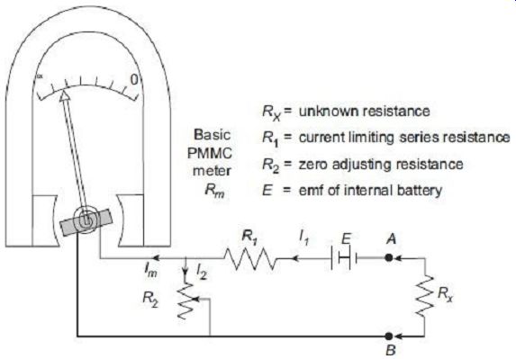
FIG. 1 Single-range series ohmmeter
The series-type ohmmeter consists basically of a sensitive dc measuring PMMC ammeter connected in parallel with a variable shunt R2. This parallel circuit is connected in series with a current limiting resistance R1 and a battery of emf E. The entire arrangement is connected to a pair of terminals (A-B) to which the unknown resistance Rx to be measured is connected.
Before actual readings are taken, the terminals A-B must be shorted together. At this position with Rx = 0, maximum current flows through the meter. The shunt resistance R2 is adjusted so that the meter deflects corresponding to its right most full scale deflection (FSD) position. The FSD position of the pointer is marked 'zero-resistance', i.e., 0 O on the scale. On the other hand, when the terminals A-B are kept open (Rx?8), no current flows through the meter and the pointer corresponds to the left most zero current position on the scale. This position of the pointer is marked as '8 O' on the scale. Thus, the meter will read infinite resistance at zero current position and zero resistance at full-scale current position. Series ohmmeters thus have '0' mark at the extreme right and '8' mark at the extreme left of scale (opposite to those for ammeters and voltmeters).
The main difficulty is the fact that ohmmeters are usually powered by batteries, and the battery voltage gradually changes with use and age. The shunt resistance R2 is used in such cases to counteract this effect and ensure proper zero setting at all times.
For zero setting, Rx = 0, where Rm = internal resistance of the basic PMMC meter coil The current I2 can be adjusted by varying R2 so that the meter current Im can be held at its calibrated value when the main current I1 changes due to drop in the battery emf E.
If R2 were not present, then it would also have been possible to bring the pointer to full scale by adjustment of the series resistance R1, But this would have changed the calibration all along the scale and cause large error.
(i) Design of R1 and R2
The extreme scale markings, i.e., 0 and 8, in an ohmmeter do not depend on the circuit constants. However, distributions of the scale markings between these two extremes are affected by the constants of the circuit. It is thus essential to design for proper values of the circuit constants, namely, R1 and R2 in particular to have proper calibration of the scale. The following parameters need to be known for determination of R1 and R2.
• Meter current Im at full scale deflection (= IFSD.)
• Meter coil resistance, Rm
• Ohmmeter battery voltage, E
• Value of the unknown resistance at half-scale deflection, (Rh), i.e., the value of Rx when the pointer is at the middle of scale
With terminals A-B shorted, when Rx = 0 Meter carries maximum current, and current flowing out of the battery is given as where Ri = internal resistance of the ohmmeter At half-scale deflection,
(ii) . Shape of Scale in Series Ohmmeters Electrical equivalent circuit of a series-type ohmmeter is shown in Figure 4.2.
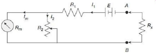
Fig. 2 Electrical equivalent circuit of a series-type ohmmeter
Internal resistance of the ohmmeter
From Eq. (5), it can be observed that the meter current Im is not related linearly with the resistance Rx to be measured. The scale (angle of deflection) in series ohmmeter if thus non-linear and cramped.
The above relation (5) also indicates the fact that the meter current and hence graduations of the scale get changed from the initial calibrated values each time the shunt resistance R2 is adjusted. A superior design is found in some ohmmeters where an adjustable soft-iron shunt is placed across the pole pieces of the meter, as indicated in FIG. 3.
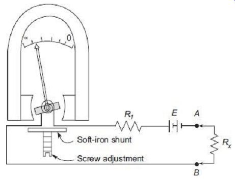
FIG. 3 Series ohmmeter with soft-iron magnetic shunt
The soft-iron magnetic shunt, when suitably positioned with the help of screw adjustment, modifies the air gap flux of main magnet, and hence controls sensitivity of movement. The pointer can thus be set at proper full scale marking in compensation against changes is battery emf, without any change in the electrical circuit. The scale calibrations thus do not get disturbed when the magnetic shunt is adjusted.
1. Multi-range Series Ohmmeter
For most practical purposes, it is necessary that a single ohmmeter be used for measurement of a wide range of resistance values. Using a single scale for such measurements will lead to inconvenience in meter readings and associated inaccuracies.
Multi-range ohmmeters, as shown schematically in FIG. 4, can be used for such measurements. The additional shunt resistances R3, R4…, R7 are used to adjust the meter current to correspond to 0 to FSD scale each time the range of the unknown resistance Rx is changed. In a practical multi-range ohmmeter, these shunt resistances are changed by rotating the range setting dial of the ohmmeter. The photograph of such a laboratory grade analog multi-range ohmmeter is provided in FIG. 5.
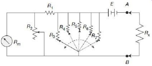
FIG. 4 Multi-range series-type ohmmeter
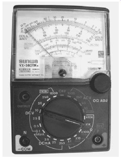
FIG. 5 Photograph of multi-range ohmmeter
2. Shunt-type Ohmmeter
FIG. 6 shows the schematic diagram of a simple shunt-type ohmmeter.
The shunt-type ohmmeter consists of a battery in series with an adjustable resistance R1 and a sensitive dc measuring PMMC ammeter. The unknown resistance Rx to be measured is connected across terminals A-B and parallel with the meter.
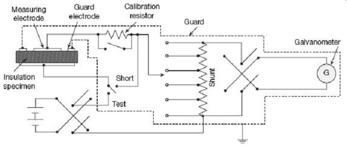
FIG. 6 Shunt-type ohmmeter
When the terminals A-B are shorted (Rx = 0), the meter current is zero, since all the current in the circuit passes through the short circuited path A-B, rather than the meter.
This position of the pointer is marked 'zero-resistance', i.e., '0 O' on the scale. On the other hand, when Rx is removed, i.e., the terminals A-B open circuited (Rx?8), entire current flows through the meter. Selecting proper value of R1, this maximum current position of the pointer can be made to read full scale of the meter. This position of the pointer is marked as '8O' on the scale. Shunt type ohmmeters, accordingly, has '0 O' at the left most position corresponding to zero current, and '8O' at the rightmost end of the scale corresponding to FSD current.
When not under measurement, i.e., nothing is connected across the terminals A-B (Rx ?8) the battery always drives FSD current through the meter. It is thus essential to disconnect the battery from rest of the circuit when the meter is idle. A switch S, as shown in FIG. 6, is thus needed to prevent the battery from draining out when the instrument is not in use.
2.2 Voltmeter-Ammeter Method for Measuring Resistance
The voltmeter-ammeter method is a direct application of ohm's law in which the unknown resistance is estimated by measurement of current (I) flowing through it and the voltage drop (V) across it. Then measured value of the resistance is This method is very simple and popular since the instruments required for measurement are usually easily available in the laboratory.
Two types of connections are employed for voltmeter-ammeter method as shown in FIG. 7.
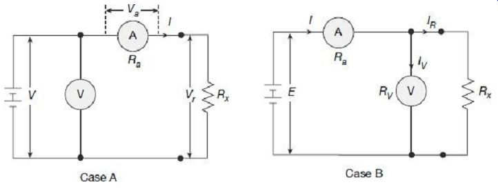
FIG. 7 Measurement of resistance by voltmeter-ammeter method
Rx = true value of unknown resistance Rm = measured value of unknown resistance Ra = internal resistance of ammeter RV = internal resistance of voltmeter It is desired that in both the cases shown in FIG. 7, the measured resistance Rm would be equal to the true value Rx of the unknown resistance. This is only possible, as we will see, if the ammeter resistance is zero and the voltmeter resistance is infinite.
Case A In this circuit, the ammeter is connected directly with the unknown resistance, but the voltmeter is connected across the series combination of ammeter and the resistance Rx.
The ammeter measures the true value of current through the resistance but the voltmeter does not measure the true value of voltage across the resistance. The voltmeter measures the sum of voltage drops across the ammeter and the unknown resistance Rx.
Let, voltmeter reading = V And, ammeter reading = I
measured value of resistance
However, V = Va + Vr or, V = I × Ra + I × Rx = I × (Ra + Rx)
Thus, ...
The measured value Rm of the unknown resistance is thus higher than the true value R, by the quantity Ra, internal resistance of the ammeter. It is also clear from the above that true value is equal to the measured value only if the ammeter resistance is zero.
Error in measurement is Equation (10) denotes the fact that error in measurement using connection method shown in Case A will be negligible only if the ratio . In other words, if the resistance under measurement is much higher as compared to the ammeter resistance (Rx Ra.), then the connection method shown in Case A can be employed without involving much error.
Therefore, circuit shown in Case A should be used for measurement of high resistance values.
Case B In this circuit, the voltmeter is connected directly across the unknown resistance, but the ammeter is connected in series with the parallel combination of voltmeter and the resistance Rx. The voltmeter thus measures the true value of voltage drop across the resistance but the ammeter does not measure the true value of current through the resistance. The ammeter measures the summation of current flowing through the voltmeter and the unknown resistance Rx.
2.3 Substitution Method for Measuring Resistance
The connection diagram for the substitution method is shown in FIG. 8.
In this method the unknown resistance Rx is measured with respect to the standard variable resistance S. The circuit also contains a steady voltage source V, a regulating resistance r and an ammeter. A switch is there to connect Rx and S in the circuit alternately.
To start with, the switch is connected in position 1, so that the unknown resistance Rx gets included in the circuit. At this condition, the regulating resistance r is adjusted so that the ammeter pointer comes to a specified location on the scale. Next, the switch is thrown to position 2, so that the standard resistance S comes into circuit in place of Rx. Settings in the regulating resistance are not changed. The standard variable resistance S is varied till ammeter pointer reaches the same location on scale as was with Rx. The value of the standard resistance S at this position is noted from its dial. Assuming that the battery emf has not changed and also since the value of r is kept same in both the cases, the current has been kept at the same value while substituting one resistance with another one. The two resistances thus, must be equal. Hence, value of the unknown resistance Rx can be estimated from dial settings of the standard resistance S.
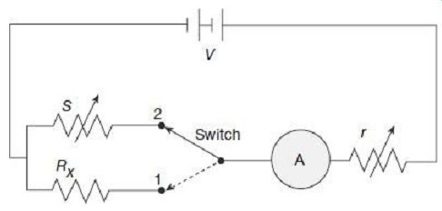
FIG. 8 Substitution method
Accuracy of this method depends on whether the battery emf remains constant between the two measurements. Also, other resistances in the circuit excepting R and S should also not change during the course of measurement. Readings must be taken fairly quickly so that temperature effects do not change circuit resistances appreciably. Measurement accuracy also depends on sensitivity of the ammeter and also on the accuracy of the standard resistance S.
2.4 Wheatstone Bridge for Measuring Resistance
The Wheatstone bridge is the most commonly used circuit for measurement of medium range resistances. The Wheatstone bridge consists of four resistance arms, together with a battery (voltage source) and a galvanometer (null detector). The circuit is shown in FIG. 9.
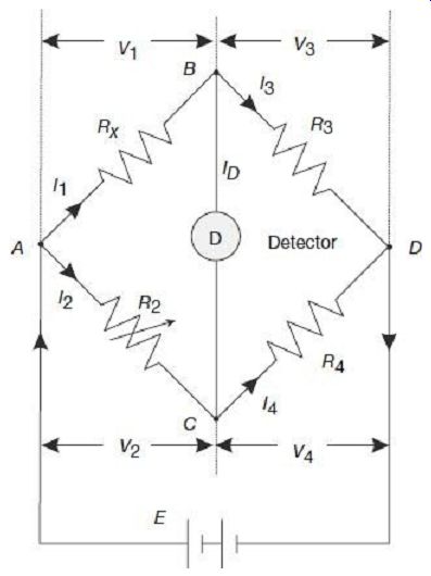
FIG. 9 Wheatstone bridge for measurement of resistance
In the bridge circuit, R3 and R4 are two fixed known resistances, R2 is a known variable resistance and RX is the unknown resistance to be measured. Under operating conditions, current ID through the galvanometer will depend on the difference in potential between nodes B and C. A bridge balance condition is achieved by varying the resistance R2 and checking whether the galvanometer pointer is resting at its zero position. At balance, no current flows through the galvanometer. This means that at balance, potentials at nodes B and C are equal. In other words, at balance the following conditions are satisfied:
1. The detector current is zero, i.e., 1D = 0 and thus
It = I3 and I2 = I4 2.
Potentials at node B and C are same, i.e., VB = VC, or in other words, voltage drop in the arm AB equals the voltage drop across the arm AC, i.e., VAB = VAC and voltage drop in the arm BD equals the voltage drop across the arm CD, i.e., VBD = VCD From the relation VAB = VAC we have I1 × Rx = I2 × R2 (12) At balanced 'null' position, since the galvanometer carries no current, it as if acts as if open circuited, thus
Thus, measurement of the unknown resistance is made in terms of three known resistances. The arms BD and CD containing the fixed resistances R3 and R4 are called the ratio arms. The arm AC containing the known variable resistance R2 is called the standard arm. The range of the resistance value that can be measured by the bridge can be increased simply by increasing the ratio R3/R4.
Errors in a Wheatstone Bridge
A Wheatstone bridge is a fairly convenient and accurate method for measuring resistance.
However, it is not free from errors as listed below:
1. Discrepancies between the true and marked values of resistances of the three known arms can introduce errors in measurement.
2. Inaccuracy of the balance point due to insufficient sensitivity of the galvanometer may result in false null points.
3. Bridge resistances may change due to self-heating (I 2R) resulting in error in measurement calculations.
4. Thermal emfs generated in the bridge circuit or in the galvanometer in the connection points may lead to error in measurement.
5. Errors may creep into measurement due to resistances of leads and contacts. This effect is however, negligible unless the unknown resistance is of very low value.
6. There may also be personal errors in finding the proper null point, taking readings, or during calculations.
Errors due to inaccuracies in values of standard resistors and insufficient sensitivity of galvanometer can be eliminated by using good quality resistors and galvanometer.
Temperature dependent change of resistance due to self-heating can be minimized by performing the measurement within as short time as possible.
Thermal emfs in the bridge arms may cause serious trouble, particularly while measuring low resistances. Thermal emf in galvanometer circuit may be serious in some cases, so care must be taken to minimize those effects for precision measurements. Some sensitive galvanometers employ all-copper systems (i.e., copper coils as well as copper suspensions), so that there is no junction of dissimilar metals to produce thermal emf. The effect of thermal emf can be balanced out in practice by adding a reversing switch in the circuit between the battery and the bridge, then making the bridge balance for each polarity and averaging the two results.
3. MEASUREMENT OF LOW RESISTANCES
The methods used for measurement of medium resistances are not suitable for measurement of low resistances. This is due to the fact that resistances of leads and contacts, though small, are appreciable in comparison to the low resistances under measurement. For example, a contact resistance of 0.001 O causes a negligible error when a medium resistance of value say, 100 O is being measured, but the same contact resistance would cause an error of 10% while measuring a low resistance of value 0. 01 O.
Hence special type of construction and techniques need to be used for measurement of low resistances to avoid errors due to leads and contacts. The different methods used for measurement of low range resistances are (i) voltmeter-ammeter method, (iii) Kelvin's double-bridge method, and (iv) potentiometer method.
3.1 Voltmeter-Ammeter Method for Measuring Low Resistance
In principle, the voltmeter-ammeter method for measurement of low resistance is very similar to the one used for measurement of medium resistances, as described in Section 2.2. This method, due to its simplicity, is very commonly used for measurement of low resistances when accuracy of the order of 1% is sufficient. The resistance elements, to be used for such measurements, however, need to of special construction. Low resistances are constructed with four terminals as shown in FIG. 10.
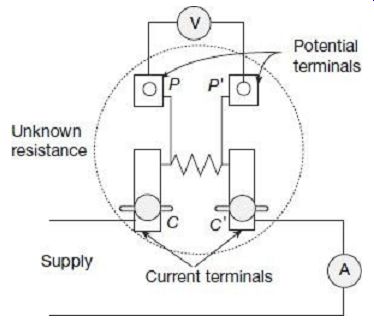
FIG. 10 Voltmeter-ammeter method for measuring
One pair of terminals CC', called the current terminals, is used to lead current to and from the resistor. The voltage drop across the resistance is measured between the other pair of terminals PP', called the potential terminals. The voltage indicated by the voltmeter is thus simply the voltage drop of the resistor across the potential terminals PP' and does not include any contact resistance drop that may be present at the current terminals CC'.
Contact drop at the potential terminals PP' are, however, less itself, since the currents passing through these contacts are extremely small (even zero under 'null' balance condition) owing to high resistance involved in the potential circuit. In addition to that, since the potential circuit has a high resistance voltmeter in it, any contact resistance drop in the potential terminals PP' will be negligible with respect to the high resistances involved in the potential circuit.
Value of the unknown resistance RX in this case is given by Precise measurement in this method requires that the voltmeter resistance to be appreciably high, otherwise the voltmeter current will be an appreciable fraction of the current actually flowing through the ammeter, and a serious error may be introduced in this account.
3.2 Kelvin's Double-Bridge Method for Measuring Low Resistance
Kelvin's double-bridge method is one of the best available methods for measurement of low resistances. It is actually a modification of the Wheatstone bridge in which the errors due to contacts and lead resistances can be eliminated. The connections of the bridge are shown in FIG. 11.
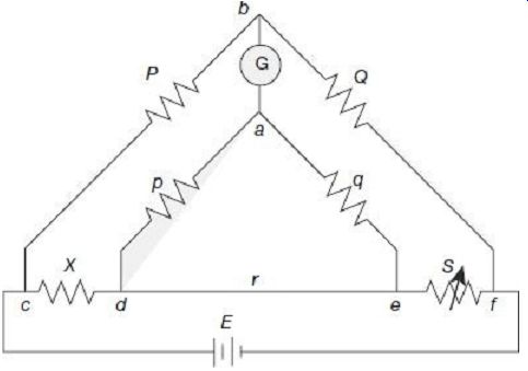
FIG. 11 Kelvin' s double bridge Kelvin's double bridge incorporates
the idea of a second set of ratio arms, namely, p and q, and hence the name
'double bridge'.
X is the unknown low resistance to be measured, and S is a known value standard low resistance. 'r' is a very low resistance connecting lead used connect the unknown resistance X to the standard resistance S. All other resistances P, Q, p, and q are of medium range. Balance in the bridge is achieved by adjusting S.
Under balanced condition, potentials at the nodes a and b must be equal in order that the galvanometer G gives "null" deflection. Since at balance, no current flows through the galvanometer, it can be considered to be open circuited and the circuit can be represented as shown in FIG. 12.
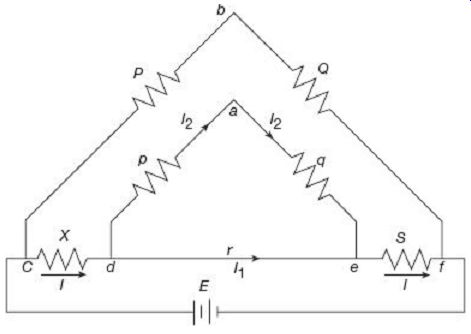
FIG. 12 Kelvin' s double-bridge under balanced condition Since under
balanced condition, potentials at the nodes a and b are equal, the we must
have ... the balance equation Vcb = Vcda can now be re-written as
3.3 Potentiometer Method for Measuring Low Resistance
The circuit for measurement of low value resistance with a potentiometer is shown in FIG. 13.
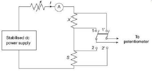
FIG. 13 Measurement of low resistance using potentiometer
The unknown resistance X is connected in series with a standard known resistance S.
Current through the ammeter in the circuit is controlled by a rheostat. A two-pole double throw switch is used. When the switch is in the position 1-1', the unknown resistance X gets connected to the potentiometer, whereas when the switch is at position 2-2', the standard resistance S gets connected to the potentiometer.
Potentiometers are believed to give reasonably accurate values of potentials.
Thus, with the switch in position 1-1', the potentiometer reading is the voltage drop across the unknown resistance, given by Without changing any of the circuit parameters, now if the switch is thrown to position 2-2', potentiometer now reads the voltage drop across the standard resistance, given by From Eqs (21) and (22), we get Knowledge of accurate value of the standard resistance S can thus give reasonably accurate values of the unknown resistance X.
Accuracy of this method however, depends on the assumption that the value of current remains absolutely constant during the two sets of measurements. Therefore, an extremely stabilized dc power supply is required in this method.
Value of the standard resistor S should be of the same order as the unknown resistance X. The ammeter inserted in the circuit has no other function rather than simply indicating whether there is any current is flowing in the circuit is not. Exact value of the current is not required for final calculations. It is however, desired that the current flowing through the circuit be so adjusted that the voltage drop across each resistor is of the order of 1 V to be suitable for accurate measurement by commercially available potentiometers.
4. MEASUREMENT OF HIGH RESISTANCES
High resistances of the order of several hundreds and thousands of megohms (MW) are often encountered in electrical equipments in the form of insulation resistance of machines and cables, leakage resistance of capacitors, volume and surface resistivity of different insulation materials and structures.
4.1 Difficulties in Measurement of High Resistance
1. Since the resistance under measurement has very high value, very small currents are encountered in the measurement circuit. Adequate precautions and care need to be taken to measure such low value currents.
2. Surface leakage is the main difficulty encountered while measurement of high resistances. The resistivity of the resistance under measurement may be high enough to impede flow of current through it, but due to moisture, dust, etc., the surface of the resistor may provide a lower resistance path for the current to pass between the two measuring electrodes. In other words, there may thus be a leakage through the surface. Leakage paths not only pollute the test results, but also are generally variable from day to day, depending on temperature and humidity conditions.
The effect of leakage paths on measurements can be eliminated by the use of guard circuits as described by FIG. 14.
FIG. 14(a) shows a high resistance RX being mounted on a piece of insulation block. A battery along with a voltmeter and a micro-ammeter are used to measure the resistance by voltmeter-ammeter method. The resistance RX under measurement is fitted on the insulating block at the two binding posts A and B. IX is the actual current flowing through the high resistance and IL is the surface leakage current flowing over the body of the insulating block. The micro-ammeter, in this case, thus reads the actual current through the resistor, and also the leakage current (I = IX + IL.).
Measured value of the resistance, thus computed from the ratio E/I, will not be the true value of RX, but will involve some error. To avoid this error, a guard arrangement has been added in FIG. 14(b). The guard arrangement, at one end is connected to the battery side of the micro-ammeter, and the other end is wrapped over the insulating body and surrounds the resistance terminal A. The surface leakage current now, flows through this guard and bypasses the micro-ammeter. The micro-ammeter thus reads the true of current IX through the resistance RX. This arrangement thus allows correct determination of the resistance value from the readings of voltmeter and micro-ammeter.
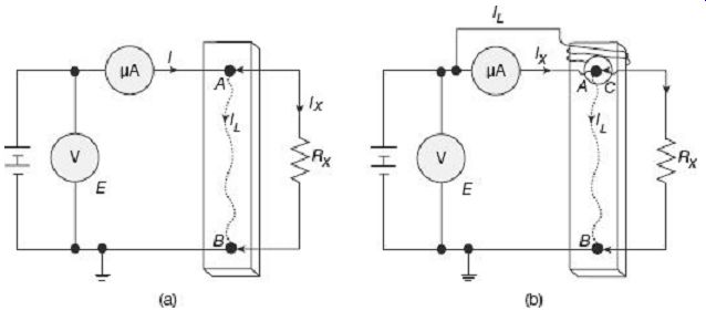
FIG. 14 Guard circuit for measurement of high resistance: (a) Circuit
without guard (b) Circuit with guard 3. Due to electrostatic effects, stray
charges may be induced in the measuring circuit.
Flow of these stray charges can constitute a current that can be comparable in magnitude with the low value current under measurement in high resistance circuits.
This may thus, cause errors in measurement. External alternating electromagnetic fields can also affect the measurement considerably. Therefore, the measuring circuit needs to be carefully screened to protect it against such external electrostatic or electromagnetic effects.
4. While measuring insulation resistance, the test object often has considerable amount of capacitance as well. On switching on the dc power supply, a large charging current may flow initially through the circuit, which gradually decays down. This initial transient current may introduce errors in measurement unless considerable time is provided between application of the voltage supply and reading the measurement, so that the charging current gets sufficient time to die down.
5. High resistance measurement results are also affected by changes in temperature, humidity and applied voltage inaccuracies.
6. Reasonably high voltages are used for measurement of high resistances in order to raise the current to substantial values in order to be measured, which are otherwise extremely low. So, the associated sensitive galvanometers and micro-ammeters need to be adequately protected against such high voltages.
Taking these factors into account, the most well-known methods of high resistance measurements are (i) direct deflection method, (ii) loss of charge method, and (iii) megohmmeter or meggar.
4.2 Direct Deflection Method for High Resistance Measurement
The direct deflection method for measuring high resistances is based on the circuit described in FIG. 14, which in effect is the voltmeter-ammeter method. For measurement of high resistances, a sensitive galvanometer is used instead of a micro ammeter as shown in FIG. 14. A schematic diagram for describing the direct deflection method for measurement of insulation resistance of a metal sheathed cable is given in FIG. 15.
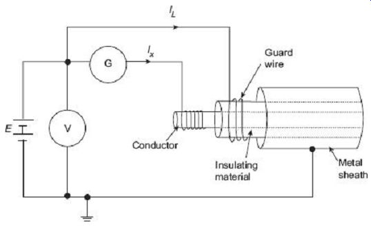
FIG. 15 Measurement of cable insulation resistance
The test specimen, cable in this case, is connected across a high voltage stable dc source; one end of the source being connected to the inner conductor of the cable, and the other end, to the outer metal sheath of the cable. The galvanometer G, connected in series as shown in FIG. 15, is intended to measure the current IX flowing through the volume of the insulation between the central conductor and the outer metal sheath. Any leakage current IL flowing over the surface of the insulating material is bypassed through a guard wire wound on the insulation, and therefore does not flow through the galvanometer.
A more detailed scheme for measurement of insulation resistance of a specimen sheet of solid insulation is shown in FIG. 16.
FIG. 16 Measurement of high resistance by direct deflection method
A metal disk covering almost the entire surface is used as electrode on one side of the insulation sheet under measurement. On the other side of the insulating sheet, the second electrode is made of a smaller size disk. A guard ring is placed around the second electrode with a small spacing in between them. This guarding arrangement bypasses any surface leakage current on the insulator or any other parts of the circuit from entering the actual measuring circuit. The galvanometer thus reads specifically the volume resistance of the insulation specimen, independent of any surface leakage.
A calibrated Ayrton shunt is usually included along with the galvanometer to provide various scale ranges and also to protect it.
The galvanometer scale is graduated directly in terms of resistance. After one set of measurement is over, the galvanometer is calibrated with the help of a high value (˜ 1 MO) calibrating resistor and the shunts.
In case the insulation under measurement has high inherent capacitance values (like in a cable), there will be an initial inrush of high capacitive charging current when the dc source is first switched on. This charging current will, however, decay down to a steady dc value with time. To protect the galvanometer from such initial rush of high current, the Ayrton shunt connected across the galvanometer should be placed at the highest resistance position (lower most point in FIG. 16). Thus, initially the galvanometer is bypassed from the high charging current.
After the test is complete, it is required that the test specimen should be discharged, especially if it is of capacitive in nature. The 'test-short' switch is placed in the 'short' position so that any charge remaining in the insulation specimen is discharged through the short circuited path.
The change-over switch across the battery enables tests at different polarities. The switch across the galvanometer enables reversal of the galvanometer connections.
A special technique, Price's guard-wire method is employed for measurement of insulation resistance of cables which do not have metal sheath outside. The schematic diagram of such a measurement system is provided in FIG. 17.
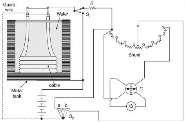
FIG. 17 Measurement of high resistance by Price' s guard-wire method
The unsheathed cable, except at the two ends where connections are made, is immersed in water in a tank. For testing of the cable insulation, the cable core conductor acts as one electrode and in the absence of the metal sheath outside, the water and the tank act as the other electrode for measurement. The cable is immersed in slightly saline water for about a day and at nearly constant ambient temperature.
The two ends of the cables are trimmed as shown in FIG. 17, thus exposing the core conductor as well as some portion of the insulation. The core conductors are connected together to form one electrode of the measuring system. A guard circuit is formed by twisting a bare wire around the exposed portion of the insulation at the two stripped ends of the cable. This guard wire is connected to the negative terminal of the supply battery.
The positive terminal of the battery is connected to the metal tank. This enables any surface leakage current to bypass the galvanometer and pass directly to the battery. Thus, the galvanometer will read only true value of the current flowing through volume of the insulation, and not the additional surface leakage current.
The D'Arsonval galvanometer to be used is normally of very high resistance and very sensitive to record the normally extremely low insulation currents. An Ayrton universal shunt is usually included along with the galvanometer to provide various scale ranges and also to protect it. The galvanometer scale is graduated directly in terms of resistance. After one set of measurement is over, the galvanometer is calibrated with the help of the high value (˜ 1 MO) calibrating resistor R and the shunt. The resistance R and the shunt also serve the purpose of protecting the galvanometer from accidental short circuit current surges. The 4-terminal commutator C, as shown in FIG. 17 is used for reversal of galvanometer connections.
Since the cable will invariably have high capacitance value, there will be an initial inrush of high capacitive charging current when the dc source is first switched on. This charging current will, however, decay down to a steady dc value with time. To protect the galvanometer from such initial rush of high current, the switch S2 is placed on position a so that initially the galvanometer is bypassed from the high charging current. Once the capacitor charging period is over and the current settles down, the switch S2 is pushed over to position b to bring the galvanometer back in the measurement circuit. The contacts a and b are sufficiently close enough to prevent the circuit from breaking while the switch S2 is moved over.
After the test is complete, it is required that the test specimen should be discharged. The switch S1 is used for this purpose, so that any charge remaining in the insulation specimen is discharged through itself.
4.3 Loss of Charge Method for High Resistance Measurement
In this method, the resistance to be measured is connected directly across a dc voltage source in parallel with a capacitor. The capacitor is charged up to a certain voltage and then discharged through the resistance to be measured. The terminal voltage across the resistance-capacitance parallel combination is recorded for a pre-defined period of time with a help of a high-resistance voltmeter (electrostatic voltmeter or digital electrometers).
Value of the unknown resistance is calculated from the discharge time constant of the circuit. Operation of the loss of charge method can be described by the schematic circuit diagram of FIG. 18.
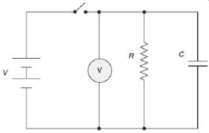
FIG. 18 Loss of charge method for measurement of high resistance In
FIG. 18, the unknown resistance R to be measured is connected across
the capacitor C and their parallel combination is connected to the dc voltage
source.
Let the capacitor is initially charged up to a voltage of V while the switch is kept ON.
Once the switch is turned OFF, the capacitor starts to discharge through the resistance R.
During the discharge process, the voltage v across the capacitor at any instant of time t is given by Thus, the insulation resistance can be calculated as With known value of C and recorded values of t, V and v, the unknown resistance R can be estimated using (24).
The pattern of variation of voltage v with time is shown in FIG. 19.
FIG. 19 Capacitor discharge pattern Great care must be taken to record the voltages V and v and also the time t very precisely, otherwise large errors may creep in to the calculation results.
This method, though simple in principle, require careful choice of the capacitor. The capacitor C itself must have sufficiently high value of its own leakage resistance, at least in the same range as the unknown resistance under measurement. The resistance of the voltmeter also needs to be very high to have more accurate results.
4.4 Megohmmeter, or Meggar, for High Resistance Measurement
One of the most popular portable type insulation resistance measuring instruments is the megohmmeter or in short, meggar. The meggar is used very commonly for measurement of insulation resistance of electrical machines, insulators, bushings, etc. Internal diagram of a meggar is shown in FIG. 20.
The traditional analog deflecting-type meggar is essentially a permanent magnet crossed-coil shunt type ohmmeter.
The instrument has a small permanent magnet dc generator developing 500 V dc (some other models also have 100 V, 250 V, 1000 or 2500 V generators). The generator is hand driven, through gear arrangements, and through a centrifugally controlled clutch switch which slips at a predefined speed so that a constant voltage can be developed. Some meggars also have rectified ac as power supply.
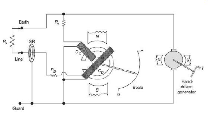
FIG. 20 Meggar for high resistance measurement
The moving system in such instruments consists of two coils, the control coil CC and the deflecting coil CD. Both the coils are mounted rigidly on a shaft that carries the pointer as well. The two coils move in the air gap of a permanent magnet. The two coils are arranged with such numbers of turns, radii of action, and connected across the generator with such polarities that, for external magnetic fields of uniform intensity, the torque produced by the individual coils are in opposition thus giving an astatic combination. The deflecting coil is connected in series with the unknown resistance RX under measurement, a fixed resistor RD and then the generator. The current coil or the compensating coil, along with the fixed resistance RC is connected directly across the generator. For any value of the unknown, the coils and the pointer take up a final steady position such that the torques of the two coils are equal and balanced against each other. For example, when the resistance RX under measurement is removed, i.e., the test terminals are open-circuited, no current flows through the deflecting coil CD, but maximum current will flow through the control coil CC. The control coil CC thus sets itself perpendicular to the magnetic axis with the pointer indicating '8 O' as marked in the scale shown in FIG. 20. As the value of RX is brought down from open circuit condition, more and more current flows through the deflecting coil CD, and the pointer moves away from the '8 O' mark clockwise (according to FIG. 20) on the scale, and ultimately reaches the '0 O' mark when the two test terminals are short circuited.
The surface leakage problem is taken care of by the guard-wire arrangement. The guard ring (GR in FIG. 20) and the guard wire diverts the surface leakage current from reaching the main moving system and interfering with its performance.
Photographs of some commercially available meggars are shown in FIG. 21.
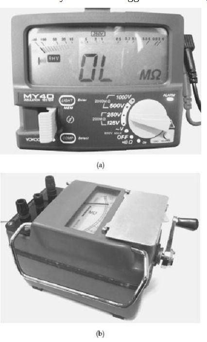
FIG. 21 Commercial meggars: (a) Analog type ( WACO) (b) Digital type
(Yokogawa)
5. LOCALIZATION OF CABLE FAULTS
Underground cables during their operation can experience various fault conditions. Whereas routine standard tests are there to identify and locate faults in high-voltage cables, special procedures, as will be described in this section are required for localization of cable faults in low distribution voltage level cables. Determination of exact location of fault sections in underground distribution cables is extremely important from the point of view of quick restoration of service without loss of time for repair.
The faults that are most likely to occur are ground faults where cable insulation may break down causing a current to flow from the core of the cable to the outer metal sheath or to the earth; or there may be short-circuit faults where a insulation failure between two cables, or between two cores of a multi-core cable results in flow of current between them.
Loop tests are popularly used in localization of the aforesaid types of faults in low voltage cables. These tests can be carried out to localize a ground fault or a short-circuit fault, provided that an unfaulty cable runs along with the faulty cable. Such tests have the advantage that fault resistance does not affect the measurement sensitivity, that the fault resistance is not too high. Loop tests work on the simple principles of a Wheatstone bridge for measurement of unknown resistances.
5.1 Murray Loop Test
Connections for this test are shown in FIG. 22. FIG. 22(a) shows the connection diagram for localization of ground faults and FIG. 22(b) relates to localization of short circuit faults. The general configuration of a Wheatstone bridge is given in FIG. 23 for ready reference.
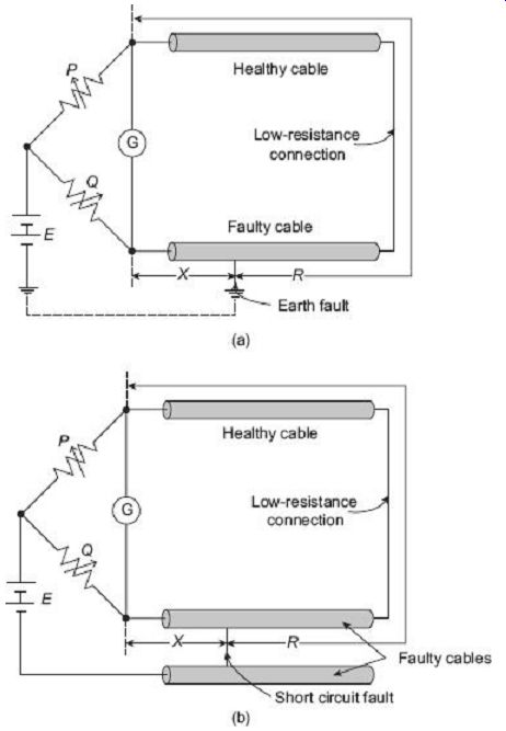
FIG. 22 Murray loop test for (a) earth fault, and (b) short-circuit
fault localization in cables The loop circuits formed by the cable conductors
form a Wheatstone bridge circuit with the two externally controllable resistors
P and Q and the cable resistance X and R as shown in FIG. 22. The galvanometer
G is used for balance detection. The ridge is balanced by adjustment of P
and Q till the galvanometer indicates zero deflection.
FIG. 23 Wheatstone bridge configuration relating to FIG. 22 Under balanced condition.
Here, (R + X) is the total loop resistance formed by the good cable and the faulty cable.
When the cables have the same cross section and same resistivity, their resistances are proportional to their lengths.
If LX represents the distance of the fault point from the test end, and L is the total length of each cable under test, then we can write 1. The resistance X is proportional to the length LX 2. The resistance (R + X) is proportional to the total length 2L Equation (25) can now be expressed in terms of the lengths as Thus, position of the fault can easily be located when the total length of the cables are known.
5.2 Varley Loop Test
In this test, the total loop resistance involving the cables is determined experimentally to estimate the fault location, rather than relying upon the information of length of cables and their resistances per unit length. Connections diagrams for Varley loop test to detect ground fault location and short-circuit fault location in low voltage cables is shown in FIG. 24 (a) and FIG. 24 (b) respectively.
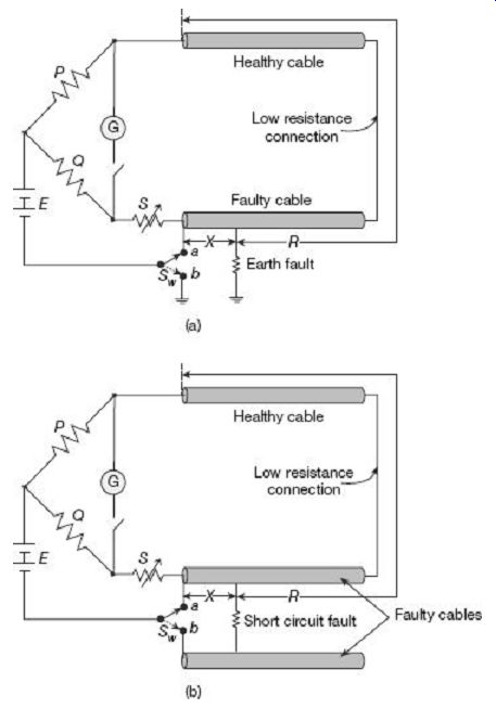
FIG. 24 Varley loop test for (a) earth fault, and (b) short-circuit
fault localization in cables
The single pole double throw switch Sw is first connected to terminal 'a' and the resistance S is varied to obtain bridge balance.
Let, at this condition, the value of resistance S = S1 when the bridge is balanced. Thus, from Wheatstone bridge principles, at balance condition with the switch at position a, we can write The total loop resistance (R + X) can thus be experimentally determined using (27) by reading the values of P, Q and S1 under bridge balanced condition with the switch at position a.
Now, the switch Sw is changed over to terminal b and the bridge is balanced again by varying S. Let, at this condition, the value of resistance S = S2 when the bridge is balanced. Thus, once again, from Wheatstone bridge principles, at balance condition with the switch at position b, we can write
Thus, X can be calculated from (28) from known values of P, Q, and S2 and the value of total loop resistance (R + X) obtained from (27).
If LX represents the distance of the fault point from the test end, and L is the total length of each cable under test, then we can write:
1. the resistance X is proportional to the length LX 2. the resistance (R + X) is proportional to the total length 2L Then we can write Thus, the position of the fault can easily be located when the total length of the cables are known.
Both Murray and Varley loop tests are valid only when the cable cross sections are uniform throughout the loop and also between the healthy and faulty cables. Correction factors need also to be included to take care of temperature variation effects. Too many cable joints within length of the cables may also introduce errors in measurement.
Objective Questions
1. In a series-type ohmmeter (a) zero marking is on the left-hand side (b) zero marking is at the centre (c) zero marking is on the right-hand side (d) zero marking may be either on left or right-hand side
2. In series type ohmmeters, zero adjustment should be done by (a) changing the shunt resistance across the meter movement (b) changing the series resistance (c) changing the series and the shunt resistance (d) changing the battery voltage
3. Screw adjustments are preferred over shunt resistance adjustments for zero calibration in ohmmeters because (a) the former method is less costly (b) the former method does not disturb the scale calibration (c) the former method does not disturb the meter magnetic field (d) all of the above
4. The shape of scale in an analog series-type ohmmeter is (a) linearly spaced (b) cramped near the start (c) cramped near the end (d) directly proportional to the resistance
5. Shunt-type ohmmeters have on their scale (a) zero ohm marking on the right corresponding to zero current (b) zero ohm marking on the right corresponding to full scale current (c) infinite ohm marking on the right corresponding to zero current (d) infinite ohm marking on the right corresponding to full scale current
6. Shunt-type ohmmeters have a switch along with the battery to (a) disconnect the battery when not in use (b) prevent meter from getting damaged when measuring very low resistances (c) compensate for thermo-emf effects by reversing battery polarity (d) all of the above
7. The shape of scale in an analog shunt-type ohmmeter is (a) linearly spaced at lower scales (b) cramped near the start (c) linearly spaced at higher scales (d) uniform all throughout the scale
8. High resistances using the voltmeter-ammeter method should be measured with (a) voltmeter connected to the source side (b) ammeter connected to the source side (c) any of the two connections (d) readings are to be taken by interchanging ammeter and voltmeter positions
9. Low resistances using the voltmeter-ammeter method should be measured with (a) voltmeter connected to the source side (b) ammeter connected to the source side (c) any of the two connections (d) readings are to be taken by interchanging ammeter and voltmeter positions
10. Accuracy of the substitution method for measurement of unknown resistance depends on (a) accuracy of the ammeter (b) accuracy of the standard resistance to which the unknown is compared (c) accuracy in taking the readings (d) all of the above
11. The null detector used in a Wheatstone bridge is basically a (a) sensitive voltmeter (b) sensitive ammeter (c) may be any of the above (d) none of (a) or (b)
12. Wheatstone bridge is not preferred for precision measurements because of errors due to (a) resistance of connecting leads (b) resistance of contacts (c) thermo-electric emf (d) all of the above
13. Error due to thermo-electric emf effects in a Wheatstone bridge can be eliminated by (a) taking the readings as quickly as possible (b) by avoiding junctions with dissimilar metals (c) by using a reversing switch to change battery polarity (d) all of the above
14. Low resistances are measured with four terminals to (a) eliminate effects of leads (b) enable the resistance value to be independent of the nature of contact at the current terminals (c) to facilitate connections to current and potential coils of the meters (d) all of the above
15. Kelvin's double bridge is called 'double' because (a) it has double the accuracy of a Wheatstone bridge (b) its maximum scale range is double that of a Wheatstone bridge (c) it can measure two unknown resistances simultaneously, i.e., double the capacity of a Wheatstone bridge (d) it has two additional ratio arms, i.e., double the number of ratio arms as compared to a Wheatstone bridge
16. Two sets of readings are taken in a Kelvin's double bridge with the battery polarity reversed in order to (a) eliminate the error due to contact resistance (b) eliminate the error due to thermo-electric effect (c) eliminate the error due to change in battery voltage (d) all of the above
17. Potentiometers, when used for measurement of unknown resistances, give more accurate results as compared to the voltmeter-ammeter method because (a) there is no error due to thermo-electric effect in potentiometers (b) the accuracy of voltage measurement is higher in potentiometers (c) personnel errors while reading a potentiometer is comparatively less (d) all of the above
18. 'Null detection method' is more accurate than 'deflection method' for measurement of unknown resistances because (a) the former does not include errors due to nonlinear scale of the meters (b) the former does not include errors due to change in battery voltage
(c) the former does to depend on meter sensitivity at balanced condition (d) all of the above
19. Guard terminals are recommended for high resistance measurements to (a) bypass the leakage current (b) guard the resistance from effects of stray electro-magnetic fields (c) guard the resistance from effects of stray electro-static fields (d) none of the above
20. When measuring cable insulation using a dc source, the galvanometer used is initially short circuited to (a) discharge the stored charge in the cable (b) bypass the high initial charging current (c) prevent the galvanometer from getting damaged due to low resistance of the cable (d) all of the above
21. The loss of charge method is used for measurement of (a) high value capacitances (b) dissipation factor of capacitances (c) low value resistances (d) high value resistances
22. A meggar is used for measurement of (a) low value resistances (b) medium value resistances (c) high value, particularly insulation resistances (d) all of the above
23. Controlling torque in a meggar is provided by (a) control springs (b) balance weights (c) control coil (d) any one of the above
24. The advantage of Varley loop test over Murray loop test for cable fault localization is (a) the former can be used for localizing faults even without knowledge of cable resistance (b) the former can be used for localizing both earth fault and short circuit faults (c) the former can experimentally determine the total loop resistance (d) all of the above
25. Possible sources of error in using loop test for cable fault localization are (a) uneven cable resistance/km (b) temperature variations (c) unknown cable joint resistances (d) all of the above
Questions
1. Describe the operation of a series-type ohmmeter with the help of a schematic diagram. Comment on the scale markings and zero adjustment procedures in such an instrument.
2. Derive an expression for the meter current as a function of the full-scale deflection value in a series type ohmmeter to determine the shape of scale.
3. Describe the operation of a shunt-type ohmmeter with the help of a schematic diagram. Comment on the scale markings and zero adjustment procedures in such an instrument.
4. Derive an expression for the meter current as a function of the full-scale deflection value in a shunt type ohmmeter to determine the shape of scale.
5. List the sources of errors in a Wheatstone bridge that may affect its precision while measuring medium range resistances. Explain how these effects are eliminated/minimized?
6. What are the different problems encountered while measuring low resistances. Explain how a 4-terminal configuration can minimize these errors while measuring low resistances using a voltmeter-ammeter method.
7. Describe how low resistances can be measured with the help of a potentiometer.
8. Describe with suitable schematic diagram, how a high resistance can be effectively measured using Price's guard wire method.
9. Explain the principles of the loss of charge method for measurement of high resistances. Also comment on the compensations required to be made in the calculations to take care of circuit component non-idealities.
10. Draw and explain the operation of a meggar used for high resistance measurement.
11. Describe with suitable schematic diagram, the Murray Loop test for localizing earth fault in low voltage cables.
12. Describe with suitable schematic diagram, the Varley loop test for localizing earth fault in low voltage cables.
More Questions
1. (a) Discuss with suitable diagrams, the different ways of zero adjustment in a series-type ohmmeter.
(b) Design a single range series-type ohmmeter using a PMMC ammeter that has internal resistance of 60 O and requires a current of 1.2 mA for full scale deflection. The internal battery has a voltage of 5 V. It is desired to read half scale at a resistance value of 3000 O. Calculate (a) the values of shunt resistance and current limiting series resistance, and (b) range of values of the shunt resistance to accommodate battery voltage variation in the range 4.7 to 5.2 V.
2. (a) Describe the operation of a shunt-type ohmmeter with the help of a schematic diagram. Comment son the scale markings and zero adjustment procedures in such an instrument? (b) A shunt-type ohmmeter uses a 2 mA basic d'Arsonval movement with an internal resistance of 50 O. The battery emf is 3 V. Calculate (a) value of the resistor in series with the battery to adjust the FSD, and (b) at what point (percentage) of full scale will 200 O be marked on the scale? 3. (a) Describe in brief, the use of voltmeter-ammeter method for measurement of unknown resistance.
(b) A voltmeter of 500 O resistance and a milliammeter of 0.5 O resistance are used to measure two unknown resistances by voltmeter-ammeter method. If the voltmeter reads 50 V and milliammeter reads 50 mA in both the cases, calculate the percentage error in the values of measured resistances if (i) in the first case, the voltmeter is put across the resistance and the milliammeter connected in series with the supply, and (ii) in the second case, the voltmeter is connected in the supply, side and milliammeter connected directly in series with the resistance.
4. (a) Draw the circuit of a Wheatstone bridge for measurement of unknown resistances and derive the condition for balance.
(b) Four arms of a Wheatstone bridge are as follows: AB = 150 W, BC = 15 W, CD = 6 W, DA = 60 O. A galvanometer with internal resistance of 25 O is connected between BD, while a battery of 20 V dc is connected between AC. Find the current through the galvanometer. Find the value of the resistance to be put on the arm DA so that the bridge is balanced.
5. (a) Explain the principle of working of a Kelvin's double bridge for measurement of unknown low resistances. Explain how the effects of contact resistance and resistance of leads are eliminated.
(b) A 4-terminal resistor was measured with the help of a Kelvin's double bridge having the following components: Standard resistor = 100.02 |iW, inner ratio arms = 100.022 O and 199 W, outer ratio arms = 100.025 O and 200.46 W, resistance of the link connecting the standard resistance and the unknown resistance = 300 mW. Calculate value of the unknown resistance.
6. Discuss the difficulties involved for measurement of high resistances. Explain the purpose of guarding a high resistance measurement circuits.
7. (a) Derive an expression for the unknown resistance measured using the loss of charge method.
(b) A cable is tested for insulation resistance by loss of charge method. An electrostatic voltmeter is connected between the cable conductor and earth. This combination is found to form a capacitance of 600 pF between the conductor and earth. It is observed that after charging the cable with 1000 V for sufficiently long time, when the voltage supply is withdrawn, the voltage drops down to 480 V in 1 minute. Calculate the insulation resistance of the cable.
8. (a) Describe with suitable schematic diagrams, the Murray loop test for localization of earth fault and short circuit fault in low voltage cables.
(b) n a test for fault to earth by Murray loop test, the faulty cable has a length of 6.8 km. The faulty cable is looped with a sound (healthy) cable of the same length and cross section. Resistances of the ratio arm of the measuring bridge circuit are 200 O and 444 O at balance. Calculate the distance of the fault point from the testing terminal.
9. (a) Describe with suitable schematic diagrams, the Varley loop test for localization of earth fault and short-circuit fault in low voltage cables.
(b) Varley loop test is being used to locate short circuit fault. The faulty and sound cables are identical with resistances of 0.4 O per km. The ratio arms are set at 20 O and 50 O. Values of the variable resistance connected with the faulty cable are 30 O and 15 O at the two positions of the selector switch. Determine the length of each cable and fault distance from test end.