AMAZON multi-meters discounts AMAZON oscilloscope discounts
1. INTRODUCTION
A potentiometer is an instrument which is used for measurement of potential difference across a known resistance or between two terminals of a circuit or network of known characteristics. A potentiometer is also used for comparing the emf of two cells. A potentiometer is extensively used in measurements where the precision required is higher than that can be obtained by ordinary deflecting instruments, or where it is required that no current be drawn from the source under test, or where the current must be limited to a small value.
Since a potentiometer measures voltage by comparing it with a standard cell, it can be also used to measure the current simply by measuring the voltage drop produced by the unknown current passing through a known standard resistance. By the potentiometer, power can also be calculated and if the time is also measured, energy can be determined by simply multiplying the power and time of measurement. Thus potentiometer is one of the most fundamental instruments of electrical measurement.
Some important characteristics of potentiometer are the following:
• A potentiometer measures the unknown voltage by comparing it with a known voltage source rather than by the actual deflection of the pointer. This ensures a high degree of accuracy.
• As a potentiometer measures using null or balance condition, hence no power is required for the measurement.
• Determination of voltage using potentiometer is quite independent of the source resistance.
2. A BASIC dc POTENTIOMETER
The circuit diagram of a basic dc potentiometer is shown in FIG. 1.
Operation
First, the switch S is put in the 'operate' position and the galvanometer key K kept open, the battery supplies the working current through the rheostat and the slide wire. The working current through the slide wire may be varied by changing the rheostat setting. The method of measuring the unknown voltage, E1, depends upon the finding a position for the sliding contact such that the galvanometer shows zero deflection, i.e., indicates null condition, when the galvanometer key K is closed. Zero galvanometer deflection means that the unknown voltage E1 is equal to the voltage drop E2, across position a-c of the slide wire. Thus, determination of the values of unknown voltage now becomes a matter of evaluating the voltage drop E2 along the portion a-c of the slide wire.
When the switch S is placed at ' calibrate' position, a standard or reference cell is connected to the circuit. This reference cell is used to standardize the potentiometer. The slide wire has a uniform cross-section and hence uniform resistance along its entire length.
A calibrated scale in cm and fractions of cm, is placed along the slide wire so that the sliding FIG. 1 A basic potentiometer circuit contact can be placed accurately at any desired position along the slide wire. Since the resistance of the slide wire is known accurately, the voltage drop along the slide wire can be controlled by adjusting the values of working current. The process of adjusting the working current so as to match the voltage drop across a portion of sliding wire against a standard reference source is known as 'standardization'.
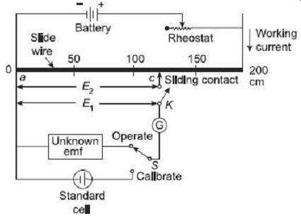
FIG. 1 A basic potentiometer circuit
3. CROMPTON'S dc POTENTIOMETER
The general arrangement of a laboratory-type Crompton's dc potentiometer is shown in FIG. 2. It consists of a dial switch which has fifteen (or more) steps. Each steep has 10 O resistance. So the dial switch has total 150 O resistance. The working current of this potentiometer is 10 mA and therefore each step of dial switch corresponds to 0.1 volt. So the range of the dial switch is 1.5 volt.
The dial switch is connected in series with a circular slide wire. The circular slide wire has 10 O resistance. So the range of that slide wire is 0.1 volt. The slide wire calibrated with 200 scale divisions and since the total resistance of slide wire corresponds to a voltage drop of 0.1 volt, each division of the slide wire corresponds to volt. It is quite comfortable to interpolate readings up to of a scale division and therefore with this Crompton's potentiometer it is possible to estimate the reading up to 0.0001 volt.
Procedure for Measurement of Unknown emf
• At first, the combination of the dial switch and the slide wire is set to the standard cell voltage. Let the standard sell voltage be 1.0175 volts, then the dial resistor is put in 1.0 volt and the slide wire at 0.0175 volts setting.
• The switch 'S' is thrown to the calibrate position and the galvanometer switch 'K' is pressed until the rheostat is adjusted for zero deflection on the galvanometer.
The 10 kW protective resistance is kept in the circuit in the initial stages so as to protect the galvanometer from overload.
• After the null deflection on the galvanometer is approached the protective resistance is shorted so as to increase the sensitivity of the galvanometer. Final adjustment is made for the zero deflection with the help of the rheostat. This completes the standardization process of the potentiometer.
• After completion of the standardization, the switch 'S' is thrown to the operate position thereby connecting the unknown emf into the potentiometer circuit. With the protective resistance in the circuit, the potentiometer is balanced by means of the main dial and the slide wire adjustment.
• As soon as the balanced is approached, the protective resistance is shorted and final adjustments are made to obtain true balance.
• After the final true balance is obtained, the value of the unknown emf is read off directly from the setting of the dial switch and the slide wire.
• The standardization of the potentiometer is checked again by returning the switch 'S' to the calibrate position. The dial setting is kept exactly the same as in the original standardization process. If the new reading does not agree with the old one, a second measurement of unknown emf must be made. The standardization again should be made after the measurement.
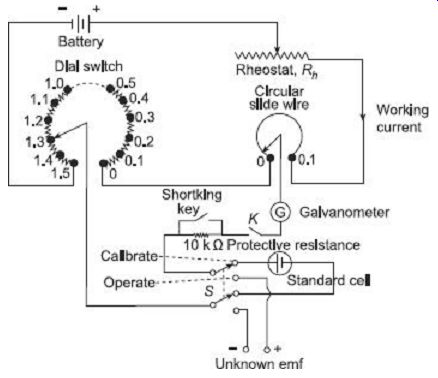
FIG. 2 General arrangement of Crompton' s dc potentiometer. A basic slide-wire
potentiometer has a working battery
4. APPLICATIONS of DC POTENTIOMETERS
Practical uses of dc potentiometers are
• Measurement of current
• Measurement of high voltage
• Measurement of resistance
• Measurement of power
• Calibration of voltmeter
• Calibration of ammeter
• Calibration of wattmeter
4.1 Measurement of Current by Potentiometer
The circuit arrangement for measurement of current by a potentiometer is shown in FIG. 3. The unknown current I, whose value is to be measured, is passed through a standard resistor R as shown. The standard resistor should be of such a value that voltage drop across it caused by flow of current to be measured, may not exceed the range of the potentiometer. Voltage drop across the standard resistor in volts divided by the value of R in ohms gives the value of unknown current in amperes.
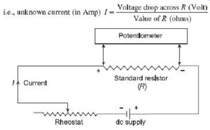
FIG. 3 Measurement of current with potentiometer
4.2 Measurement of High Voltage by Potentiometer
Special arrangements must be made to measure very high voltage by the potentiometer (say a hundreds of volts) as this high voltage is beyond the range of normal potentiometer.
The voltage above the direct range of potentiometer (generally 1.8 volt) can be measured by using a volt-ratio box in conjunction with the potentiometer. The volt-ratio box consists of a simple resistance potential divider with various tapping on the input side. The arrangement is shown in FIG. 4. Each input terminal is marked with the maximum voltage which can be applied and with the corresponding multiplying factor for the potential scale.
High emf to be measured is applied the suitable input terminal of volt-ratio box and leads to the potentiometer are taken from two tapping points intended for this purpose.
The potential difference across these two points is measured by the potentiometer. If the voltage measured by the potentiometer is v and k be the multiplying factor of the volt- ratio box, then the high voltage to be measured is V = kv volt.
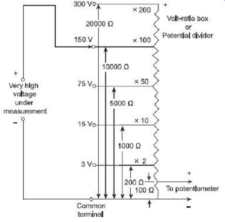
FIG. 4 Measurement of high voltage by potentiometer in conjunction with
volt-ratio box
4.3 Measurement of Resistance by Potentiometer
The connection diagram for measuring unknown resistance with the help of potentiometer is shown in FIG. 5. The unknown resistance R, is connected in series with the known standard resistor S. The rheostat connected in the circuit controls the current flowing through the circuit. An ammeter is also connected in the circuit to indicate whether the value of the working current is within the limit of the potentiometer or not. Otherwise, the exact value of the working current need not be known.
When the two-pole double throw switch is put in position 1, the unknown resistance is connected to the potentiometer. Let the reading of the potentiometer in that position is VR.
Then...
Now the switch is thrown to position 2, this connects the standard resistor S to the potentiometer. If the reading of the potentiometer is that position is VS then,...
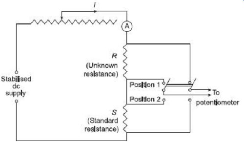
FIG. 5 Measurement of resistance by potentiometer
The value of R can be calculated accurately since the value of the standard resistor S is known. This method of measurement of resistance is used for low value of the resistor.
4.4 Measurement of Power by Potentiometer
In measurement of power by potentiometer the measurements are made one across the standard resistor S connected in series with the load and another across the volt-ratio box output terminals. The arrangement is shown in FIG. 6.
The load current which is exactly equal to the current through the standard resistor S, as it is connected in series with the load, is calculated from the voltage drop across the standard resistor divided by the value of the standard resistor S.
Load current where VS = voltage drop across standard resistor S as measured by the potentiometer.
Voltage drop across the load is found by the output terminal of the volt-ratio box. If VR is the voltage drop across the output terminal of the volt-ratio box and VL is the voltage drop across load then, VL = k × VR where k is the multiplying factor of the volt-ratio box.
Then the power consumed,
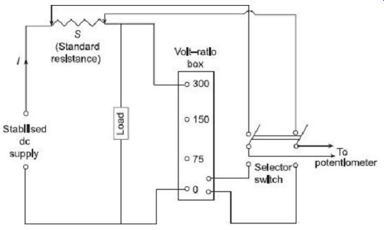
FIG. 6 Measurement of power by potentiometer
4.5 Calibration of Voltmeter by Potentiometer
In case of calibration of voltmeter, the main requirement is that a suitable stable dc voltage supply is available, otherwise any change in the supply voltage will cause a change in the calibration process of the voltmeter.
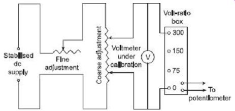
FIG. 7 Calibration of voltmeter by potentiometer The arrangement for
calibrating a voltmeter by potentiometer is shown in FIG. 7.
The potential divider network consists of two rheostats. One for coarse and the other for fine control of calibrating voltage. With the help of these controls, it is possible to adjust the supply voltage so that the pointer coincides exactly with a major division of the voltmeter.
The voltage across the voltmeter is steeped down to a value suitable for the potentiometer with the help of the volt-ratio box. In order to get accurate measurements, it is necessary to measure voltages near the maximum range of the potentiometer, as far as possible.
The potentiometer measures the true value of the voltage. If the reading of the potentiometer does not match with the voltmeter reading, a positive or negative error is indicated. A calibration curve may be drawn with the help of the potentiometer and the voltmeter reading.
4.6 Calibration of Ammeter by Potentiometer
FIG. 8 shows the circuit arrangement for calibration of an ammeter using potentiometer.
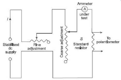
FIG. 8s Calibration of ammeter by potentiometer A standard resistor
S of high current carrying capacity is placed in series with the ammeter
under test. The voltage drop across S measured with the help of the potentiometer
and then the current through S and hence the ammeter can be computed by dividing
the voltage drop by the value of the standard resistor.
Current, is the voltage drop across the standard resistor S.
Now, compare the reading of the ammeter with the current found by calculation. If they do not match, a positive or negative error will be induced. A calibration curve may be drawn between the ammeter reading and the true value of the current as indicated by the potentiometer reading.
As the resistance of the standard resistor S is exactly known, the current through S is exactly calculated. This method of calibration of ammeter is very accurate.
4.7 Calibration of Wattmeter by Potentiometer
In this calibration process, the current coil of the wattmeter is supplied from low voltage supply and potential coil from the normal supply through potential divider. The voltage V across the potential coil of the wattmeter under calibration is measured directly by the potentiometer. The current through the current coil is measured by measuring the voltage drop across a standard resistor connected in series with the current coil divided by the value of the standard resistor.
The true power is then VI, where V is the voltage across the potential coil and I is the current through the current coil of the wattmeter. The wattmeter reading may be compared with this value, and a calibration curve may be drawn.
The arrangement for calibrating a wattmeter is shown in FIG. 9.
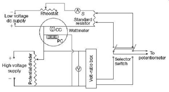
FIG. 9 Calibration of wattmeter by dc potentiometer
5. POTENTIOMETERS
An ac potentiometer is same as dc potentiometer by principle. Only the main difference between the ac and dc potentiometer is that, in case of dc potentiometer, only the magnitude of the unknown emf is compared with the standard cell emf, but in ac potentiometer, the magnitude as well as phase angle of the unknown voltage is compared to achieve balance.
This condition of ac potentiometer needs modification of the potentiometer as constructed for dc operation.
The following points need to be considered for the satisfactory operation of the ac potentiometer:
1. To avoid error in reading, the slide wire and the resistance coil of an ac potentiometer should be non-inductive.
2. The reading is affected by stray or external magnetic field, so in the time of measurement they must be eliminated or measured and corresponding correction factor should be introduced.
3. The sources of ac supply should be free from harmonics, because in presence of harmonics the balance may not be achieved.
4. The ac source should be as sinusoidal as possible.
5. The potentiometer circuit should be supplied from the same source as the voltage or current being measured.
6. CLASSIFICATION OF AC POTENTIOMETERS
There are two general types of ac potentiometers:
1. Polar Potentiometer
As the name indicates, in these potentiometers, the unknown emf is measured in polar form, i.e., in terms of its magnitude and relative phase. The magnitude is indicated by one scale and the phase with respect to some reference axis is indicated by another scale.
There is provision for reading phase angles up to 360°.
The voltage is read in the form V - ?.
Example: Drysdale polar potentiometer 2. Coordinate Potentiometer
Here, the unknown emf is measured in Cartesian form. Two components along and perpendicular to some standard axis are measured and indicated directly by two different scales known as in phase (V1) and quadrature (V2) scales (FIG. 10). Provision is made in this instrument to read both positive and negative values of voltages so that all angles up to 360° are covered.
Example: Gall-Tinsley and Campbell-Larsen type potentiometer
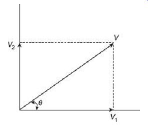
FIG. 10
Polar and coordinate representation of unknown emf
6.1 Drysdale Polar Potentiometer
The different components of a Drysdale polar potentiometer is shown in FIG. 11.
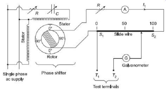
FIG. 11 Drysdale polar potentiometer
The slide wire S1-S2 is supplied from a phase shifting circuit for ac measurement. The phase shifting circuit is so arranged that the magnitude of the voltage supplied by it remains constant while its phase can be varied through 360°. Consequently, slide wire current can be maintained constant in magnitude but varied in phase.
The phase shifting circuit consists of two stator coils connected in parallel supplied from the same source; their currents are made to differ by 90° by using very accurate phase shifting technique. The two windings produce rotating flux which induces a secondary emf in the rotor winding which is of constant magnitude but the phase of which can be varied by rotating the rotor in any position. The phase of the rotor emf is read from the circular dial attached in the potentiometer.
Before the ac measurement, the potentiometer is first calibrated by using dc supply for slide wire and standard cell for test terminals T1 and T2. The unknown alternating voltage to be measured is applied across test terminals and the balance is achieved by varying the slide wire contact and the position of the rotor. The ammeter connected in the slide wire circuit gives the magnitude of the unknown emf and the circular dial in the rotor circuit gives the phase angle of it.
6.2 Gall Coordinate Potentiometer
The Gall coordinate potentiometer consists of two separate potentiometer circuit in a single case. One of them is called the 'in-phase' potentiometer and the other one is called the quadrature potentiometer. The slide-wire circuits of these two potentiometers are supplied with two currents having a phase difference of 90°. The value of the unknown voltage is obtained by balancing the voltages of in-phase and quadrature potentiometers slide wire simultaneously. If the measured values of in-phase and quadrature potentiometer slide-wires are V1 and V2 respectively then the magnitude of the unknown voltage is V = V1 2 +V2 2 and the phase angle of the unknown voltage is given by q = tan .
FIG. 12 shows the schematic diagram of a Gall coordinate-type potentiometer. W-X and Y-Z are the sliding contacts of the in-phase and quadrature potentiometer respectively. R and R' are two rheostats to control the two slide-wire currents. The in phase potentiometer slide-wire is supplied from a single-phase supply and the quadrature potentiometer slide-wire is supplied from a phase-splitting device to create a phase difference of 90° between the two slide-wire currents. T1 and T2 are two step-down transformers having an output voltage of 6 volts. These transformers also isolate the potentiometer from the high-voltage supply. R and C are the variable resistance and capacitance for phase-splitting purpose. VG is a vibration galvanometer which is tuned to the supply frequency and K is the galvanometer key. A is a dynamometer ammeter which is used to display the current in both the slide-wires so that they can be maintained at a standard value of 50 mA. SW1 and SW2 are two sign- changing switches which may be necessary to reverse the direction of unknown emf applied to the slide wires. SW3 is a selector switch and it is used to apply the unknown voltage to the potentiometer.
Operation Before using the potentiometer for ac measurements, the current in the in- phase potentiometer slide wire is first standardized using a standard dc cell of known value. The vibration galvanometer VG is replaced by a D'Arsonval galvanometer. Now the in-phase slide wire current is adjusted to the standard value of 50 mA by varying the rheostat R. This setting is left unchanged for ac calibration; the dc supply is replaced by ac and the D'Arsonval galvanometer by the vibration galvanometer.
The magnitude of the current in the quadrature potentiometer slide wire must be equal to the in- phase potentiometer slide wire current and the two currents should be exactly in quadrature. The switch SW3 is placed to test position (as shown in FIG. 12) so that the emf induced in the secondary winding of mutual inductance M is impressed across the in phase potentiometer wire through the vibration galvanometer. Since the induced emf in the secondary of mutual inductance M will be equal to 2pfMi volt in magnitude; where f is the supply frequency and will lag 90° behind the current in the quadrature slide-wire i, so the value of emf calculated from the relation e' =2pf Mi for a current i = 50 mA is set on in-phase potentiometer slide wire and R' are adjusted till exact balance point is obtained.
At balance position, the current in the potentiometer wires will be exactly equal to 50 mA in magnitude and exactly in quadrature with each other. The polarity difference between the two circuits is corrected by changing switches SW1 and SW2.
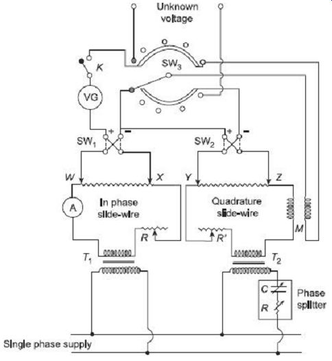
FIG. 12 Gall coordinate potentiometer
Lastly, the unknown voltage is applied to the potentiometer by means of the switch SW3 and balance is obtained on both the potentiometer slide-wire by adjusting the slide-wire setting. The reading of slide-wire WX gives the in-phase component (V1) and slide wire YZ gives quadrature component (V2) of the unknown voltage.
7. POTENTIOMETERS ADVANTAGES AND DISADVANTAGES OF AC
Advantages:
1. An ac potentiometer is a very versatile instrument. By using shunt and volt-ratio box, it can measure wide range of voltage, current and resistances.
2. As it is able to measure phase as well as magnitude of two signals, it is used to measure power, inductance and phase angle of a coil, etc.
3. The principle of ac potentiometer is also incorporated in certain special application like Arnold circuit for the measurement of CT (Current Transformer) errors.
Disadvantages
1. A small difference in reading of the dynamometer instrument either in dc or ac calibration brings on error in the alternating current to be set at standard value.
2. The normal value of the mutual inductance M is affected due to the introduction of mutual inductances of various potentiometer parts and so a slight difference is observed in the magnitude of the current of quadrature wire with compared to that in the in-phase potentiometer wire.
3. Inaccuracy in the measured value of frequency will also result in the quadrature potentiometer wire current to differ from that of in-phase potentiometer wire.
4. The presence of mutual inductances in the various parts of the potentiometer and the inter capacitance, the potential gradient of the wires is affected.
5. Since the standardization is done on the basis of rms value and balance is obtained dependent upon the fundamental frequency only, therefore, the presence of harmonics in the input signal introduces operating problem and the vibration galvanometer tuned to the fundamental frequency may not show full null position at all.
8. APPLICATIONS OF ac POTENTIOMETER
The major applications of the ac potentiometers are
1. Measurement of self-inductance
2. Calibration of voltmeter
3. Calibration of ammeter
4. Calibration of wattmeter
8.1 Measurement of Self-inductance
The circuit diagram for measurement of self inductance of a coil by ac potentiometer is shown in FIG. 13(a). A standard non-inductive resistor is connected in series with the coil under test and two potential differences V1 and V2 are measured in magnitude and phase by the potentiometer.
The vector diagram is shown in FIG. 13(b). Refer to this figure.
Voltage drop across standard resistor RS, V2 = IRS where, I= current flowing through the circuit, and
RS= resistance of the standard non-inductive resistor
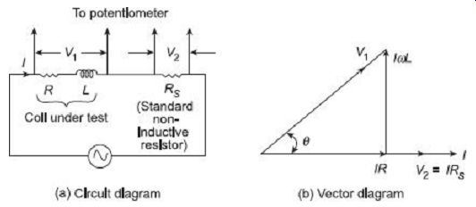
FIG. 13 Measurement of self-inductance by ac potentiometer Voltage drop
across inductive coil = V1 Phase angle between voltage across and current
through the coil = ? Voltage drop due to resistance of coil, IR= V1 cos ?
8.2 Calibration of Ammeter
The method of calibration of an ac ammeter is similar to dc potentiometer method for dc ammeter, i.e., ac ammeter under calibration is connected in series with a non inductive variable resistance for varying the current, and a non-inductive standard resistor and voltage drop across standard resistor is measured on ac potentiometer. However, the standardizing of the ac potentiometer involves the use of a suitable transfer instrument.
8.3 Calibration of Voltmeter
The method of calibration of an ac voltmeter by using ac potentiometer is similar to that adopted for calibration of dc voltmeter by using dc potentiometer.
8.4 Calibration of Wattmeter
The circuit diagram for calibration of wattmeter by ac potentiometer is shown in FIG. 14. The calibration process is same that adopted in case of calibration of wattmeter by dc potentiometer.
The current coil of the wattmeter is supplied through a stepdown transformer and the potential coil from the secondary of a variable transformer whose primary is supplied from the rotor of a phase shifting transformer. The voltage V across the potential coil of the wattmeter and the current I through the current coil of wattmeter are measured by the potentiometer, introducing a volt-ratio box and a standard resistor as shown in FIG. 14.
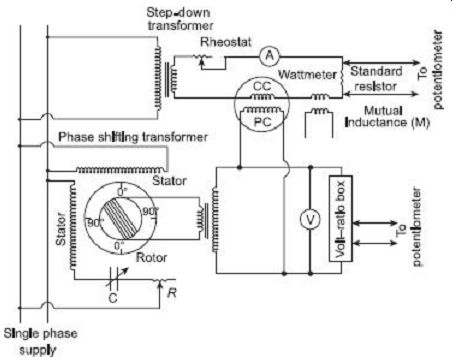
FIG. 14 Calibration of wattmeter by ac potentiometer
The power factor cos q is varied by rotating the phase shift rotor, the phase angle between voltage and current, F being given by the reading on the dial of the phase shifter.
The power is then VI cos F and the wattmeter reading may be compared with this reading.
A calibration curve may be drawn if necessary. A small mutual inductance M is included to ensure accuracy of measurement of zero power factor.
QUIZ
Objective Questions
1. The transfer instrument which is used for standardization of a polar-type ac potentiometer is (a) an electrostatic instrument (b) a dynamometer instrument (c) a moving coil instrument (d) a thermal instrument
2. A dc potentiometer is designed to measure up to about 2 volts with a slide wire of 800 mm. A standard cell of emf 1.18 volt obtains balance at 600 mm. a test cell is seen to obtained balance at 680 mm. The emf of the test cell is (a) 1.50 volts (b) 1.00 volts (c) 1.34 volts (d) 1.70 volts
3. For measuring an ac voltage by an ac potentiometer, it is desirable that the supply for the potentiometer is taken from (a) a battery (b) the same source as the unknown voltage (c) a source other than the source of unknown voltage (d) any of the above
4. The calibration of a voltmeter can be carried out by using (a) an ammeter (b) a function generator (c) a frequency meter (d) a potentiometer
5. A slide wire potentiometer has 10 wires of 1 m each. With the help of a standard voltage source of 1.018 volt it is standardize by keeping the jockey at 101.8 cm. If the resistance of the potentiometer wire is 1000 O then the value of the working current is (a) 1 mA (b) 0.5 mA (c) 0.1 A (d) 10 mA
6. In the potentiometer circuit, the value of the unknown voltage E under balance condition will be (a) 3 V (b) 200 mV (c) 2.8 V (d) 3.2 V
7. The potentiometer is standardized for making it (a) precise (b) accurate (c) accurate and precise (d) accurate and direct reading
8. Consider the following statements. A dc potentiometer is the best means available for the measurement of dc voltage because:
1. The precision in measurement is independent of the type of detector used
2. It is based on null balance technique
3. It is possible to standardize before a measurement is undertaken
4. It is possible to measure dc voltages ranging in value from mV to hundreds of volts
Of these statements, (a) 2 and 3 are correct (b) 1 and 4 are correct (c) 2 and 4 are correct (d) 3 and 4 are correct 9. In a dc potentiometer measurements, a second reading is often taken after reversing the polarities of dc supply and the unknown voltage, and the average of the two readings is taken. This is with a view to eliminate the effects of (a) ripples in the dc supply (b) stray magnetic field (c) stray thermal emfs (d) erroneous standardization
Questions
1. Explain why a potentiometer does not load the voltage source whose voltage is being measured.
2. Describe the procedure of standardization of a dc potentiometer.
3. What is a volt ratio box? Explain its principle with a suitable block diagram.
4. Explain the reasons why dc potentiometers cannot be used for ac measurement directly.
5. Explain the procedure for measurement of self-reactance of a coil with the help of ac potentiometer.
6. What is the difference between a slide-wire potentiometer and direct reading potentiometer?
7. How can a dc potentiometer be used for calibration of voltmeter?
8. Explain with suitable diagram how a dc potentiometer can be used for calibration of an ammeter.
9. Explain with a suitable diagram how a dc potentiometer can be used for calibration of wattmeter.
10. What are the different forms of ac potentiometers and bring out the differences between them.
More Questions
1. (a) Explain the working principle of a Crompton dc potentiometer with a suitable diagram.
(b) The emf of a standard cell is measured with a potentiometer which gives a reading of 1.01892 volts. When a 1 MO resistor is connected across the standard cell terminals, the potentiometer reading drops to 1.01874 volts.
Calculate the internal resistance of the cell.
[Ans: 176.6 O]
2. (a) Name the different types of dc potentiometers and explain one of them.
(b) A slidewire potentiometer is used to measure the voltage between the two points of a certain dc circuit. The potentiometer reading is 1.0 volt. Across the same two points when a 10000 O/V voltmeter is connected, the reading on the voltmeter is 0.5 volt of its 5-volt range. Calculate the input resistance between two points.
[Ans: 50000 O]
3. (a) Write down the procedure of standardization of a dc potentiometer. How can it be used for calibration of ammeters and voltmeters?
(b) A slidewire potentiometer has a battery of 4 volts and negligible internal resistance. The resistance of slide wire is 100 O and its length is 200 cm. A standard cell of 1.018 volts is used for standardizing the potentiometer and the rheostat is adjusted so that balance is obtained when the sliding contact is at 101.8 cm.
(i) Find the working current of the slidewire and the rheostat setting.
[Ans: 20 mA, 100 O]
(ii) If the slidewire has divisions marked in mm and each division can be interpolated to one fifth, calculate the resolution of the potentiometer.
[Ans: 0.2 mV]
4. (a) What are the problems associated with ac potentiometers? Describe the working of any one ac potentiometer.
(b) Power is being measured with an ac potentiometer. The voltage across a 0.1 O standard resistance connected in series with the load is (0.35 - j0.10) volt. The voltage across 300:1 potential divider connected to the supply is (0.8 + j0.15) volt. Determine the power consumed by the load and the power factor.
[Ans: 801 W, 0.8945]
5. (a) Describe the construction and working of an ac coordinate-type potentiometer.
(b) Measurements for the determination of the impedance of a coil are made on a coordinate type potentiometer.
The result are: Voltage across 1 O standard resistance in series with the coil = +0.952 V on in-phase dial and - 0.340 V on quadrature dial; voltage across 10:1 potential divider connected to the terminals of the coil = +1.35 V on in phase dial and +1.28 V on quadrature dial.
Calculate the resistance and reactance of the coil.
[Ans: R = 8.32 O, × = 16.41 O]
6. Describe briefly the applications of ac potentiometers.
7. Write short notes on the following (any three):
(a) Simple dc potentiometer and its uses (b) Calibration of low range ammeter (c) Measurement of high voltage by dc potentiometer (d) Polar potentiometer (e) Coordinate-type potentiometer (f) Comparison between ac and dc potentiometer