AMAZON multi-meters discounts AMAZON oscilloscope discounts
1. INTRODUCTION
Alternating current bridges are most popular, convenient and accurate instruments for measurement of unknown inductance, capacitance and some other related quantities. In its simplest form, ac bridges can be thought of to be derived from the conventional dc Wheatstone bridge. An ac bridge, in its basic form, consists of four arms, an alternating power supply, and a balance detector.
2. SOURCES AND DETECTORS IN AC BRIDGES
For measurements at low frequencies, bridge power supply can be obtained from the power line itself. Higher frequency requirements for power supplies are normally met by electronic oscillators. Electronic oscillators have highly stable, accurate yet adjustable frequencies. Their output waveforms are very close to sinusoidal and output power level sufficient for most bridge measurements.
When working at a single frequency, a tuned detector is preferred, since it gives maximum sensitivity at the selected frequency and discrimination against harmonic frequencies. Vibration galvanometers are most commonly used as tuned detectors in the power frequency and low audio-frequency ranges. Though vibration galvanometers can be designed to work as detectors over the frequency range of 5 Hz to 1000 Hz, they have highest sensitivity when operated for frequencies below 200 Hz.
Head phones or audio amplifiers are popularly used as balance detectors in ac bridges at frequencies of 250 Hz and above, up to 3 to 4 kHz.
Transistor amplifier with frequency tuning facilities can be very effectively used as balance detectors with ac bridges. With proper tuning, these can be used to operate at a selective band of frequencies with high sensitivity. Such detectors can be designed to operate over a frequency range of 10 Hz to 100 kHz.
3. GENERAL BALANCE EQUATION FOR FOUR-ARM BRIDGE
An ac bridge in its general form is shown in FIG. 1, with the four arms being represented by four unspecified impedances Z1, Z2, Z3 and Z4.
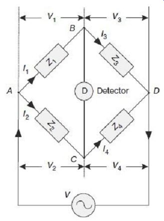
FIG. 1 General 4-arm bridge configuration Balance in the bridge is secured
by adjusting one or more of the bridge arms. Balance is indicated by zero
response of the detector. At balance, no current flows through the detector,
i.e., there is no potential difference across the detector, or in other words,
the potentials at points B and C are the same. This will be achieved if the
voltage drop from A to B equals the voltage drop from A to C, both in magnitude
and phase.
Thus, we can write in terms of complex quantities:
Also at balance, since no current flows through the detector, Combining Eqs (2) and (3) into Eq. (1), we have When using admittances in place of impedances, Eq. (4) can be re-oriented as Equations (4) and (6) represent the basic balance equations of an ac bridge. Whereas (4) is convenient for use in bridge configurations having series elements, (6) is more useful when bridge configurations have parallel elements.
Equation (4) indicates that under balanced condition, the product of impedances of one pair of opposite arms must be equal to the product of impedances of the other pair of opposite arms, with the impedances expressed as complex numbers. This will mean, both magnitude and phase angles of the complex numbers must be taken into account.
Re-writing the expressions in polar form, impedances can be expressed as where Z represents the magnitude and ? represents the phase angle of the complex impedance.
If similar forms are written for all impedances and substituted in (4), we obtain:
Thus, for balance we have, Equation (7) shows that two requirements must be met for satisfying balance condition in a bridge.
The first condition is that the magnitude of the impedances must meet the relationship; The second condition is that the phase angles of the impedances must meet the relationship;
4. MEASUREMENT OF SELF-INDUCTANCE
4.1 Maxwell's Inductance Bridge
This bridge is used to measure the value of an unknown inductance by comparing it with a variable standard self-inductance. The bridge configuration and phasor diagram under balanced condition are shown in FIG. 2.
The unknown inductor L1 of resistance R1 in the branch AB is compared with the standard known inductor L2 of resistance R2 on arm AC. The inductor L2 is of the same order as the unknown inductor L1. The resistances R1, R2, etc., include, of course the resistances of contacts and leads in various arms. Branch BD and CD contain known no inductive resistors R3 and R4 respectively.
The bridge is balanced by varying L2 and one of the resistors R3 or R4. Alternatively, R3 and R4 can be kept constant, and the resistance of one of the other two arms can be varied by connecting an additional resistor.
Under balanced condition, no current flows through the detector. Under such condition, currents in the arms AB and BD are equal (I1). Similarly, currents in the arms AC and CD are equal (I2). Under balanced condition, since nodes B and D are at the same potential, voltage drops across arm BD and CD are equal (V3 = V4); similarly, voltage drop across arms AB and AC are equal (V1 = V2).
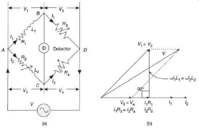
FIG. 2 Maxwell' s inductance bridge under balanced condition: (a) Configuration
(b) Phasor diagram As shown in the phasor diagram of FIG. 2 (b), V3 and
V4 being equal, they are overlapping. Arms BD and CD being purely resistive,
currents through these arms will be in the same phase with the voltage
drops across these two respective branches. Thus, currents I1 and I2 will
be collinear with the phasors V3 and V4. The same current I1 flows through
branch AB as well, thus the voltage drop I1R1 remains in the same phase as
I1.
Voltage drop wI1L1 in the inductor L1 will be 90° out of phase with I1R1 as shown in FIG. 2(b). Phasor summation of these two voltage drops I1R1 and wI1L1 will give the voltage drop V1 across the arm AB. At balance condition, since voltage across the two branches AB and AC are equal, thus the two voltage drops V1 and V2 are equal and are in the same phase. Finally, phasor summation of V1 and V3 (or V2 and V4) results in the supply voltage V.
Unknown quantities can hence be calculated as Care must be taken that the inductors L1 and L2 must be placed at a distance from each other to avoid effects of mutual inductance.
The final expression (10) shows that values of L1 and R1 do not depend on the supply frequency. Thus, this bridge configuration is immune to frequency variations and even harmonic distortions in the power supply.
4.2 Maxwell's Inductance-Capacitance Bridge
In this bridge, the unknown inductance is measured by comparison with a standard variable capacitance. It is much easier to obtain standard values of variable capacitors with acceptable degree of accuracy. This is however, not the case with finding accurate and stable standard value variable inductor as is required in the basic Maxwell's bridge described in Section 4.1.
Configuration of a Maxwell's inductance-capacitance bridge and the associated phasor diagram at balanced state are shown in FIG. 3.
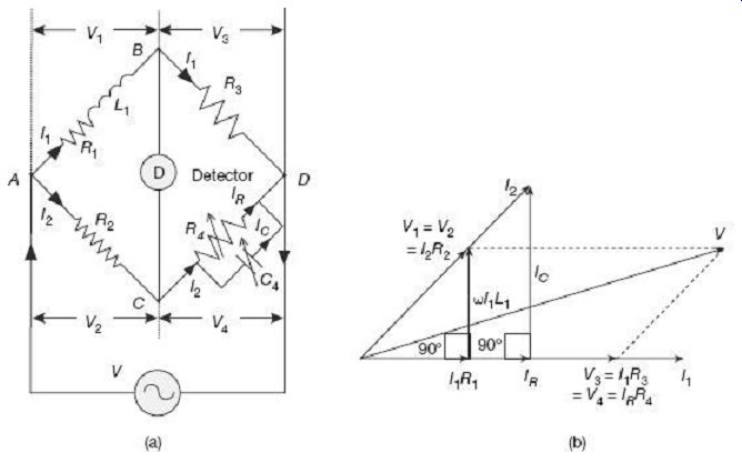
FIG. 3 Maxwell's inductance-capacitance bridge under balanced condition:
(a) Configuration (b) Phasor diagram The unknown inductor L1 of effective
resistance R1 in the branch AB is compared with the standard known variable
capacitor C4 on arm CD. The other resistances R2, R3, and R4 are known
as non-inductive resistors.
The bridge is preferably balanced by varying C4 and R4, giving independent adjustment settings.
Under balanced condition, no current flows through the detector. Under such condition, currents in the arms AB and BD are equal (I1). Similarly, currents in the arms AC and CD are equal (I2). Under balanced condition, since nodes B and D are at the same potential, voltage drops across arm BD and CD are equal (V3 = V4); similarly, voltage drops across arms AB and AC are equal (V1 = V2).
As shown in the phasor diagram of FIG. 3 (b), V3 and V4 being equal, they are overlapping both in magnitude and phase. The arm BD being purely resistive, current I1 through this arm will be in the same phase with the voltage drop V3 across it. Similarly, the voltage drop V4 across the arm CD, current IR through the resistance R4 in the same branch, and the resulting resistive voltage drop IRR4 are all in the same phase [horizontal line in FIG. 3(b)]. The resistive current IR when added with the quadrature capacitive current IC, results in the main current I2 flowing in the arm CD. This current I2 while flowing through the resistance R2 in the arm AC, produces a voltage drop V2 = I2R2, that is in same phase as I2. Under balanced condition, voltage drops across arms AB and AC are equal, i.e., V1 = V2. This voltage drop across the arm AB is actually the phasor summation of voltage drop I1R1 across the resistance R1 and the quadrature voltage drop wI1L1 across the unknown inductor L1. Finally, phasor summation of V1 and V3 (or V2 and V4) results in the supply voltage V.
Equating real and imaginary parts, we have...
Thus, the unknown quantities are Once again, the final expression (11) shows that values of L1 and R1 do not depend on the supply frequency. Thus, this bridge configuration is immune to frequency variations and even harmonic distortions in the power supply.
It is interesting to note that both in the Maxwell's Inductance Bridge and Inductance Capacitance Bridge, the unknown Inductor L1 was always associated with a resistance R1.
This series resistance has been included to represent losses that take place in an inductor coil. An ideal inductor will be lossless irrespective of the amount of current flowing through it. However, any real inductor will have some non-zero resistance associated with it due to resistance of the metal wire used to form the inductor winding. This series resistance causes heat generation due to power loss. In such cases, the Quality Factor or the Q-Factor of such a lossy inductor is used to indicate how closely the real inductor comes to behave as an ideal inductor. The Q-factor of an inductor is defined as the ratio of its inductive reactance to its resistance at a given frequency. Q-factor is a measure of the efficiency of the inductor. The higher the value of Q-factor, the closer it approaches the behavior of an ideal, loss less inductor. An ideal inductor would have an infinite Q at all frequencies.
The Q-factor of an inductor is given by the formula , where R is its internal resistance R (series resistance) and wL is its inductive reactance at the frequency _.
Q-factor of an inductor can be increased by either increasing its inductance value (by using a good ferromagnetic core) or by reducing its winding resistance (by using good quality conductor material, in special cases may be super conductors as well).
In the Maxwell's Inductance-Capacitance Bridge, Q-factor of the inductor under measurement can be found at balance condition to be or, The above relation (12) for the inductor Q factor indicate that this bridge is not suitable for measurement of inductor values with high Q factors, since in that case, the required value of R4 for achieving balance becomes impracticably high.
Advantages of Maxwell's Bridge
1. The balance equations (11) are independent of each other, thus the two variables C4 and R4 can be varied independently.
2. Final balance equations are independent of frequency.
3. The unknown quantities can be denoted by simple expressions involving known quantities.
4. Balance equation is independent of losses associated with the inductor.
5. A wide range of inductance at power and audio frequencies can be measured.
Disadvantages of Maxwell's Bridge
1. The bridge, for its operation, requires a standard variable capacitor, which can be very expensive if high accuracies are asked for. In such a case, fixed value capacitors are used and balance is achieved by varying R4 and R2.
2. This bridge is limited to measurement of low Q inductors (1< Q < 10).
3. Maxwell's bridge is also unsuited for coils with very low value of Q (e.g., Q < 1).
Such low Q inductors can be found in inductive resistors and RF coils. Maxwell's bridge finds difficult and laborious to obtain balance while measuring such low Q inductors.
4.3 Hay's Bridge
Hay's bridge is a modification of Maxwell's bridge. This method of measurement is particularly suited for high Q inductors.
Configuration of Hay's bridge and the associated phasor diagram under balanced state are shown in FIG. 4.
The unknown inductor L1 of effective resistance R1 in the branch AB is compared with the standard known variable capacitor C4 on arm CD. This bridge uses a resistance R4 in series with the standard capacitor C4 (unlike in Maxwell's bride where R4 was in parallel with C4). The other resistances R2 and R3 are known no-inductive resistors.
The bridge is balanced by varying C4 and R4.
Under balanced condition, since no current flows through the detector, nodes B and D are at the same potential, voltage drops across arm BD and CD are equal (V3 = V4);
similarly, voltage drops across arms AB and AC are equal (V1 = V2).
FIG. 4 Hay' s bridge under balanced condition: (a) Configuration, (b) Phasor diagram As shown in the phasor diagram of FIG. 4 (b), V3 and V4 being equal, they are overlapping both in magnitude and phase and are draw on along the horizontal axis. The arm BD being purely resistive, current I1 through this arm will be in the same phase with the voltage drop V3 = I1R3 across it. The same current I1, while passing through the resistance R1 in the arm AB, produces a voltage drop I1R1 that is once again, in the same phase as I 1. Total voltage drop V 1 across the arm AB is obtained by adding the two quadrature phasors I 1R 1 and wI 1L 1 representing resistive and inductive voltage drops in the same branch AB. Since under balance condition, voltage drops across arms AB and AC are equal, i.e., (V 1 = V 2), the two voltages V 1 and V 2 are overlapping both in magnitude and phase. The branch AC being purely resistive, the branch current I 2 and branch voltage V 2 will be in the same phase as shown in the phasor diagram of FIG. 4 (b). The same current I 2 flows through the arm CD and produces a voltage drop I 2R 4 across the resistance R 4. This resistive voltage drop I 2R 4, obviously is in the same phase as I 2. The capacitive voltage drop I 2/wC 4 in the capacitance C 4 present in the same arm AC will however, lag the current I 2 by 90°. Phasor summation of these two series voltage drops across R 4 and C 4 will give the total voltage drop V 4 across the arm CD. Finally, phasor summation of V 1 and V 3 (or V 2 and V 4) results in the supply voltage V.
Equating real and imaginary parts, we have Solving Eqs (13) and (14) we have the unknown quantities as and Q factor of the inductor in this case can be calculated at balance condition as Hay's bridge is more suitable for measurement of unknown inductors having Q factor more than 10. In those cases, bridge balance can be attained by varying R2 only, without losing much accuracy.
From (15) and (17), the unknown inductance value can be written as ...
For inductors with Q > 10, the quantity (1/Q) 2 will be less than 1/100, and thus can be neglected from the denominator of (18). In such a case, the inductor value can be simplified to L1 = R2R3C4, which essentially is the same as obtained in Maxwell's bridge.
4.4 Anderson's Bridge
This method is a modification of Maxwell's inductance-capacitance bridge, in which value of the unknown inductor is expressed in terms of a standard known capacitor. This method is applicable for precise measurement of inductances over a wide range of values.
FIG. 5 shows Anderson's bridge configuration and corresponding phasor diagram under balanced condition.
The unknown inductor L1 of effective resistance R1 in the branch AB is compared with the standard known capacitor C on arm ED. The bridge is balanced by varying r.
Under balanced condition, since no current flows through the detector, nodes B and E are at the same potential.
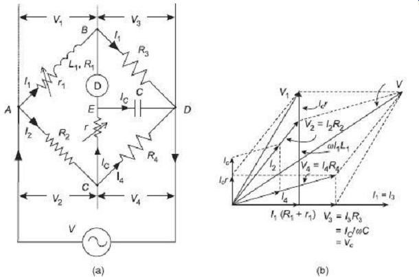
FIG. 5 Anderson' s bridge under balanced condition: (a) Configuration
(b) Phasor diagram As shown in the phasor diagram of FIG. 5 (b), I1 and
V3 = I1R3 are in the same phase along the horizontal axis. Since under balance
condition, voltage drops across arms BD and ED are equal, V3 = I1R3 = IC/wC
and all the three phasors are in the same phase.
The same current I1, when flowing through the arm AB produces a voltage drop I1(R1 + r1) which is once again, in phase with I1. Since under balanced condition, no current flows through the detector, the same current IC flows through the resistance r in arm CE and then through the capacitor C in the arm ED. Phasor summation of the voltage drops ICr in arm the CE and IC /wC in the arm ED will be equal to the voltage drop V4 across the arm CD. V4 being the voltage drop in the resistance R4 on the arm CD, the current I4 and V4 will be in the same phase. As can be seen from the Anderson's bridge circuit, and also plotted in the phasor diagram, phasor summation of the currents I4 in the arm CD and the current IC in the arm CE will give rise to the current I2 in the arm AC. This current I2, while passing through the resistance R2 will give rise to a voltage drop V2 = I2R2 across the arm AC that is in phase with the current I2. Since, under balance, potentials at nodes B and E are the same, voltage drops between nodes A -B and between A -C -E will be equal.
Thus, phasor summation of the voltage drop V2 = I2R2 in the arm AC IC r in arm the CE will build up to the voltage V1 across the arm AB. The voltage V1 can also be obtained by adding the resistive voltage drop I1(R1 + r1) with the quadrature inductive voltage drop wI1L1 in the arm AB. Finally, phasor summation of V1 and V3 (or V2 and V4) results in the supply voltage V.
At balance, I2 = IC + I4
Putting the value of IC from Eq. (19) in Eq. (20), we have: Ir ( +R +jwL ) =IR +jwI RCr
Then, putting the value of IC from Eq. (19) in Eq. (21), we have:Ê1 ˆ From Eqs (22) and (23), we obtain:
Equating real and imaginary parts, we get The advantage of Anderson's bridge over Maxwell's bride is that in this case a fixed value capacitor is used thereby greatly reducing the cost. This however, is at the expense of connection complexities and balance equations becoming tedious.
4.5 Owen's Bridge
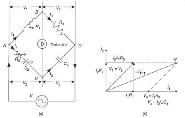
FIG. 6 Owen' s bridge under balanced condition: (a) Configuration (b)
Phasor diagram
This bridge is used for measurement of unknown inductance in terms of known value capacitance.
FIG. 6 shows the Owen's bridge configuration and corresponding phasor diagram under balanced condition.
The unknown inductor L1 of effective resistance R1 in the branch AB is compared with the standard known capacitor C2 on arm AC. The bridge is balanced by varying R2 and C2 independently.
Under balanced condition, since no current flows through the detector, nodes B and C are at the same potential, i.e., V1 = V2 and V3 = V4.
As shown in the phasor diagram of FIG. 5 (b), I1, V3 = I1R3 and V4 = I2/wC4 are all in the same phase along the horizontal axis. The resistive voltage drop I1R1 in the arm AB is also in the same phase with I1. The inductive voltage drop wI1L1 when added in quadrature with the resistive voltage drop I1R1 gives the total voltage drop V1 across the arm AB. Under balance condition, voltage drops across arms AB and AC being equal, the voltages V1 and V2 coincide with each other as shown in the phasor diagram of FIG. 6 (b). The voltage V2 is once again summation of two mutually quadrature voltage drops I2R2 (resistive) and I2/wC2 (capacitive) in the arm AC. It is to be noted here that the current I2 leads the voltage V4 by 90° due to presence of the capacitor C4. This makes I2 and hence I2R2 to be vertical, as shown in the phasor diagram. Finally, phasor summation of V1 and V3 (or V2 and V4) results in the supply voltage V.
Simplifying and separating real and imaginary parts, the unknown quantities can be found out as and It is thus possible to have two independent variables C2 and R2 for obtaining balance in Owen's bridge. The balance equations are also quite simple. This however, does come with additional cost for the variable capacitor
5 MEASUREMENT OF CAPACITANCE
Bridges are used to make precise measurements of unknown capacitances and associated losses in terms of some known external capacitances and resistances. An ideal capacitor is formed by placing a piece of dielectric material between two conducting plates or electrodes. In practical cases, this dielectric material will have some power losses in it due to dielectric's conduction electrons and also due to dipole relaxation phenomena. Thus, whereas an ideal capacitor will not have any losses, a real capacitor will have some losses associated with its operation. The potential energy across a capacitor is thus dissipated in all real capacitors as heat loss inside its dielectric material. This loss is equivalently represented by a series resistance, called the equivalent series resistance (ESR). In a good capacitor, the ESR is very small, whereas in a poor capacitor the ESR is large. C real C ideal ESR A real, lossy capacitor can thus be equivalently represented by an ideal loss less capacitor in series CR with its equivalent series resistance (ESR) shown FIG. 7 Equivalent series resistance (ESR) in FIG. 7.
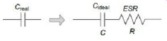
FIG. 7 Equivalent series resistance (ESR)
The quantifying parameters often used to describe performance of a capacitor are ESR, its dissipation factor (DF), Quality Factor (Q-factor) and Loss Tangent (tan d). Not only that these parameters describe operation of the capacitor in radio frequency (RF) applications, but ESR and DF are also particularly important for capacitors operating in power supplies where a large dissipation factor will result in large amount of power being wasted in the capacitor. Capacitors with high values of ESR will need to dissipate large amount of heat. Proper circuit design needs to be practiced so as to take care of such possibilities of heat generation.
Dissipation factor due to the non-ideal capacitor is defined as the ratio of the resistive power loss in the ESR to the reactive power oscillating in the capacitor, or When representing the electrical circuit parameters as phasors, a capacitor's dissipation factor is equal to the tangent of the angle between the capacitor's impedance phasor and the negative reactive axis, as shown in the impedance triangle diagram of FIG. 8 This gives rise to the parameter known as the loss tangent d where Figure. 6.8 Impedance Figure. 6.8 Impedance triangle diagram Loss tangent of a real capacitor can also be defined in the voltage triangle diagram of FIG. 9 as the ratio of voltage drop across the ESR to the voltage drop across the capacitor only, i.e. tangent of the angle between the capacitor voltage only and the total voltage drop across the combination of capacitor and ESR.
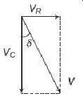
Fig. 9 Voltage triangle diagram
Though the expressions for dissipation factor (DF) and loss tangent (tan d) are the same, normally the dissipation factor is used at lower frequencies, whereas the loss tangent is more applicable for high frequency applications. A good capacitor will normally have low values of dissipation factor (DF) and loss tangent (tan d).
In addition to ESR, DF and loss tangent, the other parameter used to quantify performance of a real capacitor is its Quality Factor or Q-Factor. Essentially for a capacitor it is the ratio of the energy stored to that dissipated per cycle.
It can thus be deduced that the Q can be expressed as the ratio of the capacitive reactance to the ESR at the frequency of interest.
A high quality capacitor (high Q-factor) will thus have low values of dissipation factor (DF) and loss tangent (tan d), i.e. less losses.
The most commonly used bridges for capacitance measurement are De Sauty's bridge and Schering Bridge.
5.1 De Sauty's Bridge
This is the simplest method of finding out the value of a unknown capacitor in terms of a known standard capacitor. Configuration and phasor diagram of a De Sauty's bridge under balanced condition is shown in FIG. 10.
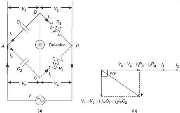
FIG. 10 De Sauty' s bridge under balanced condition: (a) Configuration
(b) Phasor diagram
The unknown capacitor C1 in the branch AB is compared with the standard known standard capacitor C2 on arm AC. The bridge can be balanced by varying either of the non-inductive resistors R3 or R4.
Under balanced condition, since no current flows through the detector, nodes B and C are at the same potential, i.e., V1 = V2 and V3 = V4.
As shown in the phasor diagram of FIG. 7 (b), V3 = I1R3 and V4 = I2R4 being equal both in magnitude and phase, they overlap. Current I1 in the arm BD and I2 in the arm CD are also in the same phase with I1R3 and I2R4 along the horizontal line. Capacitive voltage drop V1 = I1/wC1 in the arm AB lags behind I1 by 90°. Similarly, the other capacitive voltage drop V2 = I2/wC2 in the arm AC lags behind I2 by 90°. Under balanced condition, these two voltage drops V1 and V2 being equal in magnitude and phase, they overlap each other along the vertical axis as shown in FIG. 7 (b). Finally, phasor summation of V1 and V3 (or V2 and V4) results in the supply voltage V.
The advantage of De Sauty's bridge is its simplicity. However, this advantage may be nullified by impurities creeping in the measurement if the capacitors are not free from dielectric losses. This method is thus best suited for loss-less air capacitors.
In order to make measurement in capacitors having inherent dielectric losses, the modified De Sauty' s bridge as suggested by Grover, can be used. This bridge is also called the series resistance-capacitance bridge. Configuration of such a bridge and its corresponding phasor diagram under balanced condition is shown in FIG. 11.
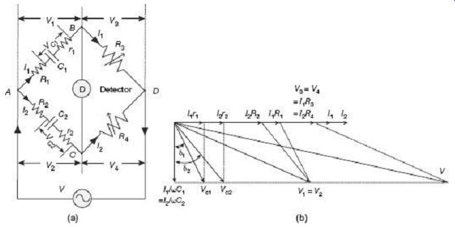
FIG. 11 Modified De Sauty' s bridge under balanced condition: (a) Configuration,
and (b) Phasor diagram
The unknown capacitor C1 with internal resistance r1 representing losses in the branch AB is compared with the standard known standard capacitor C2 along with its internal resistance r2 on arm AC. Resistors R1 and R2 are connected externally in series with C1 and C2 respectively. The bridge can be balanced by varying either of the non-inductive resistors R3 or R4.
Under balanced condition, since no current flows through the detector, nodes B and C are at the same potential, i.e., V1 = V2 and V3 = V4.
As shown in the phasor diagram of FIG. 11 (b), V3 = I1R3 and V4 = I2R4 being equal both in magnitude and phase, they overlap. Current I1 in the arm BD and I2 in the arm CD are also in the same phase with I1R3 and I2R4 along the horizontal line. The other resistive drops, namely, I1R1 in the arm AB and I2R2 in the arm AC are also along the same horizontal line. Finally, resistive drops inside the capacitors, namely, I1r1 and I2r2 are once again, in the same phase, along the horizontal line. Capacitive voltage drops I1/wC1 lags behind I1r1 by 90°. Similarly, the other capacitive voltage drop I2/wC2 lags behind I2r2 by 90°. Phasor summation of the resistive drop I1r1 and the quadrature capacitive drop I1/ wC1 produces the total voltage drop VC1 across the series combination of capacitor C1 and its internal resistance r1. Similarly, phasor summation of the resistive drop I2r2 and the quadrature capacitive drop I2/wC2 produces the total voltage drop VC2 across the series combination of capacitor C2 and its internal resistance r2. d1 and d2 represent loss angles for capacitors C1 and C2 respectively. Phasor summation of I1R1 and VC1 gives the total voltage drop V1 across the branch AB. Similarly, phasor summation of I2R2 and VC2 gives the total voltage drop V2 across the branch AC. Finally, phasor summation of V1 and V3 (or V2 and V4) results in the supply voltage V.
Equating real and imaginary parts, we have The modified De Sauty's bridge can also be used to estimate dissipation factor for the unknown capacitor as described below:
Dissipation factor for the capacitors are defined as From Eq. (29), we have:
Using Eq. (31), we get or, D -D =w (CR -CR ) Substituting the value of C1 from Eq. (30), we have Thus, dissipation factor for one capacitor can be estimated if dissipation factor of the other capacitor is known.
5.2 Schering Bridge
Schering bridges are most popularly used these days in industries for measurement of capacitance, dissipation factor, and loss angles. FIG. 12 illustrates the configuration of a Schering bridge and corresponding phasor diagram under balanced condition.
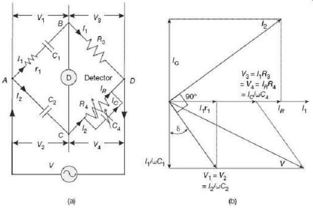
FIG. 12 Schering bridge under balanced condition: (a) Configuration
(b) Phasor diagram The unknown capacitor C1 along with its internal resistance
r1 (representing loss) placed on the arm AB is compared with the standard
loss-less capacitor C2 placed on the arm AC. This capacitor C2 is either
an air or a gas capacitor to make it loss free. R3 is a non-inductive resistance
placed on arm BD. The bridge is balanced by varying the capacitor C4 and
the non-inductive resistor R4 parallel with C4, placed on arm CD.
Under balanced condition, since no current flows through the detector, nodes B and C are at the same potential, i.e., V1 = V2 and V3 = V4.
As shown in the phasor diagram of FIG. 12 (b), V3 = I1R3 and V4 = IRR4 being equal both in magnitude and phase, they overlap. Current I1 in the arm BD and IR flowing through R4 are also in the same phase with I1R3 and IRR4 along the horizontal line. The other resistive drop namely, I1R1 in the arm AB is also along the same horizontal line. The resistive current IR through R4 and the quadrature capacitive current IC through C4 will add up to the total current I2 in the branch CD (and also in A C under balanced condition).
Across the arm AB, the resistive drop I1r1 and the quadrature capacitive drop I1/wC1 will add up to the total voltage drop V1 across the arm. At balance, voltage drop V1 across arm AB will be same as the voltage drop V2 = I2/wC2 across the arm AC. It can be confirmed from the phasor diagram in FIG. 12(b) that the current I2 has quadrature phase relationship with the capacitive voltage drop I2/wC2 in the arm AC. Finally, phasor summation of V1 and V3 (or V2 and V4) results in the supply voltage V.
Equating real and imaginary parts, we have the unknown quantities: and Dissipation Factor Thus, using Schering bridge, dissipation factor can be obtained in terms of the bridge parameters at balance condition.
6. MEASUREMENT OF FREQUENCY
6.1 Wien's Bridge
Wien's bridge is primarily used for determination of an unknown frequency. However, it can be used for various other applications including capacitance measurement, in harmonic distortion analyzers, where it is used as notch filter, and also in audio and HF oscillators.
Configuration of a Wien's bridge for determination of unknown frequency and corresponding phasor diagram under balanced condition is shown in FIG. 13.
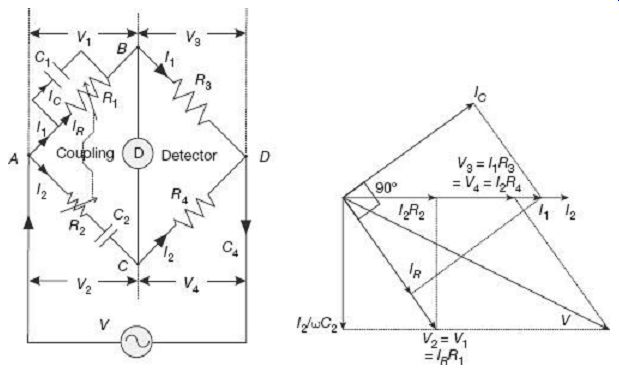
FIG. 13 Wien' s bridge under balanced condition: (a) Configuration (b)
Phasor diagram Under balanced condition, since no current flows through the
detector, nodes B and C are at the same potential, i.e., V1=V2 and V3=V4.
As shown in the phasor diagram of FIG. 13 (b), V3 = I1R3 and V4 = I2R4 being equal both in magnitude and phase, they overlap. Current I1 in the arm BD and I2 flowing through R4 are also in the same phase with I1R3 and I2R4 along the horizontal line. The other resistive drop, namely, I2R2 in the arm AC is also along the same horizontal line. The resistive voltage drop IRR2 across R2 and the quadrature capacitive drop I2/wC2 across C2 will add up to the total voltage drop V2 in the arm AC. Under balanced condition, voltage drops across arms AB and AC are equal, thus V1 = V2 both in magnitude and phase. The voltage V1 will be in the same phase as the voltage drop IRR1 across the resistance R1 in the same arm AB. The resistive current IR will thus be in the same phase as the voltage V1 = IRR1. Phasor addition of the resistive current IR and the quadrature capacitive current IC, which flows through the parallel R1C1 branch, will add up to the total current I1 in the arm AB. Finally, phasor summation of V1 and V3 (or V2 and V4) results in the supply voltage V.
Equating real and imaginary parts, we get
C2R1R4 = C2R2R3 + C1R1R3
... and In most bridges, the parameters are so chosen that, R1 = R2 = R and C1 = C2 = C Then, from Eq. (37), we get Sliders for the resistors R1 and R2 are mechanically coupled to satisfy the criteria R1 = R2.
Wien's bridge is frequency sensitive. Thus, unless the supply voltage is purely sinusoidal, achieving balance may be troublesome, since harmonics may disturb balance condition. Use of filters with the null detector in such cases may solve the problem.
7. WAGNER EARTHING DEVICE
A serious problem encountered in sensitive ac bridge circuits is that due to stray capacitances. Stray capacitances may be formed in an ac bridge between various junction points within the bridge configuration and nearest ground (earthed) object. These stray capacitors affect bridge balance in severe ways since these capacitors carry leakage current when the bridge is operated with ac, especially at high frequencies. Formation of such stray capacitors in a simple ac bridge circuit is schematically shown in FIG. 14.
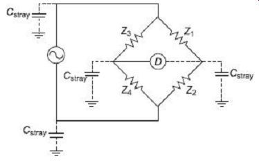
FIG. 14 Formation of stray capacitors in an ac bridge One possible way
of reducing this effect is to keep the detector at ground potential, so there
will be no ac voltage between it and the ground, and thus no current through
FIG. 14
Formation of stray capacitors in an ac bridge the stray capacitances can leak out.
However, directly connecting the null detector to ground is not an option, since it would create a direct current path for other stray currents. Instead, a special voltage-divider circuit, called a Wagner ground or Wagner earth, may be used to maintain the null detector at ground potential without having to make a direct connection between the detector and ground.
The Wagner earth circuit is nothing more than a voltage divider as shown in FIG. 15. There are two additional (auxiliary) arms ZA and ZB in the bridge configuration with a ground connection at their junction E. The switch S is used to connect one end of the detector alternately to the ground point e and the bridge connection point d. The two impedances ZA and ZB must be made of such components (R, L, or C) so that they are capable of forming a balanced bridge with the existing bride arm pairs Z1-Z2 or Z3-Z4.
Stray capacitances formed between bridge junctions and the earthing point E are shown as C1, C2, C3 and C4.
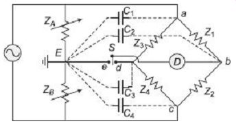
FIG. 15 Wagner earthing device The bridge is first balanced with the
arms Z1-Z2 and Z3-Z4 with the switch at the position d. The switch is next
thrown to position e and balance is once again attained between arms Z1-Z2
and Z5-Z6. The process is repeated till both bridge configurations become
balanced. At this point, potential at the points b, d, e are the same and
are all at earth potential. Thus, the Wagner earthing divider forces the
null detector to be at ground potential, without a direct connection between
the detector and ground. Under these conditions, no current can flow through
the stray capacitors C2 and C3 since their terminals are both at earth potential.
The other two stray capacitors C1 and C4 become part of (shunt to) the Wagner
arms ZA and ZB, and thus get eliminated from the original bridge network.
The Wagner earthing method gives satisfactory results from the point of view of eliminating stray capacitance charging effects in ac bridges, but the entire balancing process is time consuming at times.
QUIZ
Objective Questions
1. A bridge circuit works at a frequency of 2 kHz. Which of the following can be used as null detector in such a bridge? (a) Vibration galvanometers and tunable amplifiers (b) Headphones and tunable amplifiers (c) Vibration galvanometers and headphones (d) All of the above
2. Under balanced condition of a bridge for measuring unknown impedance, if the detector is suddenly taken out (a) measured value of the impedance will be lower (b) measured value of the impedance will be higher (c) measured value of the impedance will not change (d) the impedance can not be measured
3. Harmonic distortions in power supply does not affect the performance of Maxwell's bridge since (a) filters are used to remove harmonics (b) final expression for unknown inductance contain only fundamental frequency (c) mechanical resonance frequency of null detectors are beyond the range of harmonic frequencies (d) final expression for unknown inductance is independent of frequency
4. Maxwell's bridge can be used for measurement of inductance with (a) high Q factors (b) very low Q factors (c) medium Q factors (d) wide range of Q factor variations
5. The advantage of Hay's bridge over Maxwell's inductance-capacitance bridge is that (a) its final balance equations are independent of frequency (b) it reduces cost by not making capacitor or inductor as the variable parameters (c) it can be used measuring low Q inductors (d) it can be used measuring high Q inductors
6. The advantage of Anderson's bridge over Maxwell's bridge is that (a) its final balance equations are independent of inductor losses (b) it reduces cost by not making capacitor or inductor as the variable parameters (c) number of bridge components required are less (d) attaining balance condition is easier and less time consuming
7. The main advantage of Owen's bridge for measurement of unknown inductance is that (a) it has two independent elements R and C for achieving balance (b) it can be used for measurement of very high Q coils (c) it is very inexpensive (d) it can be used for measurement of unknown capacitance as well
8. DeSauty's bridge is used for measurement of (a) high Q inductances (b) low Q inductances (c) loss less capacitors (d) capacitors with dielectric losses
9. Schering bridge can be used for measurement of (a) capacitance and dissipation factor (b) dissipation factor only (c) inductance with inherent loss (d) capacitor but not dissipation factor
10. Frequency can be measured using (a) Anderson's bridge (b) Maxwell's bridge (c) De Sauty's bridge (d) Wien's bridge
Questions
1. Derive the general equations for balance in ac bridges. Show that both magnitude and phase conditions need to be satisfied for balancing an ac bridge.
2. Derive the expression for balance in Maxwell's inductance bridge. Draw the phasor diagram under balanced condition.
3. Show that the final balance expressions are independent of supply frequency in a Maxwell's bridge. What is the advantage in having balance equations independent of frequency?
4. Discuss the advantages and disadvantages of Maxwell's bridge for measurement of unknown inductance.
5. Explain why Maxwell's inductance-capacitance bridge is suitable for measurement of inductors having quality factor in the range 1 to 10.
6. Explain with the help of phasor diagram, how unknown inductance can be measured using Owen's bridge.
7. Explain how Wien's bridge can be used for measurement of unknown frequencies. Derive the expression for frequency in terms of bridge parameters.
More Questions
1. (a) Explain with the help of a phasor diagram, how unknown inductance can be measured using Maxwell's inductance-capacitance bridge. (b) The following data relate to a basic ac bridge:
2. Describe the working of Hay's bridge for measurement of inductance. Derive the equations for balance and draw the phasor diagram under balanced condition. Explain how this bridge is suitable for measurement of high Q chokes?
3. Derive equations for balance for an Anderson's bridge. Draw its phasor diagram under balance. What are its advantages and disadvantages?
4. Describe how unknown capacitors can be measured using De Sauty's bridge. What are the limitations of this bridge and how they can be overcome by using a modified De Sauty's bridge? Draw relevant phasor diagrams
5. Describe the working of a Schering bridge for measurement of capacitance and dissipation factor. Derive relevant equations and draw phasor diagram under balanced condition.
6. In an Anderson's bridge for measurement of inductance, the arm AB consists of an unknown impedance with L and R, the arm BC contains a variable resistor, fixed resistances of 500 O each in arms CD and DA, a known variable resistance in the arm DE, and a capacitor of fixed capacitance 2 µF in the arm CE. The ac supply of 200 Hz is connected across A and C, and the detector is connected between B and E. If balance is obtained with a resistance of 300 O in the arm DE and a resistance of 600 O in the arm BC, calculate values of unknown impedance L and R. Derive the relevant equations for balance and draw the phasor diagram.
7. The four arms of a Maxwell's inductance-capacitance bridge at balance are Arm AB : A choke coil L1 with an equivalent series resistance R1 Arm BC : A non-inductive resistance of 800 O Arm CD : A mica capacitor of 0.3 µF in parallel with a noninductive resistance of 800 O Arm DA : A non-inductive resistance 800 O Supply is given between terminals A and C and the detector is connected between nodes B and D. Derive the equations for balance of the bridge and hence determine values of L1 and R1. Draw the phasor diagram of the bridge under balanced condition.
8. The four arms of a Hay's bridge used for measurement of unknown inductance is configured as follows: Arm AB :
A choke coil of unknown impedance Arm BC : A non-inductive resistance of 1200 O
Arm CD : A non-inductive resistance of 900 O in series with a standard capacitor of 0.4 µF
Arm DA : A noninductive resistance 18000 O
If a supply of 300 V at 50 Hz is given between terminals A and C and the detector is connected between nodes B and D, determine the inductance and inherent resistance of the unknown choke coil. Derive the conditions for balance and draw the phasor diagram under balanced condition.
9. A capacitor busing forms the arm AB of a Schering bridge and a standard capacitor of 400 µF capacitance and negligible loss, form the arm AD. Arm BC consists of a non-inductive resistance of 200 O. When the detector connected between nodes B and D shows no deflection, the arm CD has a resistance of 82.4 O in parallel with a capacitance of 0.124 µF. The supply frequency is 50 Hz. Calculate the capacitance and dielectric loss angle of the capacitor. Derive the equations for balance and draw the relevant phasor diagram at balanced state.
10. (a) An ac bridge is configured as follows:
Arm AB : A resistance of 600 O in parallel with a capacitance of 0.3 µF
Arm BC : An unknown non-inductive resistance
Arm CD : A noninductive resistance of 1000 O
Arm DA : A resistance of 400 O in series with a capacitance of 0.1 µF
If a supply is given between terminals A and C and the detector is connected between nodes B and D, find the resistance required in the arm BC and also the supply frequency for the bridge to be balanced.
(b) Explain how Wien's bridge can be used for measurement of unknown frequency. Draw the phasor diagram under balanced condition and derive the expression for balance.