AMAZON multi-meters discounts AMAZON oscilloscope discounts
1. INTRODUCTION
Measurement of electric power is as essential in industry as in commercial or even domestic applications. Prior estimation and subsequent measurements of instantaneous and peak power demands of any installation are mandatory for design, operation and maintenance of the electric power supply network feeding it. Whereas an under-estimation of power demand may lead to blowing out of power supply side accessories, on the other hand, over-estimation can end up with over-design and additional cost of installation.
Knowledge about accurate estimation, calculation and measurement of electric power is thus of primary concern for designers of new installations. In this section, the most popular power measurement methods and instruments in dc and ac circuits are illustrated.
2. POWER MEASUREMENT IN dc CIRCUITS
Electric power (P) consumed by a load (R) supplied from a dc power supply (VS) is the product of the voltage across the load (VR) and the current flowing through the load (IR):
Thus, power measurement in a dc circuit can be carried out using a voltmeter (V) and an ammeter (A) using any one of the arrangements shown in FIG. 1.
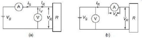
FIG. 1 Two arrangements for power measurement in dc circuits One thing
should be kept in mind while using any of the two measuring arrangements
shown in FIG. 1; that both the voltmeter and the ammeter requires power
for their own operations. In the arrangement of FIG. 1(a), the voltmeter
is connected between the load and the ammeter. The ammeter thus, in this
case measures the current flowing into the voltmeter, in addition to the
current flowing into the load.
Thus,
Power indicated = Power consumed + Power loss in voltmeter
In the arrangement of FIG. 1(b), the voltmeter measures the voltage drop across the ammeter in addition to that dropping across the load.
Thus, Power indicated = Power consumed + Power loss in
Ammeter
Thus, both arrangements indicate the additional power absorbed by the instruments in addition to indicating the true power consumed by the load only. The corresponding measurement errors are generally referred to as insertion errors.
Ideally, in theory, if we consider voltmeters to have infinite internal impedance and ammeters to have zero internal impedance, then from (3) and (5) one can observe that the power consumed by the respective instruments go down to zero. Thus, in ideal cases, both the two arrangements can give correct indication of the power consumed by the load. Under practical conditions, the value of power loss in instruments is quite small, if not totally zero, as compared with the load power, and therefore, the error introduced on this account is small.
Example 1
Two incandescent lamps with 80 ? and 120 ? resistances are connected in series with a 200 V dc source. Find the errors in measurement of power in the 80 ? lamp using a voltmeter with internal resistance of 100 k? and an ammeter with internal resistance of 0.1 m?, when (a) the voltmeter is connected nearer to the lamp than the ammeter , and (b) when the ammeter is connected nearer to the lamp than the voltmeter
Solution
Assuming both the instruments to be ideal, i.e., the voltmeter with infinite internal impedance and ammeter with zero internal impedance, the current through the series circuit should be
= 200/(80 + 120) = 1 A
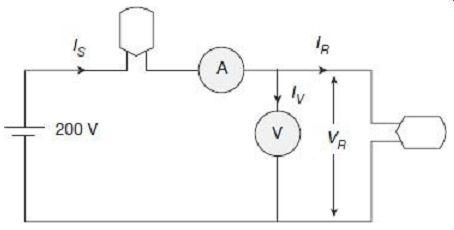
FIG. 2 Actual connections for Example 1(a)
Hence, true power consumed by the 80 ? lamp would have been = 12 X 80 = 80 ?
However, considering the internal resistance of the ammeter and voltmeter, the equivalent circuit will look like FIG. 3.
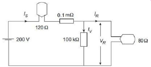
FIG. 3 Equivalent circuit for Example 1(a) Supply current (ammeter
reading)
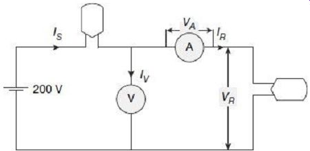
FIG. 4 Actual connection for Example 1(b)
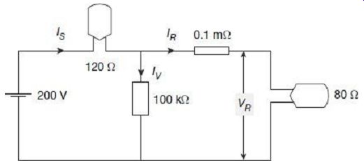
FIG. 5 Equivalent circuit for Example 1(a) Supply current
Thus, we can have the following analysis:
Power in dc circuits can also be measured by wattmeter. Wattmeter can give direct indication of power and there is no need to multiply two readings as in the case when ammeter and voltmeter is used.
The type of wattmeter most commonly used for such power measurement is the dynamometer. It is built by (1) two fixed coils, connected in series and positioned coaxially with space between them, and (2) a moving coil, placed between the fixed coils and fitted with a pointer. Such a construction for a dynamometer-type wattmeter is shown in FIG. 6.
It can be shown that the torque produced in the dynamometer is proportional to the product of the current flowing through the fixed coils times that through the moving coil.
The fixed coils, generally referred to as current coils, carry the load current while the moving coil, generally referred to as voltage coil, carries a current that is proportional, via the multiplier resistor RV , to the voltage across the load resistor R. As a consequence, the deflection of the moving coil is proportional to the power consumed by the load.
A typical connection of such a wattmeter for power measurement in dc circuit is shown in FIG. 7.
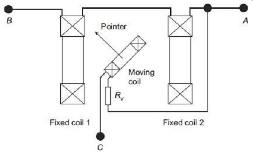
FIG. 6 Basic construction of dynamometer-type wattmeter In such a connection
of the wattmeter, the insertion error, as in the pervious case with ammeter
and voltmeter, still exists. Relative ß positioning of the current coil and
the voltage coil with respect to load, introduce similar VS errors in measurement
of actual power. In particular, by connecting the voltage coil between A
and C (FIG. 7), the current coils carry the surplus current flowing through
the voltage coil. On the other hand, by connecting the moving coil between
B and C, this current error can be avoided, but now the voltage coil measures
the surplus voltage drop across the current coils.
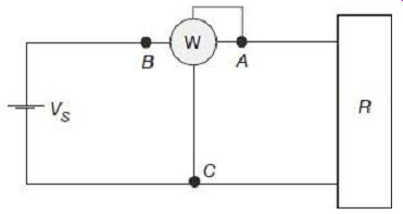
FIG. 7 Connection of dynamometer-type wattmeter for power measurement
in dc circuit
3. POWER MEASUREMENT IN ac CIRCUITS
In alternating current circuits, the instantaneous power varies continuously as the voltage and current varies while going through a cycle. In such a case, the power at any instant is given by where, p(t), v(t), and i(t) are values of instantaneous power, voltage, and current respectively.
Thus, if both voltage and current can be assumed to be sinusoidal, with the current lagging the voltage by phase-angle f, then where, Vm and Im are peak values of voltage and current respectively, and w is the angular frequency.
The instantaneous power pis therefore given by Average value of power over a complete cycle in such a case will be where, V and I are rms values of voltage and current respectively and cos j is power factor of the load.
Involvement of the power-factor term cos j in the expression for power in ac circuit indicates that ac power cannot be measured simply by connecting a pair of ammeter and voltmeter. A wattmeter, with in-built facility for taking in to account the power factor, can only be used for measurement of power in ac circuits.
FIG. 8 plots the waveforms of instantaneous power p(t), voltage v(t), and current respectively.
Thus, if both voltage and current can be assumed to be sinusoidal, with the current lagging the voltage by phase-angle f, then where, Vm and Im are peak values of voltage and current respectively, and w is the angular frequency.
The instantaneous power pis therefore given by Average value of power over a complete cycle in such a case will be where, V and I are rms values of voltage and current respectively and cos j is power factor of the load.
Involvement of the power-factor term cos j in the expression for power in ac circuit indicates that ac power cannot be measured simply by connecting a pair of ammeter and voltmeter. A wattmeter, with in-built facility for taking in to account the power factor, can only be used for measurement of power in ac circuits.
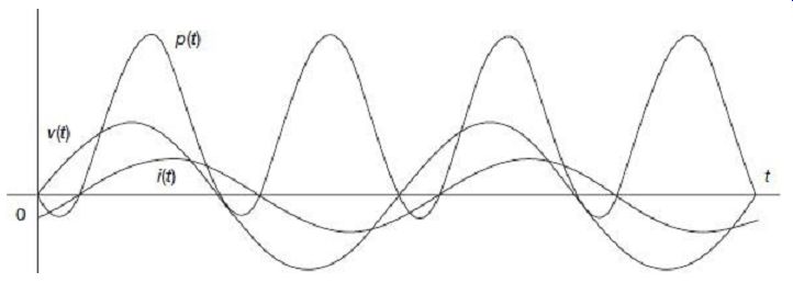
FIG. 8 Plot of the waveforms of instantaneous power voltage and current
in ac circuit Readers may find interesting to note in FIG. 8 that though
voltage and current waveforms have zero average value over a complete
cycle, the instantaneous power has offset above zero having non-zero average
value.
4. ELECTRODYNAMOMETER-TYPE WATTMETER
An electrodynamometer-type wattmeter is similar in design and construction with the analog electrodynamometer-type ammeter and voltmeter described in section 2.
4.1 Construction of Electrodynamometer-type Wattmeter
Schematic diagram displaying the basic constructional features of a electrodynamometer type wattmeter is shown in FIG. 9.
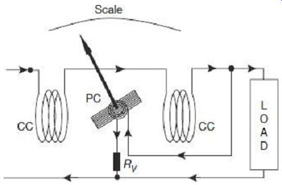
FIG. 9 Schematic of electrodynamometer-type wattmeter Internal view
of such an arrangement is shown in the photograph of FIG. 10.
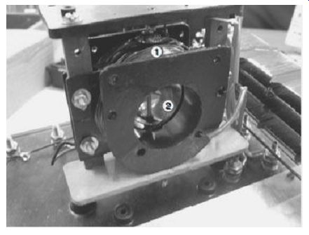
FIG. 10 Internal photograph of electrodynamometer-type wattmeter:(1)
Fixed (current) coil (2) Moving (potential) coil
1. Fixed Coil System
Such an instrument has two coils connected in different ways to the same circuit of which power is to be measured. The fixed coils or the field coils are connected in series with the load so as to carry the same current as the load. The fixed coils are hence, termed as the Current Coils (CC) of the wattmeter. The main magnetic field is produced by these fixed coils. This coil is divided in two sections so as to provide more uniform magnetic field near the center and to allow placement of the instrument moving shaft.
Fixed coils are usually wound with thick wires for carrying the main load current through them. Windings of the fixed coil is normally made of stranded conductors running together but, insulated from each other. All the strands are brought out to an external commutating terminator so that a number of current ranges of the instrument may be obtained by grouping them all in series, all in parallel, or in a series-parallel combination.
Such stranding of the fixed coils also reduces Eddy-current loss in the conductors. Still higher current or voltage ranges, however, can be accommodated only through the use of instrument transformers.
Fixed coils are mounted rigidly with the coil supporting structures to prevent any small movement whatsoever and resulting field distortions. Mounting supports are made of ceramic, and not metal, so as not to disturb the magnetic field distribution.
2. Moving Coil System
The moving coil that is connected across the load carries a current proportional to the voltage. Since the moving coil carries a current proportional to the voltage, it is called the voltage coil or the pressure coil or simply PC of the wattmeter. The moving coil is entirely embraced by the pair of fixed coils. A high value non-inductive resistance is connected in series with the voltage coil to restrict the current through it to a small value, and also to ensure that voltage coil current remains as far as possible in phase with the load voltage.
The moving coil, made of fine wires, is wound either as a self-sustaining air-cored coil, or else wound on a nonmetallic former. A metallic former, otherwise would induce Eddy currents in them under influence of the alternating field.
3. Movement and Restoring System
The moving, or voltage coil along with the pointer is mounted on an aluminum spindle in case jewel bearings are used to support the spindle. For higher sensitivity requirements, the moving coil may be suspended from a torsion head by a metallic suspension which serves as a lead to the coil. In other constructions, the coil may be suspended by a silk fiber together with a spiral spring which gives the required torsion. The phosphor-bronze springs are also used to lead current into and out of the moving coil. In any case, the torsion head with suspension, or the spring, also serves the purpose of providing the restoring torque to bring the pointer back to its initial position once measurement is over.
The moving, or voltage coil current must be limited to much low values keeping in mind the design requirements of the movement system. Current is lead to and out of the moving coil through two spiral springs. Current value in the moving coil is thus to be limited to values that can be safely carried by the springs without appreciable heating being caused.
4. Damping System
Damping in such instruments may be provided by small aluminum vanes attached at the bottom of the spindle. These vanes are made to move inside enclosed air chambers, thereby creating the damping torque. In other cases, the moving coil itself can be stitched on a thin sheet of mica, which acts as the damping vane while movements. Eddy-current damping, however, cannot be used with these instruments. This is due to the fact that any metallic element to be used for Eddy-current damping will interfere and distort the otherwise weak operating magnetic field. Moreover, introduction of any external permanent magnet for the purpose of Eddy-current damping will severely hamper the operating magnetic field.
5. Shielding System
The operating field produced by the fixed coils, is comparatively lower in electrodynamometer-type instruments as compared to other type of instruments. In some cases, even the earth's magnetic field can pollute the measurement readings. It is thus essential to shield the electrodynamometer-type instruments from effects of external magnetic fields. Enclosures of such instruments are thus made of alloys with high permeability to restrict penetration of external stray magnetic fields into the instrument.
4.2 Operation of Electrodynamometer-type Wattmeter
The schematic operational circuit of an electrodynamometer-type wattmeter being used for measurement of power in a circuit is shown in FIG. 11.
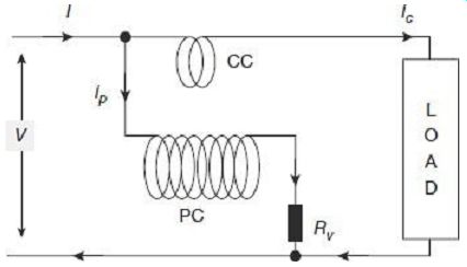
FIG. 11 Operational circuit of electrodynamometer-type wattmeter V =
voltage to be measured (rms) I = current to be measured (rms) iP = voltage
(pressure) coil instantaneous current iC = current coil instantaneous current
RV = external resistance connected with pressure coil RP = resistance of
pressure coil circuit (PC resistance + RV) M = mutual inductance between
current coil and pressure coil
? = angle of deflection of the moving system
? = angular frequency of supply in radians per second
f = phase-angle lag of current I with respect to voltage V
As described in section 2, the instantaneous torque of the electrodynamometer wattmeter shown in FIG. 11 is given by Instantaneous value of voltage across the pressure-coil circuit is If the pressure coil resistance can be assumed to be very high, the whole pressure coil can be assumed to be behaving like a resistance only. The current iP in the pressure coil thus, can be assumed to in phase with the voltage vP, and its instantaneous value is where IP = V/RP is the rms value of current in pressure coil.
Assuming that the pressure-coil resistance is sufficiently high to prevent branching out of any portion of the supply current towards the pressure coil, the current coil current can be written as Thus, instantaneous torque from (9) can be written as
Presence of the term containing 2w t, indicates the instantaneous torque as shown in (10) varies at twice the frequency of voltage and current.
Average deflecting torque over a complete cycle is With a spring constant K, the controlling torque provided by the spring for a final steady-state deflection of ? is given by TC = K? Under steady-state condition, the average deflecting torque will be balanced by the controlling torque provided by the spring. Thus, at balanced condition TC = Td where, P is the power to be measured and K1 = 1/KRP is a constant.
Steady-state deflection ? is thus found to be an indication of the power P to be measured.
4.3 Shape of scale in Electrodynamometer-type Wattmeter
Steady-state deflection ? can be made proportional to the power P to be measured, i.e., the deflection will vary linearly with variation in power if the rate of change of mutual inductance is constant over the range of deflection. In other words, the scale of measurement will be uniform if the mutual inductance between the fixed and moving coils varies linearly with angle of deflection. Such a variation in mutual inductance can be achieved by careful design of the instrument. FIG. 12 shows the expected nature of variation of mutual inductance between fixed and moving coils with respect to angle of deflection.
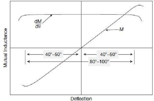
FIG. 12 Variation of mutual inductance with deflection
By a suitable design, the mutual inductance between fixed and moving coils can be made to vary linearly with deflection angle over a range of 40° to 50° on either side of zero mutual inductance position, as shown in FIG. 12. If the position of zero mutual inductance can be kept at the mid-scale, then the scale can be graduated to be uniform over 80° to 100°, which covers almost entire range of the scale.
4.4 Errors in Electrodynamometer-type Wattmeter
1. Error due to Pressure-Coil Inductance
It was assumed during the discussions so far that the pressure coil circuit is purely resistive. In reality, however, the pressure coil will have certain inductance along with resistance. This will introduce errors in measurement unless necessary compensations are taken care of. To have an estimate of such error, let us consider the following:
V = voltage applied to the pressure coil circuit (rms)
I = current in the current coil circuit (rms)
IP = current in the voltage (pressure) coil circuit (rms)
rP = resistance of pressure coil only
L = inductance of pressure coil
RV = external resistance connected with pressure coil
RP = resistance of pressure coil circuit (PC resistance + RV)
ZP = impedance of pressure coil circuit
M = mutual inductance between current coil and pressure coil
? = angular frequency of supply in radian per second
f = phase-angle lag of current I with respect to voltage V
Due to inherent inductance of the pressure coil circuit, the current and voltage in the pressure coil will no longer be in phase, rather the current through the pressure coil will lag the voltage across it by a certain angle given by As can be seen from FIG. 13, current through the pressure coil lags voltage across it by a phase-angle which is less than that between the current coil current and the pressure coil voltage.
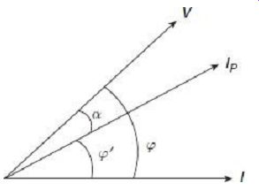
FIG. 13 Wattmeter phasor diagram with pressure coil inductance
In such a case, phase-angle difference between the with pressure coil inductance pressure coil current and current coil current is…
Following from (11), the wattmeter deflection will be…
Relating to RP = ZP cos a in the pressure coil circuit, the wattmeter deflection can be re-written as
VI dM
In the absence of inductance, ZP = RP and a = 0; wattmeter in that case will read true power, given by, Taking the ratio of true power indication to actual wattmeter reading, we get…
True power indication can thus be obtained from the actual wattmeter reading using the correction factor CF as
True power indication = CF X
Actual wattmeter reading Thus, for lagging power factor loads, s
The above relations, along with FIG. 13 indicate that under lagging power factor loads, unless special precautions are taken, actual wattmeter reading will tend to display higher values as compared to true power consumed.
For leading power factor loads, however, the wattmeter phasor diagram will be as shown in FIG. 14.
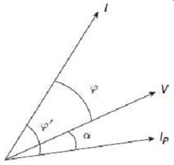
FIG. 14 Wattmeter phasor diagram with pressure coil inductance during
leading load.
For leading power factor loads, s The above relations, along with FIG. 13 indicate that under leading power factor loads, unless special precautions are taken, actual wattmeter reading will tend to display higher values as compared to true power consumed.
2. Compensation for Pressure Coil Inductance
A wattmeter can be compensated for pressure coil inductance by connecting a preset value of capacitance across a certain portion of the external resistance connected in series with the pressure coil, as shown in FIG. 15.
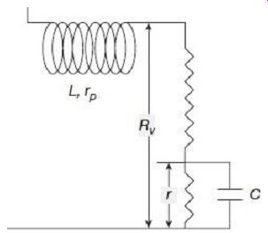
FIG. 15 Compensation for pressure coil inductance
The total impedance of the circuit in such a case can be written as
To make the entire circuit behave as purely resistive, if we can design the circuit parameters in such a case that for power frequencies
w2C 2r2 << 1
Then we can re-write the total impedance of the pressure coil as
ZP = (rp + RV - r) + jwL + r - jwCr2 = rP + RV + jw(L - Cr2)
If by proper design, we can make L = Cr2
Then, impedance = rp + RV = RP
Thus error introduced due pressure coil inductance can be substantially eliminated.
3. Error due to Pressure Coil Capacitance
The voltage, or pressure coil circuit may have inherent capacitance in addition to inductance. This capacitance effect is mainly due to inter-turn capacitance of the winding and external series resistance. The effect of stray capacitance of the pressure coil is opposite to that due to inductance. Therefore, the wattmeter reads low on lagging power factors and high on leading power factors of the load. Actual reading of the wattmeter, thus, once again needs to be corrected by the corresponding correction factors to obtain the true reading. The effect of capacitance (as well as inductance) varies with variable frequency of the supply.
4. Error due to Connection
There are two alternate methods of connection of wattmeter to the circuit for measurement of power. These are shown in FIG. 16. In either of these connection modes, errors are introduced in measurement due power losses in pressure coil and current coil.
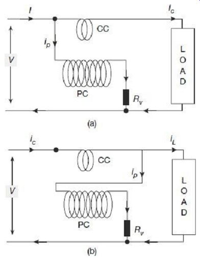
FIG. 16 Wattmeter connections In the connection of FIG. 16(a), the
pressure coil is connected across the supply, thus pressure coil measures
the voltage across the load, plus the voltage drop across the current coil.
Wattmeter reading in this case will thus include power loss in current coil
as well, along with power consumed by the load.
Wattmeter reading = Power consumed by load + Power loss in CC
In the connection of FIG. 16(b), the current coil is connected to the supply side;
therefore, it carries load current plus the pressure coil current. Hence, wattmeter reading in this case includes, along with power consumed by the load, power loss in the pressure coil as well.
Wattmeter reading = Power consumed by load + Power loss in PC
In the case when load current is small, power loss in the current coil is small and hence the connection of FIG. 16(a) will introduce comparatively less error in measurement.
On the other hand, when load current is large, current branching through the pressure coil is relatively small and error in measurement will be less if connection of FIG. 16(b) is used.
Errors due to branching out of current through the pressure coil can be minimized by the use of compensating coil as schematically shown in FIG. 17.
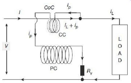
FIG. 17 Schematic connection diagram of compensated wattmeter
In the compensated connection, the current coil consists of two windings, each winding having the same number of turns. The two windings are made as far as possible identical and coincident. One of the two windings (CC) is made of heavy wire that carries the load current plus the current for the pressure coil. The other winding (compensating coil-CoC) which is connected in series with the pressure coil, uses thin wire and carries only the current to the pressure coil. This current in the compensating coil is, however, in a direction opposite to the current in main current coil, creating a flux that opposes the main flux. The resultant magnetic field is thus due to the current coil only, effects of pressure coil current on the current coil flux mutually nullifying each other. Thus, error due to pressure coil current flowing in the current coil in cancelled out and the wattmeter indicates correct power.
5. Eddy-current Errors
Unless adequate precautions are adopted, Eddy-currents may be induced in metallic parts of the instrument and even within the thickness of the conductors by alternating magnetic field of the current coil. These Eddy-currents produce spurious magnetic fields of their own and distort the magnitude and phase of the main current coil magnetic field, thereby introducing error in measurement of power.
Error caused by Eddy-currents is not easy to estimate, and may become objectionable if metal parts are not carefully avoided from near the current coil. In fact, solid metal in coil supports and structural part should be kept to a minimum as far as practicable. Any metal that is used is kept away and is selected to have high resistivity so as to reduce Eddy currents induced in it. Stranded conductors are recommended for the current coil to restrict generation of Eddy-current within the thickness of the conductor.
6. Stray Magnetic Field Errors
The operating field in electrodynamometer-type instruments being weak, special care must be taken to protect these instruments from external magnetic fields. Hence, these instruments should be shielded against effects of stray magnetic fields. Laminated iron shields are used in portable laboratory instruments, while steel casings are provided as shields in switchboard mounted wattmeter. Precision wattmeters, however, are not provided with metals shields, for that will introduce errors due to Eddy-current, and also some dc error due to permanent magnetization of the metal shield under influence of external magnetic field. Such wattmeters are manufactured to have a static system as shown in Figure
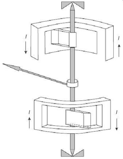
FIG. 18 Astatic systems for electrodynamometer wattmeter Astatic electrodynamometer
instruments are constructed with two similar sets of fixed and moving coils
mounted on the same shaft. The pair of fixed coils is so connected that their
magnetic fields are in opposition. Similarly, the pair of moving coils is
also connected to produce magnetic fields in opposite directions. This makes
the deflecting torque acting on the two moving coils to be in the same direction.
Deflection of the pointer is thus due to additive action of the two moving
coils. However, since the two fields in the two pairs of fixed and moving
coils are in opposition, any external uniform field will affect the two sets
of pairs differently. The external field will reduce the field in one coil
and will enhance the field in the other coil by identical amount. Therefore,
the deflecting torque produced by one coil is increased and that by the other
coil is reduced by an] equal amount. This makes the net torque on account
of the external magnetic field to zero.
7. Error Caused by Vibration of the Moving System
The instantaneous torque on the moving system varies cyclically at twice the frequency of the voltage and current (10). If any part of the moving system, such as the spring or the pointer has natural frequency close to that of torque pulsation, then accidental resonance may take place. In such a case, the moving system may vibrate with considerable amplitude. These vibrations may pose problems while noting the pointer position on the scale. These errors due to vibrations may be avoided by designing the moving elements to have natural frequencies much further away from twice the frequency of the supply voltage.
8. Temperature Errors
Temperature changes may affect accuracy of wattmeter by altering the coil resistances.
Temperature my change due to change in room temperature or even due to heating effects in conductors with flow of current. Change in temperature also affects the spring stiffness, thereby introducing error in the deflection process. High-precision instruments are fitted with temperature compensating resistors that tend to neutralize the effects of temperature variation.
5. INDUCTION-TYPE WATTMETER
Induction-type wattmeters work in similar principles as for induction type ammeters and voltmeters previously discussed in section 2. Induction-type wattmeters, however, following the very basic principles of mutual induction, can only be used for measurement of ac power, in contrast to electrodynamometer type wattmeters that can be used for power measurements in both ac and dc circuits. Induction type wattmeters, in contradiction to electrodynamometer-type wattmeters, can be used only with circuits having relatively steady values of frequency and voltage.
5.1 Construction of Induction-type Wattmeter
Schematic diagram displaying the basic constructional features of an induction-type wattmeter is shown in FIG. 19.
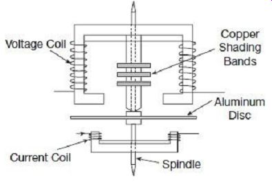
FIG. 19 Constructional details of induction-type wattmeter
Induction-type wattmeters have two laminated iron-core electromagnets. One of the electromagnets is excited by the load current, and the other by a current proportional to the voltage of the circuit in which the power is to be measured. The upper magnet in FIG. 19, which is connected across the voltage to be measured, is named as the shunt magnet, whereas the other electromagnet connected in series with the load to carry load current is called the series magnet. A thin aluminum disc, mounted in the space between the two magnets is acted upon by a combined effect of fluxes coming out of these two electromagnets. In ac circuits, interaction of these changing fluxes will induce Eddy current within the aluminum disc.
The two voltage coils, connected in series, are wound in such a way that both of them send flux through the central limb. Copper shading bands fitted on the central limb of the shunt magnet makes the flux coming out of the magnet lag behind the applied voltage by 90°.
The series magnet houses two small current coils in series. These are wound in a way that the fluxes they create within the core of the magnet are in the same direction.
5.2 Operation of Induction-type Wattmeter
A simplified phasor diagram for describing the theory of operation of induction-type wattmeter is shown in FIG. 20.
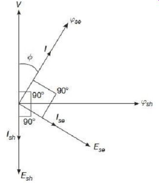
FIG. 20 Phasor diagram for induction-type wattmeter V = voltage to be
measured I = current to be measured f = phase-angle lag of current I with
respect to voltage V fsh = flux of the shunt magnet
fse = flux of the series magnet
Esh = eddy emf induced in the disc by the flux jsh of shunt magnet Ish = eddy-current fl owing in the disc due to and in phase with Esh (neglecting inductance of the Eddy-current path) Ese = eddy emf induced in the disc by the flux jse of series magnet Ise = eddy-current fl owing in the disc due to and in phase with Ese (neglecting inductance of the Eddy-current path) Z = impedance of the Eddy-current path
? = angular frequency of supply in radians per second Td = average torque acting on the disc
The shunt magnet flux fsh is made to lag behind the applied voltage (V ) by 90°.
This is achieved by the use of copper shading rings. On the other hand, the series magnet flux fse is in the same phase as the load current (I ) through it.
Continuing from theories of induction-type instruments in section 2, the instantaneous torque acting on the aluminum disc is proportional to (fsh · ise - fse · ish).
Let, instantaneous value the applied voltage is v = Vm sin w t Then, the instantaneous current is given by i = Im sin (w t - j) The shunt magnet flux generated is where k¢ is a constant and the minus (-) sign indicating the fact the flux fsh lags behind the voltage by 90°.
The series magnet flux generated is where k is another constant.
The eddy emf induced in the disc due to the shunt magnet flux is
The resultant eddy-current fl owing in the disc is where ais the phase-angle of the eddy path impedance (Z).
Similarly, the eddy emf induced in the disc due to the series magnet flux is The resultant Eddy-current flowing in the disc is ZThe instantaneous deflecting torque (T) acting on the disc can now be calculated as The average torque acting on the disc is thus where, V and I are rms values of voltage and current. Average torque on the instrument is thus found to be proportional to the power in the circuit.
5.3 Differences Between Dynamometer Wattmeter and Induction-type Wattmeters
Though both electrodynamometer and induction type wattmeters can be used for measurement of power, following are the differences between the two.
6. POWER MEASUREMENT IN POLYPHASE SYSTEMS
Blondel's Theorem
The theorem states that 'in an n-phase network, the total power can be obtained by taking summation of the n wattmeters so connected that current elements of the wattmeters are each in one of the n lines and the corresponding voltage element is connected between that line and a common point'.
Consider the case of measuring power using three wattmeters in a 3-phase, 3-wire system as shown
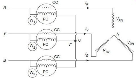
FIG. 21 Power measurement in a 3-phase 3-wire system Current coils of
the three wattmeters, W1, W2 and W3 are connected to the three lines R, Y,
and B. Potential coils of the three wattmeters are connected to the common
point C. The potential at the point C may be different from the neutral point
(N ) potential of load.
Power consumed by the load Reading of wattmeter W1, P1 = VRC X IR Reading of wattmeter W2, P2 = VYC X IY Reading of wattmeter W3, P3 = VBC X IB Now, if the voltage difference between the nodes C and N is taken as VCN = VC - VN, then we can have VRN = VR - VN = VR - VC + VC - VN = VRC + VCN VYN = VY - VN = VY - VC + VC - VN = VYC + VCN VBN = VB - VN = VB - VC + VC - VN = VBC + VCN Sum of the three wattmeter readings can now be combined as P1 + P2 + P3 = (VRN - VCN) X IR + (VYN - VCN) X IY + (VBN - VCN) X IB = VRN X IR + VYN X IY + VBN X IB - VCN (IR + IY + IB) Applying Kirchhoff's current law at node N, (IR + IY + IB) = 0 Thus, sum of wattmeter readings, Comparing with Eq. (22), it is observed that sum of the three individual wattmeter readings indicate the total power consumed by the load.
7. POWER MEASUREMENT IN THREE-PHASE SYSTEMS
7.1 Three-Wattmeter Method
1. Three-Phase Three-Wire Systems
Measurement of power in a 3-phase 3-wire system using three wattmeters has already been described in Section 6.1.
2. Three-Phase Four-Wire Systems
Wattmeter connections for measurement of power in a 3-phase 4-wire system are shown in FIG. 22.
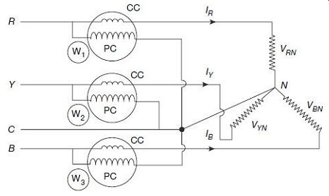
FIG. 22 Power measurement in 3-phase 4-wire system In this case, the
common point of the three pressure coils coincides with the neutral N of
the system. Voltage across each potential coil is thus, effectively the per-phase
voltages of the corresponding phases. Current through current coils of the
three wattmeters are nothing but the phase currents of the corresponding
phases.
Sum of the three wattmeter readings in such a case will be
P1 + P2 + P3 = VRN X IR + VYN X IY + VBN X IB
This is exactly the same as the power consumed by the load.
Hence, summation of the three wattmeter readings display the total power consumed by the load.
7.2 Two-Wattmeter Method
This is the most common method of measuring three-phase power. It is particularly useful when the load is unbalanced.
1. Star-Connected System The connections for measurement of power in the case of a star-connected three-phase load are shown
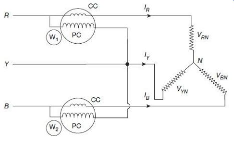
FIG. 23 Two-wattmeter method for star-connected load The current coils
of the wattmeters are connected in lines R and B, and their voltage coils
are connected between lines R and Y, and B and Y respectively.
Power consumed by the load Reading of wattmeter
W1, P1 = VRY X IR = (VRN - VYN) X IR
Reading of wattmeter W2, P2 = VBY X IB = (VBN - VYN) X IB Summation of the two wattmeter readings:
= P1 + P2 = (VRN - VYN) X IR + (VBN - VYN) X IB
From Kirchhoff's law, summation of currents at node N must be zero, i.e., IR + IY + IB = 0 or IR + IB = -IY
Thus, from Eq. (25), we can re-write, It can thus, be concluded that sum of the two wattmeter readings is equal to the total power consumed by the load. This is irrespective of fact whether the load is balanced or not.
2. Delta-Connected System
Two wattmeters can also be used for measurement of total power in a three-phase delta connected system. The connections in the case of a delta-connected three-phase load are shown in FIG. 24.
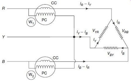
FIG. 24 Two-wattmeter method for delta-connected load The current coils
of the wattmeters are connected in lines R and B, and their voltage coils
are connected between lines R and Y, and B and Y respectively.
Power consumed by the load
Reading of wattmeter
W1, P1 = -VYR X (iR - iY)
Reading of wattmeter
W2, P2 = VBY X (iB - iR)
Summation of the two-wattmeter readings:
= P1 + P2 = -VYR X (iR - iY) + VBY X (iB - iR)
From Kirchhoff's voltage law, summation of voltage drops across a closed loop is zero, i.e.,
VYR + VBY + VRB = 0 or VYR + VBY = -VRB
Thus, from Eq. (28) we can re-write, Therefore, sum of the two wattmeter readings is equal to the total power consumed by the load. This is once again, irrespective of fact whether the load is balanced or not.
3. Effect of Power Factor on Wattmeter Readings
Phasor diagram for the star-connected load of FIG. 23 with a balanced load is shown in FIG. 25.
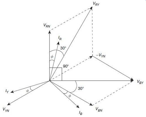
FIG. 25 Phasor diagram for balanced three-phase star-connected load
Let, VRN, VBN, and VYN are phase voltages and IR, IB, and IY are phase currents
for the balanced three phase star-connected system under study.
For a balanced system, phase voltages, VRN = VBN = VYN = V (say)
And, phase currents, IR = IB = IY = I (say)
For a star-connected system,
Line voltages VRY = VYB = VBR = v3 V
Line currents IR = IB = IY = I
Power factor = cos ?, where ? is the angle by which each of the phase currents lag the corresponding phase voltages.
Current through the CC of wattmeter W1 is IR and voltage across its potential coil is VRY. The current IR leads the voltage by VRY an angle (30° - ?), as shown in FIG. 25.
? reading of wattmeter W1 is, Current through the CC of wattmeter W2 is IB and voltage across its potential coil is VBY. The current IB lags the voltage by VBY an angle (30° + ?), as shown in FIG. 25.
? reading of wattmeter W2 is,
Sum of these two-wattmeter readings:
This is the total power consumed by the load, adding together the three individual phases.
Thus, at any power factor, the total power consumed by the load will be, in any case, summation of the two wattmeter readings.
There is way to find out value of the load power factor, if unknown, by a few steps of manipulation.
Using Eq. (30) and Eq. (31), difference of the two wattmeter readings:
Taking the ratio Eq. (33) to Eq. (32), one can have,
4. Unity Power Factor
Thus, at unity power factor, readings of the two wattmeters are equal; each wattmeter reads half the total power.
5. 0.5 Power Factor
Thus, summation of the two wattmeter readings which is same as the 22 total power.
Therefore, at 0.5 power factor, one of the wattmeters reads zero, and the other reads total power.
6. Zero Power Factor
Thus, summation of two-wattmeter readings which is same as the total power.
Therefore, at zero power factor, readings of the two wattmeters are equal but of opposite sign.
It should be noted from the above discussions that, at power factors below 0.5, one of the wattmeters would tend to give negative readings. FIG. 26 plots the nature of variations in the two wattmeter readings with changing power factor. However, in many cases, meter scales are not marked on the negative side, and hence negative readings cannot be recorded. In such a case, either the current or the pressure coil needs to be reversed; such that the meter reads along positive scale. This positive reading, however, should be taken with a negative sign for calculation of total power.
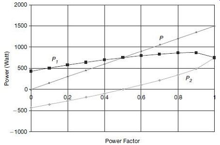
FIG. 26 Variation of two wattmeter readings (P1 and P2) in comparison
to the total power (P) with respect to changing power factor; load is assumed
to be 5 A at 100 V
8. REACTIVE POWER MEASUREMENTS
If V and I are the rms values of the voltage and current in a single-phase circuit and F is the phase-angle difference between them, then the active power in the circuit is, VI cos F.
The active power is obtained by multiplying the voltage by the component of current which is in same phase with the voltage (i.e., I cos F). The component of current which is 90° out of phase with the voltage (i.e., I sin F) is called the reactive component of current and the product VI sin F is called the reactive power. Measurement of reactive power, along with active power is sometimes important, since the phase-angle F of the circuit can be obtained from the ratio (reactive power)/(active power).
The same wattmeter that is used for measurement of active power can also be used for measurement of reactive power with slight modifications in the connections. Observing the fact that sin F = cos (90° -F), the wattmeter may be so connected that the current coil carries the load current and the voltage coil should have a voltage that is 90° out of phase with the actual voltage of the circuit. Under these circumstances, the wattmeter will read VI cos (90° F), or VI sin F For single-phase measurements, the pressure coil circuit may be made to behave as large inductive by inclusion of external inductors in series with it. This will cause the pressure coil current to lag behind the voltage by 90°, and thus the wattmeter will read
VI cos (90° - F) = VI sin F = Reactive power
For measurement of reactive power in a circuit with a balanced 3-phase load, a single wattmeter may be used with suitable connections as shown in FIG. 27, the corresponding phasor diagram is drawn in FIG. 28.

FIG. 27 Connection diagram for reactive power measurement The phasor
IB represents the current flowing through the CC of the wattmeter. The voltage
applied across the voltage coil is the voltage difference between the lines
R and Y, i.e., the difference between the phasors VRN and VYN, i.e., the
phasor VRY. The phase-angle between VRY and -VYN is 30°, for the balanced
system, and that between -VYN and VBN is 60°. Thus, the total phase-angle
difference between VRY and VBN is 90°, and the angle between VRY and IB is
(90° + F). The wattmeter will read where, V is the per phase rms voltage
and I is the line current of the system.
The total reactive power of the circuit is thus:
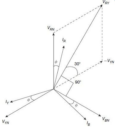
FIG. 28 Phasor diagram for reactive power measurement
9. POWER MEASUREMENT WITH INSTRUMENT TRANSFORMERS
Power measurements in high-voltage, high-current circuits can be effectively done by the use of Potential Transformers (PT) and Current Transformers (CT) in conjunction with conventional wattmeters. By using a number of current transformers of different ratio for the current coil, and a number of potential transformers with different turns ratio for the voltage coil, the same wattmeter can be utilized for power measurements over a wide range.
Primary winding of the CT is connected in series with the load and the secondary winding is connected with the wattmeter current coil, often with an ammeter in between.
Primary winding of the PT is connected across the main power supply lines, and its secondary winding is connected in parallel with the wattmeter voltage coil.
The connections of a wattmeter when so used are shown in FIG. 29, an ammeter and a voltmeter is also connected in the circuit.
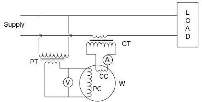
FIG. 29 Power measurement using instrument transformers.
PT and CT are, however, unless carefully designed and compensated, have inherent ratio and phase-angle errors. Ratio errors are more severe for ammeters and voltmeters, where phase-angle errors have more pronounced effects on power measurements. Unless properly compensated for, these can lead to substantial errors in power measurements.
Error introduced in power measurement due to ratio errors in PT and CT can be explained with the help of phasor diagrams of current and voltage in load and also in wattmeter coils, as shown in FIG. 30. FIG. 30(a) refers to a load with lagging power factor, and FIG. 30(b) to a load with leading power factor.
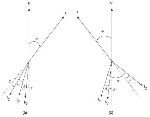
FIG. 30 Phasor diagram showing phase-angle error during power measurement
using instrument transformers for (a) lagging load, and (b) leading load
V = voltage across the load
I = load current
F = load phase-angle between V and I
VP = voltage across secondary wining of PT
Voltage across PC of Wattmeter IP = current through the PC
ß = phase-angle lag between current IP and voltage VP due to inductance of the PC IC = secondary current of CT
Current through CC of wattmeter
a = phase-angle difference the currents in CC and PC of wattmeter d = phase-angle error of PT, i.e., the deviation from secondary being exactly 180° out of phase with
Respect to primary ? = phase-angle error of CT, i.e., the deviation from secondary being exactly 180° out of phase with respect to primary
The Phasor shown with dotted lines are images of V and I with 180° phase shift.
1. Lagging Power Factor
In general, phase-angle (? ) of CT is positive, whereas phase-angle of PT (d) may be positive or negative.
Thus, phase-angle of the load is F = ? + a + ß ± d 2.
Leading Power Factor
Phase-angle of the load is F = a - ? - ß ± d 3.
Correction Factors
For the time being, neglecting the ratio error, the correction factor that need to be incorporated for lagging power factor load is...
For leading power factor, the correction factor is ...
Considering ratio errors for both PT and CT, the corresponding correction factors for ratio errors also need to be incorporated.
General expression for the power to be measured can now be written as Power = K x Actual PT ratio x Actual CT ratio x Wattmeter reading
QUIZ
Objective Questions
1. Power consumed by a simple dc circuit can be measured with the help of a single ammeter if (a) the load resistance is known (b) the supply voltage is known (c) both of (a) and (b) known (d) cannot be measured
2. Power indicated while measuring power in a dc circuit using an ammeter and a voltmeter, when the voltmeter is connected to the load side, is (a) true power consumed by the load (b) power consumed by the load plus power lost in ammeter (c) power consumed by the load plus power lost in voltmeter (d) power consumed by load plus power lost in both ammeter and voltmeter
3. In ammeter-voltmeter method for measurement of power in dc circuits, true power will be obtained with ammeter connected to the load side when (a) voltmeter has zero internal impedance (b) ammeter has zero internal impedance (c) ammeter has infinite internal impedance (d) voltmeter has infinite internal impedance
4. Electrodynamometer-type wattmeters have a construction where (a) current coil is fixed (b) voltage coil is fixed (c) both voltage and current coils are movable (d) both voltage and current coils are fixed
5. In electrodynamometer-type wattmeters, current coil is made of two sections (a) to reduce power loss (b) to produce uniform magnetic field (c) to prevent Eddy-current loss (d) to reduce errors due to stray magnetic field
6. In electrodynamometer-type wattmeters, current coils carrying heavy currents are made of stranded wire (a) to reduce iron loss (b) to reduce Eddy-current loss in conductor (c) to reduce hysteresis loss (d) all of the above
7. In electrodynamometer-type wattmeters, a high value noninductive resistance is connected in series with the pressure coil (a) to prevent overheating of the spring leading current in the pressure coil (b) to restrict the current in the pressure coil (c) to improve power factor of the pressure coil (d) all of the above
8. In electrodynamometer-type wattmeters, both current coil and pressure coil are preferably air-cored (a) to reduce effects of stray magnetic field (b) to reduce Eddy-current losses under AC operation (c) to increase the deflecting torque (d) all of the above
9. In electrodynamometer-type wattmeters, pressure coil inductance produce error which is (a) constant irrespective of load power factor (b) higher at low power factors of load (c) lower at low power factors of load (d) same at lagging and leading power factors of load
10. When measuring power in a circuit with low current, the wattmeter current coil should be connected (a) to the load side (b) to the source side (c) anywhere, either load side or source side, does not matter (d) in series with the load along with CT for current amplification
11. When measuring power in a circuit with high current (a) current coil should be connected to the load side (b) pressure coil should be connected to the load side (c) pressure coil should be connected to the source side (d) the placement of pressure and current coils are immaterial
12. In induction-type wattmeters, (a) voltage coil is the moving coil (b) current coil is the moving coil (c) both are moving (d) none are moving
13. Three wattmeters are used to measure power in a 3-phase balanced star connected load. (a) The reading will be higher when the neutral point is used as the common point for wattmeter pressure coils. (b) The reading will be lower when the neutral point is used as the common point for wattmeter pressure coils. (c) Wattmeter reading will remain unchanged irrespective whether the neutral is used for measurement or not. (d) The three-wattmeter method cannot be used in systems with 4 wires.
14. Two wattmeters can be used to measure power in a (a) three-phase four-wire balanced load (b) three-phase four-wire unbalanced load (c) three-phase three-wire unbalanced load (d) all of the above
15. In 2-wattmeter method for measurement of power in a star-connected 3 phase load, magnitude of the two wattmeter readings will be equal (a) at zero power factor (b) at unity power factor (c) at 0.5 power factor (d) readings of the two wattmeters will never be equal
Questions
1. Draw and label the different internal parts of an electrodynamometer-type wattmeter. What are the special constructional features of the fixed and the moving coils in such an instrument?
2. Discuss about the special shielding requirements and measures taken for shielding internal parts of an electrodynamometer-type wattmeter against external stray magnetic fields.
3. Draw and explain the operation of a compensated wattmeter used to reduce errors due to connection of pressure coil nearer to the load side as pertinent to electrodynamometer-type wattmeters.
4. Draw and explain the constructional features of an induction-type wattmeter used for measurement of power.
5. Draw the schematic and derive how three-phase power consumed by a delta-connected load can be measured by two wattmeters.
6. Explain how power factor of an unknown three-phase load can be estimated by using two wattmeters.
7. Two wattmeters are connected to measure the power consumed by a 3-phase load with a power factor of 0.35.
Total power consumed by the load, as indicated by the two wattmeters, is 70 kW. Find the individual wattmeter readings.
8. With the help of suitable diagrams and sketches, explain how a single wattmeter can be used for measurement of reactive power in a 3-phase balanced system.
9. Derive an expression for the correction factor necessary to be incorporated in wattmeter readings to rectify phase angle error in instrument transformers while used for measurement of power.
More Questions
1. Describe the constructional details of an electrodynamometer-type wattmeter. Comment upon the shape of scale when spring control is used.
2. Derive the expression for torque when an electrodynamometer-type wattmeter is used for measurement of power in ac circuits. Why should the pressure-coil circuit be made highly resistive?
3. List the different sources of error in electrodynamometer-type wattmeters. Briefly discuss the error due to pressure coil inductance. How is this error compensated?
4. (a) Discuss the special features of damping systems in electrodynamometer-type wattmeters. (b) An electrodynamometer-type wattmeter is used for power measurement of a load at 200 V and 9 A at a power factor of 0.3 lagging. The pressure-coil circuit has a resistance of 4000 and inductance of 40 mH. Calculate the percentage error in the wattmeter reading when the pressure coil is connected (a) on the load side, and (b) on the supply side. The current coil has a resistance of 0.2 and negligible inductance. Assume 50 Hz supply frequency.
5. A 250 V, 10 A electrodynamometer wattmeter has resistance of current coil and potential coil of 0.5 and 12.5 k respectively. Find the percentage error due to the two possible connections: (a) pressure coil on load side, and (b) current coil on load side with unity power factor loads at 250 V with currents (i) 4A, and (ii) 8A. Neglect error due to pressure coil inductance.
6. Discuss in brief the constructional details of an induction-type wattmeter. Show how the deflecting torque in such in instrument can be made proportional to the power in ac circuits.
7. (a) Draw the schematic and derive how three-phase power consumed by a star-connected load can be measured by two wattmeters. (b) Two wattmeters are connected to measure the power consumed by a 3-phase balanced load. One of the wattmeters reads 1500 O and the other, 700 O. Calculate power and power factor of the load, when (a) both the readings are positive, and (b) when the reading of the second wattmeter is obtained after reversing its current coil connection.
8. A 110 V, 5 A range wattmeter is used along with instrument transformers to measure power consumed by a load at 6 KV taking 100 A at 0.5 lagging power factor. The instrument transformers have the following specifications:
PT: Nominal ratio = 80:1; Ratio error = +1.5%; Phase error = -2° CT: Nominal ratio = 20:1; Ratio error = -1.0%; Phase error = +1° Assuming wattmeter reads correctly, find the error in the indicated power due to instrument-transformer errors.