AMAZON multi-meters discounts AMAZON oscilloscope discounts
1. INTRODUCTION
Energy is the total power consumed over a time interval, that is:
Energy = Power × Time.
Generally, the process of measurement of energy is same as that for measurement of power except for the fact that the instrument used should not merely measure power or rate of consumption of energy, but must also take into account the time interval during which the power is being supplied.
The unit of energy can be expressed in terms of Joule or Watt-second or Watt-hour as per convenience. A larger unit that is most commonly used is kilowatt-hour (kWh), which is defined as the energy consumed when power is delivered at an average rate of 1 kilowatt for one hour. In commercial metering, this amount of 1 kilowatt-hour (kWh) energy is specified as 1 unit of energy.
Energy meters used for measurement of energy have moving systems that revolve continuously, unlike in indicating instruments where it deflects only through a fraction of a revolution. In energy meters, the speed of revolution is proportional to the power consumed. Thus, total number of revolutions made by the meter moving system over a given interval of time is proportional to the energy consumed. In this context, a term called meter constant, defined as the number of revolutions made per kWh, is used. Value of the meter constant is usually marked on the meter enclosure.
2. SINGLE-PHASE INDUCTION-TYPE ENERGY METER
Induction-type instruments are most commonly used as energy meters for measurement of energy in domestic and industrial ac circuits. Induction-type meters have lower friction and higher torque/weight ratio; they are inexpensive, yet reasonably accurate and can retain their accuracy over considerable range of loads and temperature.
2.1 Basic Theory of Induction-type Meters
In all induction-type instruments, two time-varying fluxes are created in the windings provided on the static part of the instrument. These fluxes are made to link with a metal disc or drum and produce emf therein. These emfs in turn, circulate eddy current on the body of the metal disc. Interaction of these fluxes and eddy currents produce torques that make the disc or drum to rotate. Schematic diagrams representing front and top views of such an instrument is shown in FIG. 1.
A thin aluminum disc free to rotate about its central axis is fitted with a spindle and placed below the two poles f1 and f2. Fluxes f1 and f2 coming out of the two electromagnets f1 and f2 link with the aluminum disc placed below. These fluxes are alternating in nature, and hence they induce emfs in the aluminum disc. These induced emfs will in turn produce eddy currents i1 and i2 on the disc, as shown in FIG. 1. There are two sets of fluxes f1 and f2, and two sets of currents i1 and i2. Current i1 interacts with flux f2 to produce a force F1 and hence a torque Td1 on the disc. Similarly, current i2 interacts with flux f1 to produce a force F2 and hence a torque Td2 on the disc. Total torque is resultant of the torques Td1 and Td2.
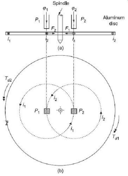
FIG. 1 Working principle of induction-type instrument: (a) Front view
(b) Top view Let f1 and f2 are the instantaneous values of two fluxes having
a phase difference of a between them. Therefore, we can write where, f1m
and f2m are peak values of fluxes f1 and f2 respectively.
The flux f1 will produce an alternating emf is the disc, given by Similarly, the alternating emf produced in the disc due to the flux f2 is given by If, is considered to the impedance of the aluminum disc with power factor ß then eddy current induced in the disc due to the emf e1 can be expressed as Similarly, eddy current induced in the disc due to the emf e2 is given by Instantaneous torque developed in proportional to the product of instantaneous current and instantaneous flux are those that interact with each other to produce the torque in question.
instantaneous torque Td1 produced due to interaction of the current i1 and flux f2 is given by
Similarly, instantaneous torque Td2 produced due to interaction of the current i2 and flux f1 is given by Total deflecting torque can thus be calculated as The following two observations can be made from Eq. (1):
1. The torque is directly proportional to the power factor of the aluminum disc (cos ß). Thus, to increase the deflecting torque, the path of eddy current in the disc must be as resistive as possible, so that value of cos ß is as high as possible.
2. The torque is directly proportional to sin a. Therefore, to have large deflecting torque, the angle a between the two fluxes should preferably be as nearly as possible close to 90°.
2.2 Constructional Details of Induction-Type Energy Meter
Constructional details of an induction-type single-phase energy meter are schematically shown in FIG. 2(a). The photograph of such an arrangement is shown in FIG. 2(b).
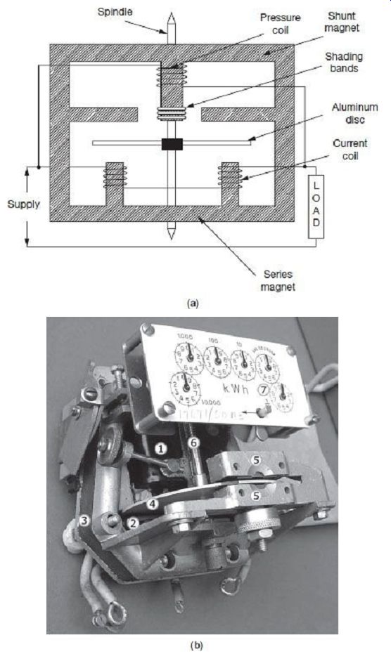
FIG. 2 (a) Constructional details of induction-type single-phase energy
meter (b) Photograph of induction-type single-phase energy meter (Creative
Commons Attribution Share Alike 2.5)
1. Voltage coil-many turns of fine wire encased in plastic, connected in parallel with load.
2. Current coil-few turns of thick wire, connected in series with load
3. Stator-concentrates and confines magnetic field.
4. Aluminum rotor disc.
5. Rotor brake magnets
6. Spindle with worm gear.
7. Display dials A single phase energy meter has four essential parts:
(i) Operating system (ii) Moving system (iii) Braking system (iv) Registering system
1. Operating System
The operating system consists of two electromagnets. The cores of these electromagnets are made of silicon steel laminations. The coils of one of these electromagnets (series magnet) are connected in series with the load, and is called the current coil. The other electromagnet (shunt magnet) is wound with a coil that is connected across the supply, called the pressure coil. The pressure coil, thus, carries a current that is proportional to supply voltage.
Shading bands made of copper are provided on the central limb of the shunt magnet.
Shading bands, as will be described later, are used to bring the flux i - Bearing produced by a shunt magnet exactly in quadrature Pivot with the applied voltage.
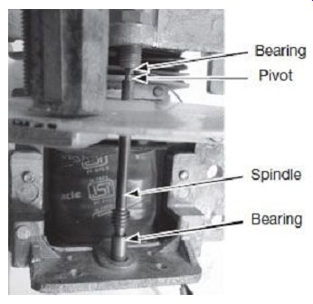
FIG. 3 Pivot and jewel bearing
2. Moving System
The moving system consists of a light aluminum disc mounted on a spindle. The disc is placed in the space between the series and shunt magnets. The disc is so positioned that it intersects the flux produced by both the magnets. The deflecting torque on the disc is produced by interaction between these fluxes and the eddy current they induce in the disc.
In energy meters, there is no control spring as such, so that there is continuous rotation of the disc.
The spindle is supported by a steel pivot supported by jewel bearings at the two ends, as shown in FIG. 3. A unique design for suspension of the rotating disc is used in 'floating-shaft' energy meters. In such a construction, the rotating shaft has one small piece of permanent magnet at each end. The upper magnet is attracted by a magnet placed in the upper bearing, whereas the lower magnet is attracted by another magnet placed in the lower bearing. The moving system thus floats without touching either of the bearing surfaces. In this way, friction while movement of the disc is drastically reduced.
3. Braking System
The braking system consists of a braking device which is usually a permanent magnet positioned near the edge of the aluminum disc. The arrangement is shown in FIG. 4.
The emf induced in the aluminum disc due to relative motion between the rotating disc and the fixed permanent magnet (brake magnet) induces eddy current in the disc. This eddy current, while interacting with the brake magnet flux, produces a retarding or braking torque. This braking torque is proportional to speed of the rotating disc. When the braking torque becomes equal to the operating torque, the disc rotates at a steady speed.
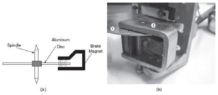
FIG. 4 Brake magnet to provide eddy current braking in induction-type
single-phase energy meter: (a) Schematic diagram (b) Actual picture (1) Aluminum
rotating disc (2) Brake magnet
The position of the permanent magnet with respect to the rotating disc is adjustable. Therefore, braking torque can be adjusted by shifting the permanent magnet to different radial positions with respect to the disc.
It is pertinent to mention here that the series magnet also acts as a braking magnet, since it opposes the main torque producing flux generated by the shunt magnet.
4. Registering System
The function of a registering or counting system is to continuously record a numerical value that is proportional to the number of revolutions made by the rotating system. By suitable combination of a train of reduction gears, rotation of the main aluminum disc can be transmitted to different pointers to register meter readings on different dials. Finally, the kWh reading can be obtained by multiplying the number of revolutions as pointed out by the dials with the meter constant. The photograph of such a dial-type registering system is shown in FIG. 5.
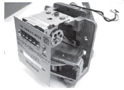
FIG. 5 Photograph of dial-type single phase energy meter
2.3 Operation of Induction-Type Energy Meter
As per construction, the pressure coil winding is made highly inductive by providing a large number of turns. The air gaps in a shunt magnet circuit are also made small to reduce the reluctance of shunt flux paths. Thus, as supply voltage is applied across the pressure coil, the current IP through the pressure coil is proportional to the supply voltage and lags behind it by an angle that is only a few degrees less than 90°. Ideally, this angle of lag should have been 90° but for the small unavoidable resistance present in the winding itself and the associated iron losses in the magnetic circuit.
FIG. 6 shows the path of different fluxes while the meter is under operation. The corresponding phasor diagram is shown in FIG. 7.
FIG. 6 Flux paths in induction-type single-phase energy meter FIG. 7 Phasor diagram of single-phase induction-type energy meter Let, V = supply voltage I = load current
? = phase angle of load
ß = phase angle of aluminum disc
a = phase angle between shunt magnet and series magnet fluxes
d = phase angle between supply voltage and pressure coil flux
The current IP produces a flux fpt that is in same phase as IP. This flux is made to divide itself in two parts, fg and fp. The major portion of total pressure coil flux, i.e., fg passes through the side gaps as shown in FIG. 6, as reluctance of these paths are low due very small air gaps. Remaining portion of the flux, i.e., fp passes through the disc and is responsible for production of the driving torque. Due to larger reluctance of the path, this flux fp is relatively weaker.
The flux fp is proportional to the current IP and is in the same phase, as shown in the phasor diagram of FIG. 7. The flux fp is thus proportional to the supply voltage V and lags it by an angle d which is only a few degrees less than 90°. The flux fp being alternating in nature, induces and eddy emf Eep in the disc, which in turn produces eddy current I. Depending on the impedance angle ß of the aluminum disc, eddy current I will lag behind the eddy emf Eep by an angle ß.
The load current I flows through the series magnet current coil and produces a flux fs.
This flux is proportional to the load current I and is in phase with it. This flux, in the same way, induces and eddy emf Ees in the disc, which in turn produces eddy current Ies. The eddy current Ies lags behind the eddy emf Ees by the same angle ß.
Now, the eddy current Ies interacts with flux fp to produce a torque and the eddy current Iep interacts with flux fs to produce another torque. These two torques are in opposite direction as shown in FIG. 1, and the resultant torque is the difference of these two.
Following (1), the resultant deflecting torque on the disc due to combined action of two fluxes fp and fs is given as where, Z is the impedance of the aluminum disc and ? is the angular frequency of supply voltage.
The driving torque can be re-written following the phasor diagram in FIG. 7 as Since we have, jp V and fs I, If N is the speed of rotation of the disc, then braking torque Tb = K4 N At steady running condition of the disc, the driving torque must equal the braking torque, If we can make d = 90° Thus, in order that the speed of rotation can be made to be proportionate to the power consumed, the angle difference d between the supply voltage V and the pressure coil flux fp must be made 90° Total number of revolutions within a time interval dt is If, e = 90°, total number of revolutions Thus, total number of revolutions is proportional to the energy consumed.
3. ERRORS IN INDUCTION-TYPE ENERGY METERS AND THEIR COMPENSATION
3.1 Phase-angle Error
It is clear from (7) that the meter will indicate true energy only if the phase angle between the pressure coil flux fp and the supply voltage V is 90°. This requires that the pressure coil winding should be designed as highly inductive and its resistance and iron losses should be made minimum. But, even then the phase angle is not exactly 90°, rather a few degrees less than 90°. Suitable adjustments can be implemented such that the shunt magnet flux linking with the disc can be made to lag the supply voltage by an angle exactly equal to 90°.
1. Shading Coil with Adjustable Resistance
FIG. 8 shows the arrangement where an additional coil (shading coil) with adjustable resistance is placed on the central limb of the shunt magnet close to the disc. Main flux created by the shunt magnet induces an emf in this shading coil. This emf creates its own flux. These two fluxes result in a modified flux to pass through the air gap to link the disc and thus produce the driving torque. With proper adjustment of the shading coil resistance, the resultant flux can be made to lag the supply voltage exactly by an angle of 90°.
Operation of the shading coil can be explained with the help of the phasor diagram shown in FIG. 9. The pressure coil, when excited from the supply voltage V, carries a current IP and produces an mmf ATpt which in turn produces the total flux fpt. The flux fpt lags the supply voltage V by an angle f which is slightly less than 90°. The current IP produces a flux fpt that is in same phase as IP. The flux fpt gets divided in two parts, f and fp. The portion of flux f passes through the side gaps as shown in FIG. 8, and remaining portion of the flux, i.e., fp passes through the disc and also the shading coil.
Due to linkage with the time varying flux, an emf Esc is induced in the shading coil that lags behind its originating flux fp by 90° (i.e. ESC is 180°) lagging behind the supply voltage V. This emf circulates and eddy current Isc through the shading coil itself. Isc lags behind the emf Esc by an angle ? that depends on the impedance of the shading coil. The shading coil current Isc produces an mmf ATsc which is in phase with Isc. The flux fp passing through to the disc will thus be due to the resultant mmf ATp which is summation of the original mmf ATpt and the mmf ATsc due to the shading coil. This flux fp will be in phase with the mmf ATp. As seen in the phasor diagram of FIG. 9, the flux fp can be made to lag the supply voltage V by exactly 90° if the mmf ATp or in other words, the shading coil phase angle ? can be adjusted properly. The shading coil phase angle can easily be adjusted by varying the external resistance connected to the shading coil.
FIG. 8 Shading coil for lag adjustment V FIG. 9 Phasor diagram showing operation of shading coil for lag adjustment
2. Copper Shading Bands
A similar result of lag adjustment can be obtained by the use of copper shading bands placed on the central limb of the shunt magnet. Such an arrangement is shown in FIG. 10. Following the same arguments, the resultant flux fp crossing over to the disc can be made to lag the supply voltage V by exactly 90° by proper adjustment of the mmf produced by the copper shading bands. Adjustments in this case can be done by moving the shading bands along the axis of the limb. As the bands are moved upwards along the limb, they embrace more flux. This results in increased values of induced emf, increased values of induced eddy current and hence increased values of the mmf produced by the bands. Similarly, as the bands are moved downwards, mmf produced by the bands is reduced. This changes the phase angle difference between fp and fpt , as can be observed from the phasor diagram of FIG. 9. Thus, careful adjustments of the copper shading bands position can make the phase difference between the supply voltage V and resultant shunt magnet flux fp to be exactly 90°.
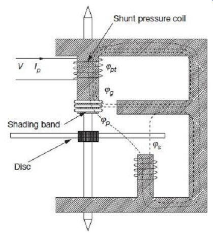
FIG. 10 Copper shading bands for lag adjustment
3.2 Error due to Friction at Light Loads
Friction in bearings can pose serious errors in measurement of energy in the form of that it will impede proper movement of the rotating disc. This problem is particularly objectionable at low loads, when the driving torque itself is very low; therefore, unwanted friction torque can even stop the disc from rotating. To avoid this, it is necessary to provide an additional torque that is essentially independent of the load, to be applied in the direction of the driving torque, i.e., opposite to the frictional torque to compensate for the frictional retarding torque. This is achieved by means of a small vane or shading loop placed in the air gap between the central limb of the shunt magnet and the aluminum disc, and slightly off-centre from the central limb, as shown in FIG. 11. Interactions between fluxes which are linked and not linked by the shading or compensating vane and the currents they induce in the disc result in a small driving torque that can compensate for the frictional retarding torque. The value of this small additional torque can be adjusted by lateral movement of the vane in and out of its position in the air gap.
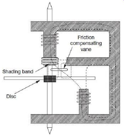
FIG. 11 Shading vane for friction compensation
3.3 Creeping Error
In some meters, a slow but continuous rotation of the disc can be observed even when there is no current flowing through the current coil, and only pressure coil is energized.
This is called creeping. The primary reason for creeping is due to over-compensation for friction. Though the main driving torque is absent at no-load, the additional torque provided by the friction compensating vane will make the disc continue to rotate. Other causes of creeping may be excessive voltage across the potential coil resulting in production of excessive torque by the friction compensating device, or vibrations, and stray magnetic fields.
Creeping can be avoided by drilling two holes on the aluminum disc placed on diametrically opposite locations. Drilling such holes will distort the eddy current paths along the disc and the disc will tend to stop with the holes coming underneath the shunt magnet poles. The disc can thus creep only till a maximum of half the rotation till one of the holes comes below the shunt magnet pole. This effect is however, too insignificant to hamper disc movement during normal running operations under load.
Creeping can also be avoided by attaching a tiny piece of iron to the edge of the disc.
The brake magnet in such a case can lock the iron piece to itself and prevent creeping of the disc. Once again, this action is too insignificant to hamper disc movement during normal running operations under load. The arrangement is schematically shown in FIG. 12.
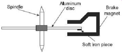
FIG. 12 Soft iron piece at the end of the disc to prevent creeping 8.3.4
Error due to Change in Temperature
Errors introduced by variation of temperature in induction-type energy meters are usually small since the various effects tend to neutralize each other. An increase in temperature increases the pressure coil resistance, thereby reducing pressure coil current and reducing pressure coil flux. This will tend to reduce the driving torque. But the flux of the brake magnet also reduces due to increase in temperature, thereby reducing the braking torque.
Again, an increase in temperature increases the resistance to eddy current path in the disc, which reduces both driving torque and braking torque. The various effects thus tend to neutralize each other.
The effects of increasing temperature, however, in general cause the meter to rotate faster and hence record higher values. Temperature effects thus need to be compensated for by using temperature shunts in the brake magnet.
3.5 Error due to Overload
At a constant voltage, the deflecting torque becomes simply proportional to the series magnet flux and hence proportional to the load current. This is due to the fact that from Eq. (2), at constant voltage as the shunt magnet flux fp is constant, the driving torque Td fs I.
On the other hand, as the disc rotates continuously in the field of the series magnet, an emf is induced dynamically in the disc due to its linkage with the series magnet flux fs.
This emf induces eddy currents in the disc that interact with the series magnet flux to create a retarding or braking torque that opposes motion of the disc. This self braking torque is proportional to the square of the series magnet flux or is proportional to the square of the load current; i.e., Tb f2 s I 2.
At higher loads, thus the braking torque overpowers the deflecting torque and the meter tends to rotate at slower speed, and consequently reads lower than actual.
To avoid such errors, and to minimize the self-braking action, the full load speed of the disc is set at lower values. The current coil flux fs is made smaller as compared to the pressure coil flux fp. Thus, the dynamically induced emf that causes the braking torque is restricted as compared to the driving torque. Magnetic shunts are also sometimes used with series magnets to compensate for overload errors at high current values.
3.6 Error due to Voltage Variations
Voltage variations can cause errors in induction-type energy meters mainly due to two reasons:
1. At too high voltages, the relationship between the supply voltage V and the shunt magnet flux fp no longer remain linear due to saturation of iron parts, and
2. For sudden fluctuations in supply voltage, the shunt magnet flux fp produces a dynamically induced emf in the disc which in turn results in a self-braking torque and the disc rotation is hampered.
Compensation for voltage variation is provided by using a suitable magnetic shunt that diverts a major portion of the flux through the disc when the voltage rises, thereby increasing the driving torque to overcome the self-braking torque. Such compensation can be achieved by increasing the reluctance of the side limbs of the shunt magnet. This is done by providing holes in the side limbs as shown in FIG. 13.
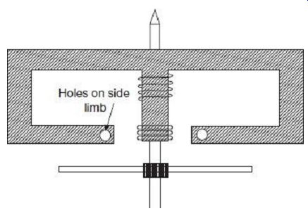
FIG. 13 Holes provided on side limbs to compensate for errors due to
sudden voltage variations
4. TESTING OF ENERGY METERS
Energy meters are tested at the following conditions:
1. At 5% of rated current at unity power factor
2. At 100% or 125% of rated current with unity power factor
3. At one intermediate load with unity power factor
4. At rated current and 0.5 lagging power factor
5. Creep test With pressure coil supplied with 110% of rated voltage and current coil open circuited, the meter disc should not rotate by more than one revolution, i.e., it should not creep
6. Starting test At 0.5% of rated current and full rated voltage, the meter disc should start rotating
4.1 Phantom Loading
When the current rating of the meter under test is high, a test with actual loading arrangements would involve considerable wastage of energy and also it is difficult to arrange for such large loads under laboratory test conditions. In such cases, to avoid this, 'phantom' or 'fictitious' loading arrangements are done for testing of energy meters.
Phantom loading consists of supplying the shunt magnet pressure coil circuit from a rated voltage source. The series magnet current coil is supplied from a separate low voltage supply source. It is possible to circulate rated current through the current coil circuit with the low voltage source since impedance of this circuit is very low. The energy indicated by the meter under phantom loading condition is the same as the energy indication as would have been with a real load. With this arrangement, the total energy consumed for the test is comparatively smaller. The total energy required for the test is that due to the small pressure coil current at rated voltage and small current coil voltage at rated current.
QUIZ
Objective Questions
1. Energy meters do not have a control spring to (a) avoid unnecessary friction losses (b) enable continuous rotation of the disc (c) avoid damping during movement (d) all of the above
2. In induction-type energy meters, the speed of rotation of the disc is proportional to the (a) energy consumption (b) power consumption (c) derivative of power consumption (d) none of the above
3. The advantages of induction-type energy meters are (a) low torque/weight ratio (b) low friction (c) high and sustained accuracy (d) all of the above
4. Induction-type energy meters have aluminum disc as the rotating part so that (a) flux can pass through the rotating part (b) eddy current can be induced in the rotating part (c) creeping error can be avoided (d) all of the above
5. In induction-type energy meters (a) pressure coil is the moving part (b) current coil is the moving part (c) both current and pressure coils are moving (d) both current and pressure coils are stationary
6. In induction-type energy meters, high driving torque can be obtained by (a) making the disc purely resistive (b) making the phase difference between the two operating fluxes as large as possible (c) making the disc impedance as low as possible (d) all of the above
7. Braking torque provided by the permanent magnet in an induction-type energy meter is proportional to (a) speed of the rotating disc (b) square of the flux of the permanent magnet (c) distance of the permanent magnet with respect to centre of the disc (d) all of the above
8. Braking torque provided by the permanent magnet in an induction-type energy meter can be changed by (a) providing a metal shunt and shifting its position (b) moving the position of the permanent magnet with respect to the disc (c) both (a) and (b) (d) none of the above
9. In single-phase induction-type energy meters, maximum torque is produced when the shunt magnet flux (a) leads the supply voltage by 90° (b) lags the supply voltage by 90° (c) lags the supply voltage by 45° (d) is in phase with the supply voltage
10. In single-phase induction-type energy meters, lag adjustments are done by (a) permanent magnet placed on the edge of the disc (b) holes provided on the side limbs of the pressure coil (c) copper shading bands placed on the central limb of the pressure coil (d) metal shunts placed on the series magnets
11. In single-phase induction-type energy meters, lag adjustments can be done by (a) shifting the copper shading band along the axis of the central limb (b) varying the external resistance connected to the shading coil placed on the central limb (c) either of (a) or (b) as the case may be (d) none of the above
12. In single-phase induction-type energy meters, friction compensation can be done by (a) placing shading bands in the gap between central limb and the disc (b) drilling diametrically opposite holes on the disc (c) providing holes on the side limbs (d) all of the above
13. Creeping in a single-phase energy meter may be due to (a) vibration (b) overcompensation of friction (c) over voltages (d) all of the above
14. Creeping in a single-phase energy meter can be avoided by (a) using good quality bearings (b) increasing strength of the brake magnet (c) placing small soft iron piece on edge of the rotating disc (d) all of the above
15. Increase in operating temperature in an induction-type energy meter will (a) reduce pressure coil flux (b) reduce braking torque (c) reduce driving torque (d) all of the above
16. Overload errors in induction-type energy meters can be reduced by (a) designing the meter to run at lower rated speeds (b) designing the current coil flux to have lower rated values as compared to pressure coil flux (c) providing magnetic shunts along with series magnets that saturate at higher loads (d) all of the above
17. Over voltages may hamper rotation of the disc in induction-type energy meters since (a) the pressure coil flux no longer remains in quadrature with the current coil flux (b) dynamically induced emf in the disc from the pressure coil flux produces a self-braking torque (c) effect of the brake magnet is enhanced (d) all of the above
18. If an induction-type energy meter runs fast, it can be slowed down by (a) moving up the copper shading bands placed on the central limb (b) adjusting the magnetic shunt placed on the series magnets (c) moving the permanent brake magnet away from centre of the disc (d) bringing the permanent brake magnet closer to centre of the disc
19. Phantom loading for testing of energy meters is used (a) for meters having low current ratings (b) to isolate current and potential circuits (c) to test meters having a large current rating for which loads may not be available in the laboratory (d) all of the above
20. In single-phase induction-type energy meters, direction of rotation of the disc can be reversed by (a) reversing supply terminals (b) reversing load terminals (c) opening the meter and reversing either the potential coil terminals or the current coil terminals (d) opening the meter and reversing both the potential coil terminals and the current coil terminals
Questions
1. Draw a schematic diagram showing construction details of an induction-type energy meter and label its different parts. Comment on the different materials used for the different internal components.
2. Why braking torque is necessary in induction type energy meters? Draw and explain how braking arrangement is done such instruments.
3. Why is it necessary to have lag adjustment devices in induction type energy meters? Draw and explain in brief, operation of such arrangements in a single-phase energy meter.
4. What is the effect of friction in induction-type energy meters? How is it overcome in practice? 5. What is creeping error in an energy meter? What are its possible causes? How can it be compensated in an induction type energy meter? 6. Explain the effects of over-load in induction type energy meters. How can this effect be avoided? 7. Why can sudden voltage variations cause errors in induction type energy meter readings? Discuss how these errors can be minimized.
8. List the tests normally carried out on single phase energy meters? Why phantom loading arrangement is done for testing high capacity energy meters? More Questions 1. Derive an expression for the driving torque in a single phase induction type meter. Show that the driving torque is maximum when the phase angle between the two fluxes is 900 and the rotating disc is purely non-inductive.
2. Draw the schematic diagram of the internal operating parts of a single phase induction type energy meter.
Comment of the materials used and operation of the different internal parts.
3. Draw and describe the relevant phasor diagram and derive how the number of revolutions in a single phase induction type energy meter is proportional to the energy consumed.
4. (a) Explain the sources of error in a single phase induction type energy meter.
(b) A 220 V, 5 A energy meter on full load unity power factor test makes 60 revolutions in 360 seconds. If the designed speed of the disc is 550 revolutions per kWh, find the percentage error.
5. (a) What is phase angle error in an induction type energy meter? Explain how this error is reduced in a single phase induction type energy meter.
(b) An energy meter is designed to have 60 revolutions of the disc per unit of energy consumed. Calculate the number of revolutions made by the disc when measuring the energy consumed by a load carrying 20 A at 230 V and 0.4 power factor. Find the percentage error if the meter actually makes 110 revolutions.
6. (a) What is the effect of friction in induction-type energy meters? How is it overcome? What is creeping error? How is it overcome? (b) A 230 V single-phase watthour meter records a constant load of 5 A for 6 hours at unity power factor. If the meter disc makes 2760 revolutions during this period, what is the meter constant in terms of revolutions per unit? Calculate the load power factor if the number of revolutions made by the meter is 1712 when recording 4 A at 230 V for 5 hours.
7. (a) What are the tests normally carried out on single-phase energy meters? Why is phantom loading arrangement is done for testing high capacity energy meters? (b) A 230 V, 5 A dc energy meter is tested for its name plate ratings. Resistance of the pressure coil circuit is 6000 O and that of current coil itself is 0.15 O. Calculate the energy consumed when testing for a period of 2 hours with
(i) Direct loading arrangement
(ii) Phantom loading with the current coil circuit excited by a separate 6 V battery