AMAZON multi-meters discounts AMAZON oscilloscope discounts
1. How to Destroy a Vacuum System
Carpenters have a saying "measure twice, cut once." This saying implies that any extra time spent in preparation saves time and materials that may otherwise be wasted. Likewise, any time spent preparing an experiment or equipment (including general maintenance) saves time and materials and, potentially, may also save a life.
This section lists fundamental potential pitfalls when working with a vacuum system. If you read no other section in this guide, read this one. By following the rules and guidelines that you are directed to within this section, many hours, and perhaps weeks, of problems will be avoided. It is better to avoid the situation of "not having enough time to do it right, but plenty of time to repair the wrong." This list is not meant to be comprehensive-it cannot be. It is, however, a collection of the more common disasters that occur on a laboratory vacuum system.
1. Blowing up a vacuum line by freezing air in a trap (see Section 4.3)
2. Sudden bursts of pressure in McLeod gauges that can cause mercury to spray throughout a line (problem) or break a line (big problem) (see Secs. 5.6-5.9)
3. Breaking stopcocks off vacuum lines (see Section 7.1, point 8)
4. Breaking off glass hose connections when pulling flexible tubing off (see Section 3.17)
5. Destroying the oil in a diffusion pump (see Section 3.1)
6. Destroying the oil in a mechanical pump (see Section 4.1)
7. Destroying a mechanical pump (see Section 3.4)
8. Wasting time re-evacuating vacuum lines (see Section 3.14)
9. Causing virtual leaks in cold traps (see Section 4.3)
10. Frothing the oil of a two-stage pump (see Section 3.3)
11. Breaking a cold trap off a vacuum line by not venting it to the atmosphere before removing the bottom (see Section 4.4)
12. Achieving a poor-quality vacuum when starting a vacuum system up for the first time (see Section 6.3)
13. Dissolving O-rings during vacuum leak detection (see Section 6.6).
14. Punching holes in glass with a Tesla coil (see Section 6.7)
15. Burning the filament of an ion gauge (see Section 5.20)
16. Imploding glass items on a vacuum system (see Section 7.1, point 2)
17. Placing items on a vacuum rack so that they fall into the rack (see Section 7.1, point 3)
18. Breaking vacuum system tubing when tightening two and/or three finger clamps on a vacuum rack (see Section 7.1, point 4)
19. Sucking mechanical pump oil into a vacuum line (see Section 3.4)
2. An Overview of Vacuum Science and Technology
2.1 Preface
In this guide I have intentionally avoided equations whenever possible. The reason is simple: Most people do not need, or use, equations when using equipment. Despite that, this introductory section on vacuum technology contains equations.
They are presented so the reader may better understand the relationship between the various forces in vacuum systems. None are derived, and none are used beyond presenting some basic points. If you are interested in the derivation of any formula, see the recommended books at the end of this section.
It is not necessary to know the material in this introductory section to run a vacuum system. However, it does explain terms and ideas that are used throughout the rest of this section. Because of the basic information contained within, I recommend that you read this section.
Vacuum systems are used in the lab for such purposes as: preventing unwanted reactions (with oxygen and/or other reactive gases); distilling or fractionally distilling compounds (a vacuum can lower the boiling point of a compound); or transferring materials from one part of a system to another (using cryogenic transfer). A vacuum system can also be used for more sophisticated processes such as thin film deposition, electron microscopy, and enough other processes that just to list them could fill a book.
The goal in creating a vacuum is to get rid of, or bind up, a significant amount of the gases and vapors (mostly air and water vapor) within a vacuum system. Regardless of the approach, the goal is a net reduction of pressure in the system.
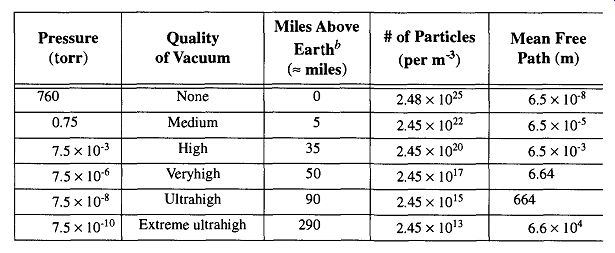
A perfect vacuum is a lack of everything, and we must accept that we cannot achieve this state in the laboratory. Table 1 illustrates that by decreasing a vacuum to 10^-3 torr (a good-quality vacuum in a standard lab) we can remove over 99.99% of the particles* that are present at room pressure. At 10^-6 torr, a high vacuum, there is still quite a considerable number of particles remaining (2.45 x 10^17 / m3 ). Despite the (seemingly) large quantity of particles remaining, this vacuum is still sufficient to successfully limit the chance of oxidation and/or unwanted reactions for many laboratory requirements. More than 95% of all vacuum studies and technique can be successfully achieved within the vacuum ranges of 10^- 2 to 10^-6 torr. The other 5% (studies in the ultrahigh-vacuum range) consist of surface and material studies and space simulation, which require as little contamination as possible.
Table
1 Pressure, Particles, and the Mean Free Path. -- This table is based on
dry air because of the daily variations of water vapor. -- These approximate
values are provided to allow the reader to appreciate the value, and difficulties,
of space travel.
[For this discussion, water vapor has been ignored because its percent concentration varies on a day to-day basis.]
Aside from earthbound technological approaches to achieve a vacuum, the further away from the earth's surface you go, the less atmosphere there is and there fore the greater the vacuum (relative to atmospheric pressure on the earth's surface) that can be achieved. In fact, on earth, someone standing on top of Mt. McKinley experiences vacuum greater than can be created with a standard vacuum cleaner at sea level. Table 1 shows the approximate miles above earth to obtain various conditions of vacuum. As this table shows, outer space offers wonderful opportunities to produce vacuum conditions for experimental or industrial work. Outer space can provide an infinite vacuum system, an essentially contamination-free environment, and blip free (no pressure surge) conditions. The possibilities of ultra-vacuum research in space is discussed by Naumann in his paper on the SURF (Space Ultravacuum Research Facility) system.
Unfortunately, space is an opportunity that is as far from the expected uses of this guide (no pun intended) as one can get. Back on earth we are still limited to using pumps, traps, oils, gauges, glass, metal-support clamps, elastomers, and other implements of laboratory vacuum systems.
Although vacuum systems are not as expensive as space travel, they are not inexpensive, and the greater the vacuum desired, the more expensive it will be to achieve. If anyone is concerned about the bottom line, it is important to consider your needs before you begin designing your system. Not only is there an increase in the cost of pumping equipment to cover the range from poor- to good-quality vacuums (mechanical to diffusion to turbomolecular to cryogenic pumps), but there are also the correspondingly increasing costs of support equipment (power supplies, thermocouple and ion gauges, and their controllers), peripheral equipment (mass spectrometry and/or He leak detectors), peripheral supplies (cooling water, Dewars, and liquid nitrogen), and support staff (technicians to run and/or maintain the equipment). These requirements can all add up.
Sometimes, you will have no alternative but to use comparatively expensive equipment. For example, a diffusion pump must be used in conjunction with a reasonably powerful (and therefore relatively more expensive) mechanical pump: If you were to use the diffusion pump with a small classroom demonstration mechanical pump, the diffusion pump would not work. On the other hand, do not assume that price is necessarily indicative of the best choice in equipment. You need to match components by their capabilities. That is, if your system is capable of only a low vacuum, you are wasting money purchasing a gauge designed with high-vacuum capabilities (which can be significantly more expensive). The requirement of matching components is equally important whether you are purchasing vacuum equipment from scratch or adding to components you already own.
Because a perfect vacuum cannot be achieved, and the next best thing (outer space) is for all intents and purposes out of reach, there are definable limits to the ultimate pressure of any system you are planning. These limits are based on:
1. How much you can spend
2. How much maintenance you are willing/needing to do
3. What supplies and materials you have (or can have) available
4. Your vacuum experience and knowledge
5. What technical support you have available
It is therefore important that you know what the demands and needs of your experimental work are. It is neither economical nor practical to have an elaborate vacuum system for simple vacuum needs.
2.2 How to Use a Vacuum System
The easiest way to explain a vacuum system is to explain each part of the vacuum system individually. However, the only way to use a vacuum system is to use all parts. Therefore, there is a conflict of interest in coordinating a section that will explain the parts of vacuum systems in general and how to use your vacuum system in specific.
If you are starting to use a vacuum system for the first time, Simply skim this entire section. Afterward, study your vacuum system and see what components you recognize from what you've read. Finally, re-read the sections of this section that are pertinent to your system. This method of study may seem like a lot of work before you turn on a switch or twist a stopcock, but the vacuum system you save may be your own.
Due to variations in equipment, controllers, and designs, what you see on your system will probably not be what you see in this guide. You will have to accommodate and respond accordingly. In addition, re-read Section 1 and be sure you under stand how accidents (disasters) can happen and how they can be avoided. That knowledge in itself will be the first major step to successful vacuum practice.
2.3 The History of Vacuum Equipment
It is interesting, when looking back on history, to see how much has happened, and yet how little things have really changed. The following information is by no means comprehensive. At best, it is meant to provide the reader with an appreciation of how long ago some vacuum equipment was invented. For example, the McLeod gauge and Toepler pump were invented over a hundred years ago. Over the years, there have been many improvements made in such items as the ion gauge and diffusion pump; however, the principles on which they work are so fundamental that their importance and use have not been lost. Currently, advances in solid state electronics are providing new technology and methods for a variety of equipment, but they all are variations and/or adoptions of what we already have. Simply put, history shows us that there have been a variety of attempts to remove something from someplace and correspondingly, try and figure out how much has been removed.
Aristotle, some 1650 years ago, was one of the first to make any serious comments about vacuum that have survived time. Aristotle could not accept the concept of a void, which led to his statement, "nature abhors a vacuum." This comment may not tell us very much about what is taking place in a vacuum, but it is as true now as it was then.
The first vacuum science work is credited to Evangelista Torricelli. In 1641, Torricelli was invited to Florence to serve as Galileo's secretary (during his last 3 months of life) as Galileo was still in his forced imprisonment and was blind.
After Galileo's death, he was appointed court philosopher and mathematician to Grand Duke Ferdinando II of Tuscany. This title let him do research without having any teaching responsibilities at the university. It is not fully clear as to whether he was following up on a previous suggestion from Galileo or continuing some work of another Italian, Gasparo Berti,* but in 1644 he filled a glass tube (four feet long) with mercury and inverted it with the opened end pouring into a small basing As expected, some of the mercury did pour out, but most stayed in the tube, leaving an empty portion in the closed end of the tube. By doing this, Torricelli is credited for creating the first sustained vacuum. It was believed, at the time, that what had been created was a perfect vacuum. Fortunately, Torricelli was a good observer and noticed that the height of the mercury actually changed day to day, thus "discovering" the barometer. Oddly enough, Torricelli never formally published his observations.
[In 1640, Berti had created a water barometer with a series of valves to eliminate the need of turning the apparatus upside down. He placed a bell in an enlargement of the glass tube near the top (evacuated) section. Berti correctly deduced that a vacuum would prevent observers from hearing the bell. Unfortunately, the rods connecting the bell to the glass chamber at the top of the device conducted the sound, making any evidence of vacuum impossible to detect. Because of poor design setup, an excellent scientific concept was lost and miscredited.
- The actual work may have been done by his colleague, Vincenzo Vivian.
* The difference between the two-a force pushing rather than a void pulling-is fundamental to understanding the movement of materials in a vacuum. Pressure is a force, and a vacuum is not an opposite (nor equal) force. A vacuum is simply a region with less pressure when compared to a region with greater pressure, and it is the molecules creating that pressure by pushing that creates a force rather than a lack of molecules creating a negative pressure by pulling.]
Torricelli's work was taken up by Pascal, a French mathematician and philosopher, He repeated Torricelli's work, but he used glass tubes 46 feet long and wine. His work also demonstrated that the atmosphere could only support 33 feet of wine (whose specific gravity is similar to water). Pascal's brother-in-law, Perier, joined the experimentation by taking a mercury "barometer" up the mountain Puy de Dome (= 1000m) and observed that the height of the column was 7.5 mm shorter than it was at the base of the mountain. This ingenious experiment helped to demonstrated that the force at work was the atmosphere pushing rather than a vacuum pulling, and that there was a vacuum at the top of the column.*
The next major technological breakthrough came from Otto von Guericke, a German burgomaster who invented a piston vacuum pump (which he called an air pump) that was capable of producing the best vacuum of the time. At first, Guericke pumped the water out of a barrel of water and observers were able to hear air leaking into the barrel refilling the void. Later he pumped out a copper sphere which immediately was loudly crushed (by air pressure). He then (wisely) had a better sphere created out of bronze, but did it in two halves. With these two hemi spheres, Guericke became sort of a vacuum showman and is most known for these Magdeburg hemispheres. The two hollow bronze hemispheres were sealed by evacuating the space between the halves. Two teams of horses, each attached to a respective half, could not pull them apart. However, by opening the evacuated space to the atmosphere and allowing air into the sphere, the hemispheres fell apart on their own.* It was Guericke who correctly theorized that it was differences in air pressure that cause the winds.
Robert Boyle (a founder of the Royal Society of England) heard about Guericke's pump and experiments and decided to scientifically analyze them. Aside from making improvements upon the design of the air pump, he also developed the relationship between gas pressure, volume, and temperature. This relationship was later called Boyle's law [see Eq. (2)].
The 17th century saw the beginning studies of electric discharges within a vacuum by Nollet in Paris in the 1740s. These studies were later refined by Faraday in England during the late 1830s and by Crookes in the late 1870s.
Manometers were eventually used as measurement devices. By the 1770s, mercury was boiled to increase measurement accuracy. Thus, albeit crudely, both out gassing and baking out of a vacuum system were instigated.
In 1851, Newman developed a mechanical pump that achieved a vacuum of 30.06 in. of mercury on a day that the barometer was reading 30.08 in. This pump was very impressive for the time. Vacuum technology was further enhanced by the invention of the Toepler pump in 1862, the Sprengel pump in 1865, and the McLeod gauge in 1874.
The "Dewar", invented by Dewar in the early 1890s, utilized the combined effect's of evacuating and silvering the empty space of a double wall container. Later, having the ability to keep things cold, Dewar developed the basic concepts of cryopumps by superchilling charcoal for absorbing gases.
In the 1910s, Gaede invented the mercury diffusion pump that was later improved by Langmuir (from the General Electric Co.), and improved yet again by Crawford, and yet again by Buckley. In the 1920s, industry began substituting refined oil for mercury in diffusion pumps.
The new century saw an abundant development of vacuum gauges. Both types of thermal conductivity gauges were invented in 1906 (Pirani inventing the Pirani gauge and Voege inventing the thermocouple gauge). The hot cathode gauge was invented by Von Baeyer in 1909 and the cold cathode gauge was invented by Penning in 1937. The early 1950s saw improvements in both the hot cathode gauge (by Bayard and Alpert) and cold cathode gauge (by Beck and Brisbane). Redhead made improvements on both types of gauges a few years later.
Since 1945, the fields of vacuum physics, technology, and technique have become the backbone of modern industrial production. From energy development and refinement, to silicon chips in watches, games, and computers, all are dependent on "striving for nothing."
[An interesting (and useful) way to duplicate this experiment is with an evacuated screw-top jar that you are unable to open. Take a knife, screwdriver, can opener (church key), or any prying device with which you can pry the lid away from the glass enough to momentarily distort the shape and allow air into the container. You will hear a momentary "pssst" as air enters, as well as a click of the metal as its shape goes from concave to normal. It will now be very simple to open the jar.]
2.4 Pressure, Vacuum, and Force
Gas pressure can be loosely imagined as the pounding of atoms and molecules (a force) against a wall (a defined area). As molecular activity increases (for instance by heating), the atoms and molecules pound away with greater activity, resulting in an increase in pressure. In addition, if some gas molecules are removed, there is more room for the remaining ones to move around, and fewer are available to hit the wall. This activity results in a drop in pressure. We use atmospheric pressure (which varies itself) as a dividing line for describing what is a vacuum or pressure environment: That environment which is greater than atmospheric pressure is a pressure, whereas that environment which is lower than atmospheric pressure is a vacuum. However, a positive pressure can only be defined by comparing it with something else that has less pressure, even if both are vacuums when compared to atmospheric pressure.
Units of pressure and vacuum should be identified as force per unit of area, and pressure units typically are mbar, psi, and kg/cm^2. Pressures below 1 torr (=10^- 3 atm) for many years were described in relationship to standard atmosphere* in various ways such as:
1. Millimeters of mercury (1/760 of a standard atmosphere)
2. Torr (= 1/760 of a standard atmosphere)
3. Micron (u) of mercury (1/1000 of a millimeter of mercury and/or 1/1000 of a torr)
4. Millitorr (also 1/1000 of a millimeter of mercury and/or 1/1000 of a torr) Whether one uses millimeters, torr, microns, or millitorr, a unit of force is being determined by a unit of length. To maintain the relationship of force per unit of area used in pressure and vacuum, the SI* decided on the term Pascal (one Newton per square meter) as a unit of vacuum. ** Regrettably, the acceptance of the Pascal has been as successful as metrics in the United States. The numeric relationship between all of these designation can be seen in Table 2.
Vacuum and pressure measurements were all originally made compared to atmospheric pressure, or "gauge" pressure. The term psig (pounds per square inch-gauge) refers to this comparison. Absolute pressure includes atmospheric pressure (14.7 psi) and is called psia (pounds per square inch-absolute). For example, your tire pressure is 35 psig or 49.7 psia. Generally, unless otherwise identified, the lone identification psi refers to gauge pressure.
[ * Standard atmosphere is the average pressure that the atmosphere exerts at 0°C, sea level.
- One torr is equal to 1 mm of mercury.
* International System of Units, see section 2.
** It is ironic that the first term torr, from Torricelli, and the later term Pascal, from the mathematician by the same name, were both selected as terms for vacuum units since neither man was really fundamental in vacuum history. Important yes, but not fundamental. ]
2.5 Gases, Vapors, and the Gas Laws
A vapor is a gas that is near its condensation temperature and/or pressure. At room temperature and pressure, gaseous water is a vapor; in a steel furnace, gaseous water is a gas. Some gases (hydrogen, helium, nitrogen, oxygen, and other cryogenic gases) do not have a vapor state anywhere near STP and are sometimes called permanent gases. For more information on condensation as well as evaporation and equilibrium, see Section 2.6.
Of the three states of matter (solid, liquid, and gas), only gases have radically changing distances between molecules. When the distances between the molecules of a gas are different than what is found at STP (Standard Temperature and Pressure), we have either a positive or negative pressure (compared to atmospheric).
As far as a gas is concerned, it does not make a difference whether the size of the container, the temperature of the gas, or the amount of gas has changed. All these conditions separately or together can change the pressure within a container.
Analysis of contained gases led to the following gas laws, most of which go by the name of the researcher who formally identified them:
1. All gases uniformly fill all spaces within a container. This space is called the volume (V). There cannot be an independent localized collection of gases exerting uneven pressures within a container.
2. All gases exert an equal pressure on all points of a container. Regardless of the shape of the container (on a static system), there can be no variation of gas pressure from any one point to any other point within that container.
3. All gases exhibit a direct relationship between the temperature and pres sure for a given volume and given amount of gas. Assuming that nothing else changes, if the temperature increases, the pressure will increase a directly proportional amount.
Charles' Law P
( 1)
4. All gases exhibit an inverse relationship between the volume and the pressure of a gas for a given temperature and amount of gas. Assuming that nothing else changes, if the volume increases, the pressure will decrease a directly proportional amount.
Boyle's Law PV = (constant) = P1V1 = P2V2 ( 2)
5. All gases of equal volumes, at the same temperature and pressure, contain the same number of molecules. The size of a gas atom (or molecule) has no relationship to pressure, temperature, or volume.
Avogadro's Law

( 3)
6. All gases exhibit a uniform relationship between the pressure and volume, temperature, and number of molecules present. This relationship is represented by the gas constant R (which is = 62.4 torrliter/molK) when Pressure is in torr, Volume is in liters, Temperature is in K, and n is the number of moles.
Ideal Gas Law
Pv = nRT ( 4)
7. If more than one gas is in a container, and the gases are not interacting, each gas will exhibit its own characteristic pressure. The sum of these individual pressures equals the total pressure. The percentage of each partial pressure is equal to the percentage of that gas in the sample.
Dalton's Law of Partial Pressures
Pt = P1 +P 2 + P3 + ... ( 5)
[ A mole is an Avogadro's number (6.023 x 10^23 ) of molecules. One mole is equal to one atomic mass, or the molar mass of a molecule or atom. For example, one mole of carbon (atomic mass 12) is equal to 12.01115 g.]
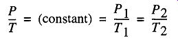
Laws 3, 4, and 5 are pulled together to create the ideal gas law, and the effects of it are shown pictorially in Fig. 1, where three different approaches to doubling the pressure are demonstrated. In Box A we have a given number of molecules at a given temperature and pressure in a container of one unit. In Box B, we have doubled the temperature, which causes the molecules to double their activity, which doubles the pressure. For Box C we have brought the temperature back to the original temperature, but have doubled the number of molecules within the container, which causes a doubling of the pressure. Finally, in Box D we have the same original temperature and the same number of molecules as in Box A, but we have decreased the size of the box by half, which doubles the pressure.
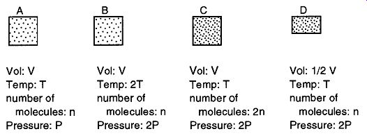
Fig. 1 Notice how you can double the pressure of a container by either
doubling the temperature, doubling the number of molecules, or halving the
volume.
Remember that these are ideal gas laws, and in nature, gases do not necessarily behave ideally. This is typically because some other force is preventing the ideal gas law from performing ideally. For example, the first gas law states that all gases uniformly fill a container. Yet, in Section 2.8, Barbour demonstrates that if a system does not have effective conductance, it is possible for a system to maintain unequal pressures in different sections for a considerable period of time. The first gas law is still in force, but it is prevented from performing ideally due to another physical limitation: conductance. Additionally, anyone who has forced gases into a compressed gas tank or hastily removed them would have reason to doubt the ideal gas law graphically pointed out in Fig. 1, Box C. When gases are rapidly compressed in a confined area, there is typically a heat rise. Conversely, when gases are rapidly removed from a confined area, there is a typically a heat loss.
The ideal gas law very clearly states that if the volume is the same and you double the number of molecules, there will be a doubling of pressure. It says nothing about a change in temperature. The problem here is that independently of the ideal gas law, adiabatic compression (and expansion) is having a secondary effect on the system. The trick is, one must allow a sufficiently slow introduction or removal of gases from a confined space for the ideal gas law to predominate. The slow addition or removal of gas allows a sufficient amount of time for heat conductance through the gas, and no heat rise or loss is created.
Fig. 2 Evaporation, equilibrium, and condensation are dynamic processes of vapor pressure.
2.6 Vapor Pressure
The greatest vacuum that can be obtained within a system is solely dependent on the material with the greatest vapor pressure within the system. Remember, a vapor is a gas that is near its condensation temperature and/or pressure. As can be seen in Fig. 2, the evaporation, equilibrium, and condensation processes are dynamic conditions. That is, the molecules involved are not actually static after they have evaporated or condensed. For example, in evaporation, statistically more molecules are turning into a gas than are turning into a liquid (or solid); in condensation, statistically more molecules are turning into a liquid (or solid) than are turning into a gas; and, in equilibrium, the exchange is equal. Once equilibrium is achieved, the region is considered saturated.
The vapor pressure of a material creates the maximum vacuum potential that can be achieved against its evaporation rate at a given temperature. As a material evaporates, its molecules are included among those in the air envelope around the material. Normally, to obtain a vacuum, you are trying to rid (or bind up) the gas molecules within a vacuum. As long as the molecules you are trying to get rid of are being replaced, you cannot improve the quality of the vacuum. If water is in your system, your best vacuum is =18 torr. Not until the water finally evaporates off, or is frozen in a trap, can the system achieve a greater vacuum.
[The converse of this is heating. By heating water to its boiling point, its vapor pressure is the same as atmospheric pressure. Because atmospheric pressure varies as altitude (and weather conditions) varies, the boiling temperature varies. On the other hand, the temperature of gently boiling water is the same temperature as furiously boiling water.]
The vapor pressure of any given compound is dependent on its temperature and the pressure of its environment. As temperature is lowered, the vapor pressure of any compound also lowers.* Therefore, the easiest way to improve a vacuum is to lower the vapor pressure of the materials within the system by chilling with either water, dry ice, or liquid nitrogen. The choice of any of these coolants is typically dependent upon cost or availability. If you are limited in coolant choice, you can consider changing the materials you are working with to complement the range of coolants. For example, the vapor pressure of water is 4.6 torr at 0° C, 5 x 10^-4 at dry ice temperatures and ~10^-24 at liquid nitrogen temperatures. Thus, there may be little reason to use liquid nitrogen if you only want to achieve 10^-2 torr. That is not to say you can't or shouldn't, just that you don't need to use liquid nitrogen for that level of vacuum if water is your primary vapor contaminant.
Table 3 Composition of Dry Air---The partial pressure of water vapor in air
depends on temperature and relative humidity. For example, at 20°C (saturation
vapor pressure of water = 17.5 torr) and a relative humidity of 45%, the
partial pressure of water vapor would be 0.45 times 17.5 torr, or 8 torr.
Data taken from ref 9.
2.7 How to Make (and Maintain) a Vacuum
Aristotle's statement "nature abhors a vacuum" means that even if you are successful in creating a vacuum, your ability to maintain that vacuum can require an equal, if not greater, amount of work. When creating a vacuum, you must establish your needs, define (and understand) your conditions, consult with authorities before you make purchases, and understand (and accept) any compromises.
We often euphemistically refer to creating a vacuum as emptying a container of its contents. But, what does "empty" mean? We already stated that it is impossible to make a container void of contents, so what do we need to do to "empty" a container? There are three levels that should be considered when "emptying" a container.
For example, consider emptying a glass of water: First you take the glass and pour out the water. From a simple aspect, the glass is empty. However, there is still a film of water in the glass, so you dry the walls of the glass with a towel until they are dry to the touch. However, if you want the glass really dry, you need to bake out the water that has adsorbed on the walls and is absorbed into the glass walls (water can soak into a glass matrix up to 50 molecules deep). Thus, when we talk about creating a vacuum, until you remove the adsorbed (surface concentration) and absorbed (material penetration) gases and vapors, you do not have an "empty" system.
So, say that you take a glass, pour out the contents, dry the walls, and bake out the glass so it is truly empty. The question is, Will it now remain empty until water is poured back in? As far as vacuum science is concerned, no. As soon as the glass is exposed to the atmosphere at room temperature, the walls will re-saturate with water vapor, and the glass will no longer be empty. To maintain a glass as "empty," it must be isolated from the atmosphere. Otherwise you must repeat the drying process.
Unfortunately, glass vacuum systems cannot be "baked out" (as is done with metal vacuum systems) to remove adsorbed water. Baking is likely to damage stopcocks or rotary valves; or if the baking temperature is sufficiently high, the glass walls of the system itself. Thus, glass vacuum systems are not practical if baking your system is required.
What typically happens with a glass vacuum system is that first a mechanical pump removes a great deal of the "loose," or "free," gas particles. Then, greater vacuum is achieved with the combination of a diffusion pump (or similarly fast pumping unit) and traps that remove or bind up the various vapors within the sys tem (for example, oil, mercury, and water). The only way a system can achieve a vacuum lower than 10^-6 to 10^-7 torr is if the pump can remove water vapor faster than the water vapor can leave the walls. Most diffusion pumping systems cannot achieve this goal, but even if they could, there is such a substantial amount of water vapor within the glass that, unless the walls are baked, a better vacuum can not be obtained.
Aside from adsorbed gases, there are potential leaks in any vacuum system that must be dealt with or a viable vacuum cannot be created. Leaks and leak detection are dealt with in Section 6.
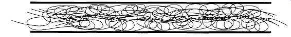
Fig. 3 Turbulent flow is primarily a gas-gas interactions.
2.8 Gas Flow
As one is trying to remove the various gases from a vacuum system, whether the system is a bell jar or a complex collection of tubing with valves or stopcocks all interconnected, the gases must pass through tubing of various types and sizes between the system, the pumps, and the outside world. Depending on the size of the connecting tubing, the length of the tubing, and the vacuum at any time, there can be significant performance changes throughout the system. This all has to do with how gases flow through tubing of different sizes and at different pressures.
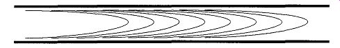
Fig. 4 Viscous gas flow.
There are three basic types of gas flow: turbulent, viscous, and molecular. The type of flow passing through a given system is dependent on both the mean free path (MFP) of the molecule(s) and the diameter of the container (tube) through which they are flowing. A useful formula when talking about MFP is the Knudsen number (Kn), defined in Eq. (6).
Kn = L/d - ( 6)
where L is the MFP
and d is the diameter of the tube in question
When a system is first brought into vacuum conditions from atmospheric pres sure, the flow is turbulent (see Fig. 3) and is not unlike the chaos seen in white water rapids. At this time, the MFP is approximately 9 x 10^-7 cm, which is considerably smaller than any tube the gas is likely to pass through. The great preponderance of interactions (that is, when a gas atom or molecule interacts with something else) are gas-gas, which means there is a greater likelihood that a molecule of gas will hit another molecule of gas than it will hit a wall.
As the pressure decreases, the next type of flow transition is called viscous flow. The nature of this flow is complex and is dependent on flow velocity, mass density, and the viscosity of the gas. Viscous flow is similar to the flow of water running down a slow, calm stream--the flow is fastest through the center of the tube, while the sides show a slow flow and there is zero flow rate at the walls (see Fig. 4). The gas interactions in viscous flow are gas-gas and gas-wall; in other words, a molecule is equally likely to hit a wall than another molecule.
When Kn of the system is <0.01, the flow is probably viscous. The transition between viscous and molecular flow is fairly straightforward: When 1 > Kn > 0.01, the flow is in transition to molecular flow; when 1 < Kn, there is a molecular flow.
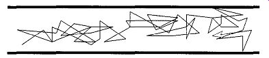
Fig. 5 When the mean free path is fairly short (relative to the inside
diameter of its container), a gas molecule to more likely hit another gas
molecule than the walls of the container. This situation is known as a gas-gas
interaction.
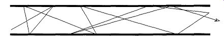
Fig. 6 When the mean free path is longer than the diameter of the container
of the gas, gas-wall interactions will predominate and you will have molecular
flow.
Typically, the first phase of molecular flow is gas-gas. That is, a molecule or atom is more likely to interact with another molecule or atom than the wall (see Fig. 5). As the pressure continues to drop and the mean free path increases, gas wall interactions become the predominant type of gas flow.
One of the more interesting characteristics of gas-wall interactions is that not only are the gas reflections not specular (mirror-like), but the molecule or atom may go back into the direction that it once came from (see Fig. 6). This bounce back is partly because, at the molecular level, wall surfaces are not smooth but very irregular. In addition, there is likely to be a time delay from the time a molecule hits a wall to the time it leaves the same wall. At the molecular level, when a molecule hits a wall surface, instead of reflection (like a billiard ball), the process is more likely to be adsorption (condensation). When the molecule leaves a wall surface, the process is desorption (evaporation), thus explaining why there is the random movement and time delay for molecular reflection.
The gross movement of molecules in a high-vacuum state is a statistical summation of the parts. For example, say you have two containers that are opened to each other through a small passageway (see Fig. 7). One of them (A) is at 10^-3 torr and the other (B) is at 10^-5 torr. The movement of molecules in both is completely random, but the net movement will be from A to B. There will be molecules from B that will find their way into A, even though the pressure is greater in A. But again, the net molecular movement will be from A to B. Once the net pressure of 10^-4 torr is achieved, there will still be movement between the two containers.
Eventually, according to the first principle of gases presented earlier, there will be the same number of molecules in B as in A. There will always be a greater number of A molecules than B molecules, but the number of molecules on either side of the system will eventually be the same.
The time necessary for the molecules to travel from A to B (or B to A) depends on the abilities of molecules to pass through a tube. This passage is dependent on three things: the pressure difference between A and B, the diameter of the connecting tube, and the length of the connecting tube.
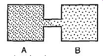
Fig. 7 The movement of molecules from one vacuum container to another
(of greater vacuum) is statistically random.
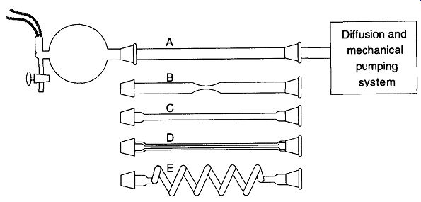
Fig. 8 Transport of gases through tubes of different lengths and diameters.
From Glassblowing for Laboratory Technicians, 2nd ed., Fig. 10.2, by R. Barbour, © 1978 by Pergamon Press Ltd. (now Elsevier Science).
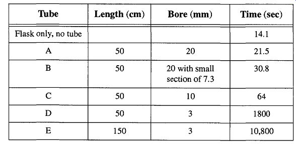
Table 4 The Relation of Tube Length and Diameter to Pumping Time (see
Fig. 8). "From Glassblowing for Laboratory Technicians, 2nd ed., Table
6, by R. Barbour, © 1978 by Pergamon Press Ltd. (now Elsevier Science).
An interesting experiment was done by Barbour with a simple vacuum system of a 5-liter flask connected to a thermocouple with an opening for dry air. The flask was adapted to receive one of five different tubes (of different diameters and lengths) and in turn was connected to a pumping system (see Fig. 8).
Barbour evacuated the 5-liter flask and then filled the system with dry air. He then re-evacuated the flask and calculated the time it took to go from 10^-2 to 10^-3 torr. His results are shown in Table 4. From his description, it is unknown whether he dried and/or pre-evacuated the tubes to decrease the effects of water vapor, which could have slowed the pumping speed somewhat. This slowing effect would have become more pronounced as the surface area increased dramatically such as with Tube E. Regardless, the data effectively show the effects of tube diameter versus length on pumping speed. Be aware that Tube E never achieved 10^-3 torr after three hours of trying to stabilize to the lower pressure.
Inspecting Table 1, the mean free path of a molecule ranged from an estimated 7 to 70 mm for the ranges of this experiment's pressures. Without even getting to molecular flow, the efficiency of Tube D and E compared to Tube A (in cross area) is similar to a 44 lane freeway with only one lane open during rush hour. Another thing to consider is that at 10^-3 torr, with the mean free path at about 7 mm, by going from a 10-mm-i.d. tube to a 6-mm-i.d. tube, flow transport would be slowed considerably. This should serve to show that pressure and tubing i.d. is interrelated.
Whether turbulent, viscous, or molecular flow, the fastest transport through tubes is when the diameter is large and/or the length is small. Fortunately, at a certain point, larger diameters or shorter tubes make no significant difference in performance.
2.9 Throughput and Pumping Speed
There will always be a net transport of gas from one end of a system to another if there is a pressure difference between the two parts. The quantity of gas (at a specific temperature and pressure) that passes a given plane in a given amount of time is called the throughput or mass flow rate (0 . When throughput is equal to zero, you have a steady-state condition. Throughput is measured in pressure-volume per unit of time, such as torr-liters per sec or 1 Pa-M3/S = 1 W (watt). Interestingly enough, because force is required to move the gas, throughput can also be considered as the amount of energy per unit time passing through a plane.
A different measurement of gas transport is the volumetric flow rate (S), which is also called the pumping speed. The units of volumetric flow rate are simply volume/time, such as liters per second. The difference between Q and S is that S is independent of the quality of the vacuum. Throughput and volumetric flow are related to each other by the pressure P and are expressed in Eq. (7). The relationship of mass flow, volumetric flow, and pressure is demonstrated in Fig. 9.
S = Q/P ( 7)
In a typical vacuum system, tubes are connected to tubes, which are connected to traps, which are connected to other tubes, and so forth. The transport of gas through a system of these tubes is called conductance (Q. Every tube within the system offers a different conductance depending on its length and diameter.
Conductance is the throughput (Q) divided by the difference between the pres sure going into the tube (P,) and the pressure going out of the tube (P2) [see Eq. ( 8)]. Although conductance and volumetric flow rates have the same units, conductance is used to describe the ability, or efficiency, of a gas flowing through a Fig. 9 A system in a steady-state condition showing the relationship between Q, S, and P. From The Fundamentals of Vacuum Technology, 3rd Edition FIG. 13, by H.G. Tompkins, © 1997 by the American Vacuum Society, American Institute of Physics, New York, reproduced (abstracted) with permission section (one or more) of tubing, while volumetric flow rate deals with the amount of gas that can go past a single plane of the system:
C = Q/(P1-P2) ( 8)
Vacuum systems are generally not made with one tube and one easy way to calculate conductance. Rather, vacuum systems are constructed with many tubes of different sizes. The total conductance of an entire system is calculated by adding all the reciprocals of the conductance of the various parts [see Fig. 10)] and is shown in Eq. (9):
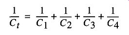
( 9)
What can be seen from Eq. (9) and Fig. 10 is that by placing a stopcock mid-length on a tube will minimally effect conductance, especially if the length of the stopcock section is as short as possible and the size of the stopcock is as large as possible. Common sense, economy, and experience are good guides for this.
Fig. 10 The total conductance is the addition of the reciprocal conductance of all the parts (see Eq. (9).
3. Pumps
3.1 The Purpose of Pumps
A pump's function (when creating a vacuum) is to remove gases and condensable vapors from the chamber where you want the vacuum. There are two ways to remove gases and vapors. The one that typically comes to mind is gas transfer, which physically removes gases and vapors from one area and release them into another. The other approach for removing air is to trap the offending gases and vapors. Once trapped, the vapors are still in the region where you are working but are bound up in such a fashion so as not to impede the work in progress. The two approaches of gas removal, pumps, and corresponding pumping ranges are shown in Table 5.
The most common level of vacuum required to do most laboratory procedures is, in reality, not a very significant vacuum. In fact, a high (=10^-3 torr) to very high (=10^-6 torr) vacuum will satisfy some 95% of most laboratory vacuum needs. The levels of ultrahigh vacuum (whose demands are usually reserved to surface studies, ultraclean vapor deposition, space simulation, and particle accelerators) are not that common in many research laboratories. Thus, in the chemical research laboratory, the pumps that are usually found are the gas transfer type. More specifically, one is likely to see aspirators, diffusion pumps, and rotary vane and/or piston pumps. Although turbomolecular pumps (turbopumps) and cryopumps may also be found in the laboratory, their high initial cost (along with their higher level of technical support), excludes them from being the first pump of choice unless unique requirements demand their use. The other pumps mentioned in Table 5 are usually used in specific industrial or highly specialized research.
With all due respect to these fine pumping alternatives, discussions within this guide are limited to aspirators, rotary (vane and piston) pumps, and diffusion pumps. For further information on the other pumps mentioned, refer to Section D.
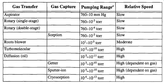
Table 5 Pump Families and Characteristics
These pumping ranges are only general levels, not limits or potentials. There are many factors that can affect pumping range and speed, including the nature of your work and your system's configuration and design.
The concept of "you get what you pay for" can be altered for vacuum pumps to "the less you want, the more you pay." With that thought in mind, you do not want to pay for vacuum you do not need. Note however, that the stated limit of a pump is usually its ideal limit, which is dependent on the type of gas being pumped, the design (efficiency) of the system, and whether the vacuum gauge is connected at the pump inlet. These conditions are unlikely to be like your system, and therefore you should obtain a pump that is rated better than your needs. Again, the onus is on you to recognize what you need. "Keeping up with the Jones'" is generally a good approach to take. If someone has a system like the one you want, ask the person if they are satisfied with their components such as the pump, or, in retrospect, whether the pump should have been bigger or smaller.* Finally, in regard to pump power: Even though you can get a small two-cylinder car to pull a load of bricks, it is more efficient to get a truck. Being pennywise in selecting a pump may be being pound foolish in the loss of wasted time and equipment in the laboratory. For more information on pumping speed, see pages 347 and 363.
3.2 The Aspirator
The aspirator (also called a water-jet pump) is one of the simplest and most economic means of obtaining a vacuum in the laboratory. It has no moving parts of its own (see Fig. 11), uses no electricity, and relies only on moving water to function.
[ Unfortunately, this can also work in reverse if you copy someone's system that is overly built. Of course it will achieve all that they want to do, but so might a system that is smaller and therefore less expensive and requires less maintenance.]
The aspirator is not a very fast pump (1-2 gallons/minute), nor does it create a powerful vacuum (=10 mm Hg) (with proper liquid nitrogen trapping, aspirators can achieve vacuums as great as 10^-2 torr). It is ideally suited for emptying large containers of liquids down a sink or for supplying the vacuum necessary for a filter flask.
Aspirator operation is accomplished simply by attaching the device you wish to evacuate with suitable flexible vacuum tubing to the tube on the side of the aspirator. Then, turn on the water and immediately a vacuum will exist through the vacuum connection tube. The aspirator can operate with water pressure ranging from 10 to 60 lb, depending on design and construction. Generally, the greater the water pressure, the greater the vacuum created by the aspirator. At a certain point (depending on aspirator design) the vacuum potential will level off and no greater vacuum can develop despite increasing the force of the water. Whatever the aspirator design, the vapor pressure of water will always be the upper limit of the aspirator unless some form of trapping is added to the system.
If an aspirator has the appropriate attachment, it can be attached directly to a sink faucet so water exhaust can go down the drain. To prevent splashing that occurs when the water hits the sink's bottom, place a one-half to one-liter beaker under the aspirator filled with water. When the aspirator's water hits the prefilled beaker, the force will be absorbed and no splashing will occur. Otherwise, if the aspirator is going to be used at some location with no adequate drainage, a tube should be connected to the water exhaust so that the water can be channeled to a proper receptacle.
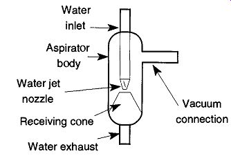
Fig. 11 The aspirator.
The aspirator's pumping mechanism is quite sophisticated, and it all begins by water streaming past the water jet nozzle. By decreasing the internal diameter at the point where the water leaves the nozzle, there is an increase in water speed passing this point. Because the MFP of the gas and vapor molecules within the aspirator is much less than the pump dimensions, aerodynamic shear causes air movement in the desired direction. This air movement will occur regardless of whether there is direct contact of the air with the water or not. Additionally, because the boundary between the rushing water is quite turbulent, air is physically trapped and removed from the aspirator body. In addition, the faster air moves, the less its density. As moving (and therefore less dense) air is removed, nonmoving (and therefore more dense) air is drawn in.
3.3 Types and Features of Mechanical Pumps
There are many mechanical pump designs, the most common of which is the rotary pump. It is named for its use of rotating internal parts that collect, com press, and expel gas from a system. Despite the simplicity in concept, there are very interesting mechanisms that pump manufacturers have developed to over come the problem of mechanical pumps, namely, that they are inherently a slow pump. It is their simplicity, however, that has made them the general workhorse for creating a vacuum all over the world.
There are two different types of rotary pumps: vane (both single- and double vane, see Fig. 12) and piston (see Fig. 13). The vane pump, by definition, uses a spring-backed vane both to separate the atmospheric gases from an evacuated system and to sufficiently compress the gases to a pressure greater than atmospheric so they can be expelled out of the pump. Regardless of whether the vanes sweep in motion (as in the double-vane pump) or remain still and let an eccentric drum roll past (as in the single-vane pump), the vanes permit motion within the pump while maintaining a pressure difference of up to (typically) 10^-3 torr. One of the obvious differences between the double- and single-vane pumps is that the single-vane pump's main rotor spins eccentrically. This eccentric spinning creates a vibration, and if the pump is placed or mounted too close to sensitive instruments, this vibration can affect their operation. The double-vane rotary pump rotates evenly and quietly with little vibration. Pump vibration is important if the pump is mounted in a location that could affect sensitive instruments.
The piston pump, like the single-vane pump, also has an eccentrically rotating drum. However, rather than a vane pressing against the drum, there is a free rotating sleeve around the drum that rolls around the pump's inner cavity as the drum rotates. By rolling around the pump's inner cavity, there is no sliding of moving parts as the vane pumps. Connected to the rotating drum is a sliding shaft with a hole in it that (a) allows air into the pump only when the drum is in the correct position and (b) prevents air coming in at all other times. Properly made piston rotary pumps are counterbalanced so as to have very minimal amounts of vibration.
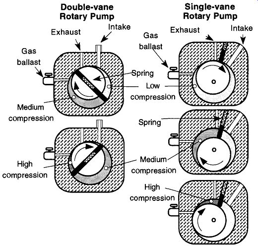
Fig. 12 This series of drawings displays how gas is drawn into single-and
double-rotary vane mechanical pumps, compressed, and expelled into the atmosphere.
There are inherent weaknesses in the design of vane pumps that are overcome with piston pumps. For example, on each sweep of a vane, oil is brought from the atmospheric side to the vacuum side, and needs to be re-outgassed on each sweep.
A piston pump's roller does not sweep oil around. Rather, it rolls over the oil with out pushing it aside, thus significantly reducing the outgassing problem. In addition, the slide shaft (within the piston pump) maintains the internal sections of the pump as two separate sections. This separation further prevents the oils from mixing. Within the pump, one section is maintained at the vacuum of the chamber being evacuated, and the other section is maintained at the pressure for expelling gas into the atmosphere. Because vanes are constantly scraping the internal walls of the pump, extra heat is generated. This heat produces extra wear on the pump, its parts, and the oil. On the other hand, the extra heat helps to outgas the oil to some degree.
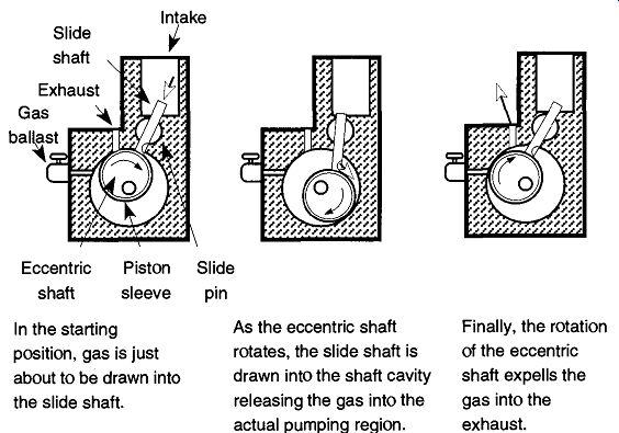
Fig. 13 This series of drawings displays how gas is drawn into a piston
mechanical pump, compressed, and expelled into the atmosphere.
Finally, because the piston does not need to make actual contact with the internal sections of the pump (only contact with the oil is required), there is less wear than with vane pumps. Because the piston pump parts do not make physical con tact, they can tolerate larger-sized paniculate matter (which may accidentally enter the pump) and are also more forgiving of internal scratches.
Rotary piston pump studies made by Sadler demonstrated that the above attributes of piston pump design helped them outperform vane design pumps both in speed and vacuum achieved (Sadler compared pumps of comparable size). On the other hand, piston pumps had greater vibration.
Aside from the two types of rotary pumps mentioned, you will often see the terms single-stage and double-stage mentioned in the context of pumps. A two stage pump (also called a compound pump) simply refers to a mechanical pump that has one or two pumps connected in line together. The exhaust of the first one becomes the intake of the second. The rotors of the two are set in-line so that they use the same shaft.
A two-stage pump can usually provide a decade of improvement over a single stage pump (total potential vacuum) and is generally quieter than a single-stage pump [although the use of a gas ballast (see Section 3.5) can increase the noise].
Two-stage pumps typically have a (somewhat) greater purchase price and maintenance cost.
The ultimate vacuum ranges of mechanical pumps are around 10^- 3 to 10^-4 torr. However, remember that the "ultimate pressure" of a given pump is dependent on pump conditions, system design, system conditions, and the gas being pumped.
Regardless of the type of mechanical pump design, neither the pumping mechanism nor the vapor pressure of the oil is the limiting factor in obtaining low pres sure. Rather, the natural limitation of mechanical pumps is due to the solubility of air (and any other vapors and gases that are being pumped) in the pump oil (for more information on the relationship of pump oils to mechanical pumps, see Section 3.7).
There is not much that can be done about the fact that gases in the oil raises the vapor pressure, and therefore raises the potential pressure obtainable with single stage pumps. However, two-stage pumps provide a solution: by keeping the chamber above the oil in the first stage (on the inlet side of the pump) in a vacuum state, there is less air to saturate the oil. There can be up to 10^-5 torr difference between the inlet of the first stage and the exhaust of the second stage. Thus, a two-stage pump can go beyond the physical limits of a single-stage pump. In addition, two stage pumps fractionate their oil as they work. The oil on the inlet (vacuum) side maintains its purity while the oil on the atmospheric side tends to collect the contaminants and products of oil degradation. This design helps maintain the capability of the pump between oil changes.
The design of two-stage pumps makes them poor choices for pumping air at high pressures (i.e., atmospheric) for an extended amount of time. The excess air pressure tends to cause the oil in both sections of the pump to froth and foam, which in turn may cause the bearings and/or the seals to overheat. Thus, two-stage pumps make poor roughing pumps. It is for this reason that some systems require two mechanical pumps. One pump is a single-stage roughing pump to get a large system (or a system with large quantities of moisture) down to a pressure that a diffusion pump can begin to operate. This system is then joined by a two-stage pump that can deliver the proper fore pressure for the diffusion pump (or other ultrahigh-vacuum pump). The second pump is called the fore pump. If the system is small and can be pumped down to about 1 torr within a minute or two, then the roughing pump and the fore pump can be the same pump. However, if your work tends to cycle between atmospheric and vacuum on a repeated and continual basis, the addition of a roughing pump is recommended.
Pumps can also be divided into direct-drive or belt-driven models. Direct-drive models run faster and quieter, and they are smaller and lighter for the same level of performance. For many years they were not considered able to withstand the workloads of belt-driven pumps because they tended to wear out prematurely. Fortunately, direct-drive pumps have improved considerably over the years.
In their early design, direct-drive pumps simply had the shaft of the motor extended, and a pump was placed on this shaft. Unfortunately, any minor variation in alignment caused excessive wear and tear on the pump bearings and vanes. Inexpensive direct-drive pumps that are in production today still have this inferior design.
Currently, the motor section of the direct-drive pump is connected to the pump section by a coupling. This coupling allows acceptable variations in alignment between the motor and pump, but each component independently maintains their own tight tolerances.
Another holdover from belt-driven pumps that was applied to direct-drive pumps was that the oil was initially gravity fed. Unfortunately, this was not sufficient for the greater speeds of direct-drive pumps, and early designs often suffered premature bearing failure. (Direct-drive pumps typically spin at 1800 rpm while the pump on a belt-drive pump is typically spinning at about 600 rpm.) A small set of blades was added to direct-drive pumps that forced the oil into the pumping region, thereby eliminating the problem.
All of the aforementioned pumps require oil for operation. One of the draw backs to standard mechanical pumps is their propensity toward back-streaming of their oils, causing the potential contamination of the system. Once the pump has achieved its greatest vacuum, its efficiency drops to zero. At that point there is lit- tie to prevent vapors and gases going toward or away from the pump, and back streaming can occur. To decrease or limit the potential for back-streaming, traps and baffles are used.
An alternative is to use a pump that doesn't require oil; these dry pumps have no grease or liquids (oils) in the pumping region. One type of a small dry pump design is the scroll pump. A scroll pump can achieve speeds of about 8 liters/sec and have ultimate total pressures of about 10^-3 torr. The value of these pumps is that because there are no oils in the pumping region, there is no concern about any back-streamed oils getting into the vacuum system.* This means that for any processes that must be kept (oil) contamination-free and where one wishes not to deal with traps and all the accompanying hardware and maintenance, scroll pumps seems like a wonderful opportunity. Be forewarned that these pumps are very expensive and are intended to be cost-effective when compared to the potential costs of trap and baffle maintenance over the life of the pump.
For all pump types or designs, there are three different types of motor housings, each providing different levels of safety. Therefore, the environment that the pump will be used in should also be considered when selecting a pump:
1. Open motors provide an inexpensive housing that is to be used in a clean dry environment (no protection necessary).
2. Totally enclosed fan-cooled motors are used where moisture or dirt is prevalent (protects the motor).
3. Explosion-proof motors are required to meet the National Electrical Code Standards for use in hazardous conditions. These are used where gas, dust, or vapors may be in hazardous concentrations and a spark from the motor could cause a fire or explosion.
The final pump characteristic is pump size. To obtain a pump that is too large and/or too great, a pumping power for a given need can be a waste of money. However, if a pump is not large or powerful enough, there is a further waste of extra money spent when the proper size pump must be purchased. In general, it is better to err too large than too small. A simple formula can be used to aid in the selection of a pump size 14:
S = VxX/t(7.10)
where: S is the pumping speed (liters per minute); V is the chamber volume (liters)
[Among the duties of oils in standard mechanical pumps are those of protection. Since scroll pumps do not have oil, they are dependent upon traps and baffles for protection against gaseous and paniculate contamination. Although back-streaming of pump oils is not a concern from a scroll pump, the need for traps still remains. Ironically, the demands of maintenance on traps for scroll pumps is greater than for regular pumps due to the total lack of protection the pump has for itself.]
t is the time of evacuation desired (minutes)
F is the pump down factor, and is (2.3 x log (760 / desired chamber pressure in torr)), or see Table 6.
For example, if you have a vacuum line of about 20 liters that you wish to bring to 10^-2 torr in 10 minutes, then 20 x 11.2 s = 10 = 22.4 liters/minute
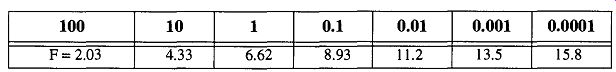
Table 6 Desired Chamber Pressure in torr. From "Vacuum Products" by
Welch Vacuum, Thomas Industries, Inc., p. 125, © 1988 by Welch Vacuum Technology,
Inc.
This determination is assuming that you have a perfectly designed vacuum sys tem with no narrow passageways, no extra chambers, no bends, no contamination, and no traps, baffles, or stopcocks. Not much of a vacuum system, but it sure would be fast. Because you are working in the real world, the real pumping time will be slower. To compensate for this slower time, it can be helpful to multiply the above result by 2 or 3 to ensure that the pump will be adequate to handle your system's needs. However, as a tool for approximating the minimum size needed, the above formula is usually sufficient. The final decision of what pump to purchase, as in all selections, will depend on what you are willing to settle for and/or what you can afford. (More information on pump speeds is provided in Section 3.10.) In many laboratories, the demands on a standard mechanical pump are less critical than in industrial use. A lab is generally more interested in obtaining a low pressure than in the speed and/or volume pumped. Typically, the primary consideration in the laboratory is that the mechanical pump achieves the vacuum required (for example: for diffusion pump operation) in a reasonable amount of time.
Most manufacturers suggest the size of fore pump to be used with their diffusion pump. If you do not have this information, it is possible to match a fore pump with a diffusion pump by using Eq. (11):
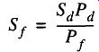
where is the fore pump speed is the fore pump operating pressure
Sd is the diffusion pump speed
Pd is the diffusion pump operating pressure
Whatever you get for the fore pump speed from Eq. (11), it's a good idea to use a pump with at least double that figure to accommodate pressure fluctuations and make up for line impedance within the vacuum system.
In summation, the following suggestions should be considered when selecting a mechanical pump:
1. For table-top demonstrations and/or small experiments, a direct-drive pump is excellent. Its portability, low vibration, and generally quiet operation is important.
2. For general experimentation, large manifold systems, and industrial operations, direct-drive pumps are also strongly recommended. If, how ever, you are pumping a dirty environment, belt-driven mechanical pumps should be considered because their greater oil chambers can better tolerate contamination (see Section 3.7). They can easily be placed in pans (to catch any accidental oil leaks) on the floor, and they can be left on for days and/or weeks of continuous operation.
3. Double-vane pumps have the least amount of vibration.
4. Piston pumps are not made with the same close tolerances as vane pumps, so they are more forgiving for particulate matter developing within the pump oil. They also exhibit greater performance than other pumps of comparable size.
The size of the pump, however, is still up to the needs and demands of the user.
3.4 Connection, Use, Maintenance, and Safety
At first glance, the use of a mechanical pump seems so straightforward that little needs to be said-and for the most part that's true. However, failure to observe some simple rules can result (at least) in inefficient running of the pump and (at worst) pump destruction.
Connection. Always place your pumps in some type of tray so that any leaks will be contained and will not create slick spots.* This placement is especially important if the pump is positioned on the floor. By placing the pump on the floor (and in a tray), any vibration effects from the pump on instruments sitting on lab benches will be limited.
[This is not meant to imply that all pumps leak, and it is extremely unlikely that a new pump would leak. However, old pumps may leak, and any time the pump oil is changed, there is a chance for spillage.]
The most efficient attachment of a pump to a vacuum system is with a tube as short in length and as large in diameter as practical. Unfortunately, it is not uncommon to see five-feet of vacuum hose between the mechanical pump and the vacuum system coiled and doubled over on itself. This setup is not only a waste of tubing, but it may cause a decrease in pumping efficiency.
Pump accessibility is equally important. The sight gauge (see Fig. 15; pump belt, exhaust line, electrical connections, and oil drain should be easily accessible.
If there is any chance that there could be particulate matter coming from the sys tem, filter traps* should be placed at the pump intake.
All exhaust from a mechanical pump should be vented to a fume hood regard less of the room's ventilation quality or the type of pumped gases. Each time you bring new samples into vacuum conditions, your system is pumping at atmospheric pressured Because pump oils have low vapor pressures, and pump oils themselves are considered nontoxic, there is little concern for breathing pump oil mist. However, there may be dangers from trapped vapors within the pump oils. Regardless, there is little reason to breathe the pump oil mist if it can be avoided. Check with the manufacturer or distributor of your pump for an oil mist filter for your pump. If you use a condensate trap, be sure you position your exhaust line so that material does not drain back into the pump (see Fig. 14).
Use. When you first start a mechanical pump, a gurgling noise will sound. This noise is to be expected when a mechanical pump is pumping against atmospheric pressure and should subside in a few seconds to minutes depending on the size of the system. If the sound does not change, several causes may be present: There may be a stopcock (or valve) on the system open to the atmosphere, part of the system may have been broken off, or the lower portion of a cold trap may have slipped off the trap into a Dewar. Gurgling can also indicate that the pump oil is low. If this case applies, the pump should be stopped, vented, and then filled to the proper level. Finally, a somewhat different gurgling sound can be caused by an open gas ballast. Although this situation may sometimes be confused with an air leak, they are different sounds and one should listen to a gas ballast sound to familiarize themselves with that noise. A gurgling noise from a mechanical pump cannot be caused by a minor (or small) leak, so expect to look for a major reason for the noise. (For small leaks, see Section 6 on leak detection.)
[These traps do not significantly affect the flow rate, but without them, destructive wearing of the pump mechanism could result. Contact your pump supplier for filters to fit your specific pump.
This pumping tends to froth the oil, and the addition of an oil mist filter is imperative.]
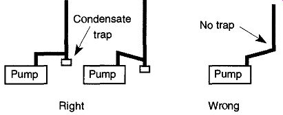
Fig. 14 The proper orientation of a mechanical pump's exhaust condensate
trap. Reprinted from N.S. Harris, "Practical Aspects of Constructing,
Operating and Maintaining Rotary Vane and Diffusion-Pumped Systems," Vacuum,
Vol. 31, © 1981, p. 176, Elsevier Science Ltd, The Boulevard, Langford Lane,
Kidlington 0X5 1 GB, UK.
Before shutting off a mechanical pump, the pump should be vented to atmospheric pressure. Although some mechanical pumps (and essentially all new pumps) have a check valve designed to prevent reverse flow, it is not a good idea to depend on such a valve. If a vacuum is held on the inlet side of a pump with the pump off, the pump oil may be drawn up and into the vacuum line. Therefore, it is best to treat all pumps as if they did not have such a valve. When turning off a mechanical pump, it is best to vent (to the atmosphere) the section of the vacuum line connected to the pump. Your pump should be separated from the rest of the line when venting so that the rest of the line is not exposed to the atmosphere. If the vacuum system is exposed to the atmosphere, it will take longer to re-pump down because moisture from the air will have absorbed on the walls of the system.
Maintenance. Probably the most common problem with mechanical pumps in labs is inattention to the pump oil. More pumps have died because of LSETCOI (Let Someone Else Take Care Of It) than as a result of any heinous intentional act of destruction. The reason is simple: Changing pump oil is not fun or glamorous.
The proper maintenance of a mechanical pump, however, is as necessary as cleaning glassware, keeping a proper lab notebook, and backing up a computer hard disk.
If you are supplied with a used mechanical pump and do not know (or trust) its history, check the oil, both for level and quality. On the side of any mechanical pump is a sight gauge (see Fig. 15). The oil level should be between the "high" and "low" sight lines. If it is too high, some oil should be drained from the pump. If it is too low, some oil should be added.
When examining pump oil quality, it can be beneficial to compare the used oil with unused oil. To do this comparison, keep a small sample of pump oil in a closed jar for inspection. The oil in the pump should be discarded if the oil appears cloudy with a whitish, emulsified appearance, is discolored, or (especially) has tar or particulate flecks.
If you have the facilities to check the viscosity of pump oil, the oil should be about 300 SSU at 100°F (SAE 20 W), + 100 SSU. If the oil's viscosity is beyond that range, it should be changed.
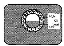
Fig. 15 Check the gauge window on mechanical pumps to see that the oil
level is arlpnnatp is adequate.
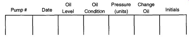
Fig. 16 A suggested log book layout for routine mechanical pump maintenance
in the laboratory.
If you cannot check the viscosity of the pump oil, you should be able to cross check the oil by the current pressure obtained by the pump vs. its fresh (new) oil pressure. If there is a 100-mtorr, or greater, increase in vacuum using fresh oil as opposed to the current vacuum, change the oil. You can maintain a log book (see Fig. 16) of your lab's pump history to have a record of pressure changes over time.
There can be no rule for how often pump oil should be changed. It cannot be done on an "every two to three thousand mile" basis, or even after 20 to 30 hours of operation. It may be necessary to change the oil as often as every day or as seldom as once every several years. It all depends on how often you use your system, what types of chemicals your system is being exposed to, how effective your trap ping systems are, and how effectively you are using your gas ballast (if any) (see Section 3.5). If your system requires an oil change every six months, it does not mean that you only have to check it every six months. Monthly, or even weekly, oil quality checks are advised for any system. A log book, kept in the lab, with sections that note important data (as shown in Fig. 16) will help in lab maintenance. (This log book will also be of value when looking for leaks.) As ironic as it may seem, a pump that is run continuously may require fewer oil changes than a pump that is constantly cycling between atmospheric and vacuum pressures. This condition may be true even if the second pump is run the same number of hours because the cycling pump will be exposed to a greater amount of condensable vapors, which are more likely to severely affect the pump's oil. By continuously running a pump against a load (vacuum) or even better yet, a dry nitrogen leak, the percentage of condensable gases in the pump's oil can be significantly decreased. By removing the condensable gases (especially those that may be particularly corrosive or reactive to the pumps insides) there are less opportunities for internal pump damage.
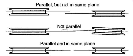
Fig. 17 Alignment of mechanical pump belt pulleys.
[Completely closing the exhaust port can cause the oil to come out in forceful spurts.]
When changing a mechanical pump's oil, first run the pump for a short time to warm the oil. Warm oil will drain more efficiently from the pump. Open the side valve and let the oil pour directly into a container (use a funnel if necessary). If it is physically possible, tipping the pump may speed oil draining, but it should not be required. The pump may retain small pockets of pump oil within small sections of the pump. These pockets can be emptied out by partially* closing the exhaust port and turning the pump by hand. If you start up the pump with a fast click-on and click-off to remove this last bit of oil (as opposed to rotating the pump by hand), the oil may spurt out with surprising force and create a mess.
Return the old oil to where ever used oil is to be returned. Although mechanical pump oil by itself is not toxic, during use it becomes a repository for condensable vapors that may have passed through it. While changing the oil, wear rubber gloves and safety glasses. Never pour used mechanical pump oil down the sink or throw containers of it in the trash. Because the oil could be carrying toxic materials, it should not be sent to a trash dump or landfill. If there are any questions, check with your pump oil supplier, your safety coordinator, and/or your city's Department of Waste Management.
Typically, the new pump oil is poured into the exhaust port, but check with your manual to verify this for your pump. The amount of oil required is dependent on the individual pump and should be stated in the pump manual. If you cannot find the manual and have to "wing it," pour slowly and allow ample time for the oil to show up in the observation port.
If there are any spills when emptying or refilling a pump, clean them up immediately. Pump oils are not toxic, but such spills become slick and slippery and are considered accidents just waiting for someone to walk by.
[A flushing fluid is a special hydrocarbon liquid designed specifically for "flushing out" mechanical pumps. It can be obtained from most mechanical pump, and mechanical pump oil manufacturers and suppliers. Do not use a hydrocarbon solvent, such as acetone because you will destroy your pump.]
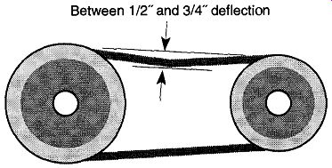
Fig. 18--Acceptable deflection of the pump belt is between 1/2"and
3/4".
Emptying the old oil from a pump and refilling the pump with new oil is generally sufficient when changing a pump's oil. However, if pump oil is particularly filthy, empty the old pump oil and refill the pump with a flushing fluid.* Let the pump run for 10 minutes with the flushing fluid against a load, then drain and refill with the correct oil. A flushing fluid can only be used with hydrocarbon pump oils. Alternately, fill the pump halfway and do not let it run for a minute, but no longer (never partially fill a pump, and let the pump run for any extended period of time). A final alternative to filthy pump oil is to fill the pump up with pump oil and let it run. By alternately plugging and unplugging the inlet for some five minutes, the oil will agitate and aid the flushing of any undesirable materials and/or old oils within the pump. If you use this technique, refill and empty the pump one extra time before refilling the pump for use. After changing the pump oil, be sure to wipe off any oil that may have spilled on the pump, especially the motor. Oil and dirt can prevent the proper dissipation of heat, which could damage air-cooled (or fan-cooled) systems.
Any oil seen around the drive shaft is an indication that a drive shaft seal may need replacement. Unusual noise and/or heat may indicate bearings that may need to be changed or a failure of the internal lubrication system. Typically, the first section of a pump that will show wear from abrasive paniculate matter that may have entered will be the discharge valves and will be indicated with drops in pressure.
If the motor or pump mechanism requires lubrication, typically once a year is sufficient. To lubricate more often than that causes the excess grease to be forced out on the inside of the motor housing, potentially landing on the windings of the motor. This can prematurely destroy the motor.
If you have to change the belt, be sure to align the pulleys both parallel and on the same plane (see Fig. 17). After the belt is on, check its tightness by firmly placing your finger on the center of the belt. The deflection should be between 3/4" to 1/2" (see Fig. 18). If the belt is too loose, it may slip on the pulleys; this causes friction and heat, leading to premature failure. On the other hand, if the belt is too tight, it may break, even within a week of constant use. After a day or two of operations use, recheck the tension because it is likely to have loosened.
Prev. | Next