AMAZON multi-meters discounts AMAZON oscilloscope discounts
(cont. from part 1a)
3.5 Condensable Vapors
A working pump is constantly trapping condensable vapors within the pump oil.
This trapping is caused both by the pump's churning action, which physically mixes the oil and gases, and by the high pressures within the pump during the compression stage of the pump cycle. During the compression stage, the gases and vapors must be brought to a pressure greater than atmospheric before they can be expelled into the atmosphere. Now, by definition, condensable vapors in a vacuum are in a gaseous state. As they are compressed within the pump, some of them may condense out and can mix into the mechanical pump oil. Then, as the veins of the pump continue past the exhaust point of the pump and back to the vacuum side, the condensed vapors can re-volatilize.
The re-volatilization of condensable vapors will decreases vacuum potential by replenishing the vapors in the system you were just trying to remove. This can create an artificially high maximum limit on the pump's potential vacuum. In addition to the backstreaming of vapors, the pump itself is affected when condensable vapors contaminate the pump's oil. Not only will this decrease the vapor pressure of the pump oil, but the condensed vapors can cause a reduction of lubrication and sealing properties of the oil and lead to an eventual corrosion of the pump's internal parts. Other condensed liquids (such as hydrocarbons) can mix, emulsify, and/or break down the pump oil. They can also directly destroy a pump by chemical attack, or indirectly, by poor pump performance, they can cause extra wear and tear on the pump parts.
There is no one good way to prevent condensable vapors from affecting a mechanical pump. There are, however, two directions that one can take in dealing with the problem: One is to limit them from getting to the pump, the other is to prevent them from affecting the pump once they are present. Neither is the best approach, and usually it takes combinations of the two to deal effectively with the problem. An alternative approach is to constantly change the pump oil. This solution however, is neither cost- nor time-effective.
To prevent (or limit) condensable vapors from getting to a pump, traps [either of chilled or chemical design (see Section 4 on traps and foreline traps)], are used.
Depending on the type of trap used, there are opportunities for vapors to pass on to the mechanical pump. Thus, one cannot depend fully on traps of any kind, and one must also deal with vapors at the pump itself.
To prevent (or limit) condensable vapors that reach a pump from affecting the mechanical pump oil, a gas ballast (also called a vented exhaust) is used. The gas ballast allows a small bit of atmosphere (up to 10%) into the pump during the compression stage so that the gas from the system is only part of the gas in the pump at the time of greatest compression. Thus, at the time of compression, the total percentage of condensable vapor within the pump is much less than there would be otherwise. Because the gas prior to being expelled is at a lower pressure, less of the vapor can be compressed into a liquid. Then, as the veins sweep into the vacuum side of the pump, no condensed vapor can expand back into a vapor.
Ballasting decreases the potential vacuum a pump could normally produce (about one decade of performance capability*). However, it dramatically improves its performance over the long run in the presence of condensable vapors. Plus, it helps to protect pump oils from contamination, which decreases pump breakdown possibilities and increases the longevity of the pump oils. Incidentally, running a pump with a ballast causes the pump to run a bit hotter than it otherwise would, which decreases the potential gas-carrying ability of the oil.
If you can obtain 10^-3 torr without a ballast, you may only be able to obtain 10^-2 torr with a ballast.
[If you are not obtaining expected performance and you have a ballast, you may want to check if the ballast was inadvertently left open.]
For maximum efficiency, a gas ballast should be open when first pumping on a vacuum system, or when pumping a system that has (or is creating) condensable vapors. Once sufficient vacuum has been achieved and the majority of condensable vapors have been removed from a system, the gas ballast can be closed, although it does not hurt (beyond ultimate pump performance) to leave a ballast open all the time.
Although gas ballasts can be found on both single- and double-vane pumps, as well as piston design pumps, they are more likely to be found on double-stage pumps than on single-stage pumps. It is interesting to note that a vane pump tends to run noisier with the gas ballast open, whereas a piston pump tends to run quieter with the gas ballast open.
When work is over, there is a tendency to turn everything off. Normally this approach is proper. However, it is better to leave a mechanical pump on (ideally pumping against a dry nitrogen purge) after regular use. The purge should be held at about 300(x for as long as a day to help "flush out" any condensate from the pump oil. This extended pumping will not help pump oil already broken down, but it will help decrease any more pump oil from further destruction by expelling any remaining contaminating material. It also helps to remove water vapor from the pump oil. When letting your pump run for such an extended period of time, always let the pump pull against a load. In other words, never let a pump run with the inlet open to atmospheric pressure because the pump oil will froth and lose its protective characteristics-which can ruin the pump.
You can make a dry nitrogen leak fairly easily. Take a copper tube with fittings to go between a compressed nitrogen tank and the vacuum system, and smash about two inches of the tube flat with a hammer. You can check the quality of your "leak" by attaching this tube to the nitrogen tank, and open the main valve. Place the other end in a container of water and observe the gas bubble formation as you increase the delivery pressure. Sufficient pressure to produce a bubble every 10 seconds or so will provide an adequate leak for a good flushing. Certainly not high-tech, but it seems to work quite well. This can be used not only to help flush out condensable gases from a mechanical pump, but also to flush out a vacuum line of contaminants (provided that the vapor pressure of the contaminants can be achieved with the extra pressure of the dry nitrogen leak purging into the system).
There is an alternate approach to preventing condensable vapors from entering mechanical pump oils-that is, maintaining the pump at relatively high temperatures. The high heat prevents the vapors from condensing within the pump despite the high pressure. However, due to the inherent dangers of this type of pump, as well as the problem that pump oils begin to deteriorate after being maintained at high temperatures, this approach is seldom used.
3.6 Traps for Pumps
All pumps should be protected from materials within the system, the system should be protected from all pump oils, and a diffusion pump (if any) should be protected from mechanical pump oils in the foreline. These protections can be achieved by using traps. More information on traps is presented in Section 4, but the following information is important for general operation.
Any water or hydrocarbon solvents left from previous operations should be removed from traps before beginning any new vacuum operations. Otherwise, any materials in a trap when first beginning operation will be drawn directly into the pumps, which is what the traps are trying to prevent. Having no material in the traps to begin with removes this possibility.
A buildup of water or hydrocarbon solvents during operation can decrease, or cut off, throughput of gas through a trap. If this situation occurs, close off the trap from the rest of the vacuum line and pump. Once isolated, vent the trap to the atmosphere^ let the trap come to room temperature, remove the lower section, and empty the trap. In some cases it may be necessary to remove the trap before it has thawed and place it within a fume hood to defrost. It is a good idea to have some extra lower sections of cold traps to exchange with one that is being cleaned to limit your downtime. If you expect to remove frozen trap bottoms often on a glass system, it may facilitate operations if O-ring joints are installed on the sys tem rather than standard taper joints because O-ring joints are easy to separate, even if the trap is cold.
Cold traps must be used if mercury is used in your system (such as manometers, diffusion pumps, bubblers, or McLeod gauges) and if your mechanical pump has cast aluminum parts. Mercury will amalgamate with aluminum and destroy a pump. Even if your mechanical pump does not have aluminum parts, the mercury may form a reservoir in the bottom of the mechanical pump, which may cause a noticeable decrease in pumping speed and effectiveness. Aside from a cold trap between the McLeod gauge and the system, place a film of low vapor pressure oil in the McLeod gauge storage bulb. This oil will limit the amount of mercury vapor entering the system that makes its way to the mechanical pump.
In addition, an oil layer should be placed on the mercury surface in bubblers and other mercury filled components.
When first starting up a vacuum system, let the pumps evacuate the system (if starting up the system for the first time) or the traps (if they have been vented to the atmosphere) for a few minutes* before setting the traps into liquid nitrogen.
Otherwise you are likely to condense oxygen in the traps and create a potentially dangerous situation when the pumps are turned off (see Section 4.3).
[
The foreline is the section of the vacuum system between the high-vacuum pump (i.e., diffusion pump) and the fore pump (i.e., mechanical pump).
Traps should always have stopcocks or valves on both sides and should also have a third stopcock or valve to vent the trap to the atmosphere to allow removal of the trap. This allows the trap to be disassembled without exposing the system or the pump to the atmosphere.
When a pump is working against a no-load situation, it is often louder than when it is pumping against a vacuum. You can use the volume change as a guide as to when it is safe to begin using liquid nitrogen.
]
3.7 Mechanical Pump Oils
In this section on mechanical pumps, constant attention is placed on the protection and/or maintenance of pump oils. This is because of the incredible demands placed on these oils. Ideally, all mechanical pump oils should:
1. Be thermally stable
2. Be chemically inert
3. Exhibit a low vapor pressure over a wide temperature range
4. Lubricate
5. Maintain the same lubricity and viscosity over a wide temperature range
6. Maintain a vacuum seal between sections
7. Cool heated sections of the pump
8. Trap vapors and paniculate matter from the vacuum system
9. Be compatible (and not interfere) with the environment and provide protection from the environment
10. Be nontoxic
In addition, mechanical pump oils can be specialized for use in specific environments such as those with high-oxygen contents. Some are blended for use in specific types of pumps such as direct-drive pumps, belt-driven pumps, and rotary piston pumps. As with most things, no single product fits the bill for all circum stances. Thus, there are many varieties, grades, and types of mechanical pump oils.
[Regardless of the pump oil used, the vapor pressure of a pump oil (off the shelf) is seldom the limiting factor in the potential vacuum a mechanical pump can achieve. For example, when diffusion pump oils are used in mechanical pumps, they tend to exhibit a decreased ability to pull a vacuum due to the partial pressure of the dissolved gases within the pump oil. Thus, due to the heat of the pump and contamination in the oil, the vapor pressure of the oil can be greater than its stated pres sure by a factor of 10 to 100.]
Various manufacturing processes produce oils with different characteristics. Each of these characteristics varies the oil's tolerance of what it can withstand and still provide safety and protection to the pump. Among the properties that can be altered and enhanced are:
1. Molecular weight: It is better to have a highly refined fluid composed of a narrow range than to have a wide range of molecular weight.
2. Vapor Pressure: Although the vapor pressure of an oil itself is seldom a limiting factor of what the vapor pressure in use will be, it still provides a benchmark level to compare various oils.*
3. Pour point: This property is critical if the pump will be used in cold environments. An oil with too high a pour point could prevent a pump from starting and require the pump to be artificially heated to begin operation. On the other hand, an oil with too low a pour point may burn off if used in too hot an environment.
4. Viscosity: Pumps with tight tolerances, such as vane pumps, require a low viscosity oil, whereas pumps with low tolerances, such as piston pumps, require a higher viscosity oil.
5. Fire point: Any pumping of pure oxygen (or a high percentage oxygen mixture) can cause most oils to explode or degrade rapidly. Therefore, pumping these materials requires a very high (or nonexistent) fire point.
With all the varieties of mechanical pump oils available, there is one further complication: Pump manufacturers are selective about the oil that goes into their pumps. Most pump manufacturers want to sell you their brand of pump oil(s).
This tactic is not so much greedy as it is an attempt to ensure that (what they feel is) a high-quality oil goes into (what they believe is) a high-quality product. It is the best way they have to prevent you from destroying your pump. If there are any questions about the selection of pump oils, check with your pump's manufacturer.
The manufacturer usually would rather help you for free than have one of his or her pumps look bad-even if it is your (the user's) fault! However, be warned: If you place a non-approved oil into a pump, a manufacturer can void any warranty associated with the pump! If you have been advised to use a pump oil on a new pump that is different than what the operating instructions recommend, be sure to find out (in writing) what effects this oil may have on the warranty.
There should be no problem when changing pump oils to remove the old, and simply replace it with a fresh amount of the same oil. However, it is not always possible to simply pour one type out and pour a different one in. Some mechanical pump oils are specifically designed for specific pump designs, while others are designed for specific gas types and conditions. Likewise, you may need to change pump oil types when changing a pump's service to a different type of service (e.g., standard vacuum pumping to oxygen pumping). Depending on the intended service, it may be necessary for a pump to be returned to the manufacturer and rebuilt. For example, if you need to pump pure oxygen, a mechanical pump must be altered at a factory. This alteration will include changing the lubricating oils in the bearings and seals; if this is not done, an explosion could occur. In addition, because some oils are more viscous than others, the pump may need alteration to increase or decrease clearances between parts.
Just like auto engine oil, mechanical pump oil breaks down and needs to be replaced. And, similar to synthetic auto engine oils, mechanical pump oils should be replaced over a period of time, even if they have not broken down. Although the quality of an oil may not have diminished, replacing old oil also removes particulate matter and collected chemicals. Paniculate matter, if soft, can turn pump oil into a gel. Because the viscosity of this gel will be greater than the original oil, the pump will be operating at a higher temperature and is more likely to fail. Hard paniculate matter can scratch the insides of a pump, causing leaks and decreasing performance potential. Chemicals typically get trapped in a pump by entering as vapors that were not stopped by a trap. Vapors in the vacuum state will condense out during the compression stage within a pump (using a gas ballast can limit the effects of this occurring). Once condensed out, a condensed chemical's vapor pressure can be sufficiently high to lower the pump's efficiency. Condensed vapors can also react with pump oil to form gum deposits or simply degrade the oil. In addition, although pump oil may be impervious to acids, the pump containing the oil is not likely to be as resistant. Thus, if your work produces acid fumes, periodically test the oil's pH.
Direct-drive pumps can successfully run with less oil a they are designed to be used with. This is because their internal oil pumps successfully force oil into operating parts that would otherwise be insufficiently fed by gravity in a belt-driven pump. However, it is not wise to depend on this approach to pump maintenance because, as discussed in the beginning of this section, pump oil does more than just the lubrication of parts and maintenance of the vacuum seal between moving parts. Pump oil is also used to cool pump sections and trap vapors and particulate material. Therefore, it is certainly not wise to run a direct-drive pump with less than manufacturer's recommended oil volumes on an actively used vacuum sys tem. If your vacuum system has particularly large concentrations of vapors, it may be better to use a belt-driven pump because of their greater oil capacity. A given amount of contamination in the larger oil tank of a direct-drive pump results in a smaller percentage of contamination.
3.8 The Various Mechanical Pump Oils
There are five primary types of mechanical pump oil.* The advantages and disadvantages of these various materials are explained below and in Table 7.
The Hydrocarbon Oils. These oils are the most common and least expensive. They are composed of paraffinic, naphthenic, and aromatic hydrocarbons and pro vide excellent sealing qualities. When these oils are properly distilled, they can exhibit low vapor pressures (10^-4 to 10^-6 torr). However, they oxidize quickly when heated, have a tendency to form sludge and tars, and are likely to foam if pumping against atmospheric pressure (as opposed to a vacuum).
By fractionating (or vacuum-distilling and double vacuum-distilling) the oils,* finer grades have been developed that exhibit widely varying properties. Further more, oils from different geographic locations have different (both good and bad) properties. Blends of these oils can create new oils of wildly varying compositions and qualities.
[Despite their high success in diffusion pumps, the silicone oils do not have the lubricity characteristics that are required for use within mechanical pumps. Some mechanical pump oils with a silicon base have been formulated, but they have not exhibited any improvements over other oils currently in use. Vacuum-distilled grades are often called mineral oils.]

Table 7 Mechanical Pump Oil Types
Many of the negative properties of hydrocarbon oils can be overcome by the use of additives which "inhibit oxidation, reduce foaming, disperse contamination, 1 ft reduce wear, depress the pour point, and increase the viscosity index." On the other hand, these additives tend to increase the vapor pressure of the oil. Some manufacturers add a coloring agent to the oil that neither helps nor hinders the oil, but such oil may have a more appealing appearance.
Fortunately, most standard mineral oils work extremely well for a wide range of work. Although they are more likely to break down, especially in harsh environments, their relatively inexpensive costs make them easy to replace. Because some conditions will cause a hydrocarbon oil to change into a tar, there are flushing fluids available that help to remove tar deposits when changing the oil. In addition, flushing fluids help remove particulates and improve the removal of vapors remaining after draining the original oil. Flushing fluids can only be used on hydrocarbon oils.
The Phosphate Ester Oils. These oils react slowly with water and therefore require more frequent changes than hydrocarbon oils. These oils are considered fire-resistant, not fireproof. Before the advent of the fluorocarbon oils, they were used for oxygen-rich environments.
The Chlorofluorocarbon Oils (CFCs).* These oils are nonreactive, do not form tars, do not break down, and are nonflammable; therefore they can be used in pumping pure oxygen. On the other hand, they have greater viscosity changes with temperature than do most other oils. In cold temperatures the viscosity can be great enough to prevent a pump from starting. In addition, if these oils (such as HF fumes) are subjected to temperatures greater than 280°C, highly toxic fluorine compounds are produced. As an extra safety precaution, there should be no smoking anywhere near pumps using CFCs. It is easy for a contaminated finger to pass a CFC onto a cigarette, which in turn will be burnt and inhaled! The chlorofluorocarbon oils should not be used with any pump that may have aluminum components (if in doubt, check with the manufacturer). A momentary seizure of an aluminum part can cause a highly localized temperature increase, which, when in contact with a chlorofluorocarbon oil, can cause an explosion.
Incidentally, thermocouples can be affected by CFCs and display a reading three to five times greater than the real pressure. The gauge itself is not affected because the difference is due to the greater thermal conductivity of a CFCs to air. The user needs to divide the thermocouple reading by a factor of three to five to obtain actual pressure.
The Perfluorinated Polyether Oils (PFPE). These oils are the most expensive oils available. They are extremely nonreactive, do not form tars, do not break down, are nonflammable, and can therefore be used in pumping pure oxygen.
If these oils are subjected to temperatures greater than 280°C, highly toxic gases (HF) can be produced. Therefore, there should be no smoking anywhere near pumps using PFPEs. It is easy for a contaminated finger to pass a PFPE onto a cigarette, which in turn will be burnt and inhaled! The excellent stability of these oils creates a new problem. Among the duties of pump oils is trapping vapors and particulate material from a system. Acids and particulate matter remaining within a pump oil can destroy a pump, even though the oil itself may be in fine condition. Fortunately, PFPE oils can be purified (reclaimed), which dramatically decreases the high initial costs of these fluids.
Therefore, proper changing schedules, using fresh oil, do not necessarily mean a tremendous increase in cost beyond your original investment.
[* The acronym "CFC" stands for all chlorofluorocarbons, including those that are specifically harmful to the environment and those that are considered benign.]
3.9 Storing Mechanical Pumps
If a mechanical pump is going to be unused for any length of time, the pump oil should be changed before storage. Although a small concentration of contaminants are not likely to affect a pump over a short period of time, damage can occur with prolonged exposure. By removing the old oil, any potential contaminants are removed and will not be capable of damaging the pump interior. If the pump will be disconnected from a vacuum system, the inlet and exhaust tubes should be plugged with neoprene stoppers (typically colored green, see Section 1.3.2). Natural rubber stoppers are more likely to disintegrate, and a cork may crumble, allowing particulate materials into the pump, which could damage it once it is restarted.
3.10 The Limitations of Mechanical Pumps and the Demands of High-Vacuum Pumps
At 10^-3 torr, mechanical pumps have effectively remove =99.99% of the air from a vacuum system. The last 0.01% is a combination of outgassing (mostly water vapor) and leaking. Considerable water vapor clings tenaciously to the walls of a vacuum system and is removed slowly. Hablanian (20) describes a specially designed vacuum system that is specially baked and trapped and is capable of achieving inlet pressures of =10^-8 torr with a mechanical pump. In a test designed to investigate more practical approaches to "getting the most out of a mechanical pump on a glass vacuum system, Strattman tried a Micromaze trap from the Kurt J. Lesker Co. Once the trap had been effectively baked, he was routinely able to achieve pressures of 10^-5 torr. (There is greater discussion of Strattman's work later on.) Selection of pump size is typically based on the speed that the pump can move gas. A small mechanical pump has pumping speeds ranging from about 0.03 to 0.33 liters/sec,* whereas a medium pump's speeds range from about 11.7 to 25 liters/Section Large mechanical pumps have speeds ranging from about 50 to 83 liters/Section Regardless of pumping speed, the ultimate pumping capability of small, medium, and large mechanical pumps ranges from 10^-2 to 10^-4 torr. It is important to remember that can a bigger pump does not necessarily mean better pumping--it does mean faster pumping. Consider also that pumping speed is not constant as the pressure drops. Two-stage pumps can provide faster pumping at similar lower pressures than single-stage pumps. Regardless, when either pump has reached its ultimate vacuum, pumping speed goes down to zero.
If you have a large-volume system or if your system creates large quantities of gas, you need a larger pump. However, don't get a big pump and expect a greater vacuum. What you can get with a bigger pump is the ability to achieve the same level of vacuum in a faster time.
[The speed ranges indicated here are based on different pumps, not ranges of efficiency of one pump. That is, a small, small pump's speed is about 1.5 liters/m, but a big, small pump's speed is about 20 liters/m.]
In vacuum company catalogues, one might see claims of their pumps total pres sure and partial pressure capabilities. The partial pressure listing typically shows a better vacuum capacity than the total pressure because it is excluding condensable gases (thereby being a "partial" sample of the whole "total" pressure). For standard use, consider the listed ranges of the total pressure. It is unlikely (especially in a glass vacuum system) that you will be able to exclude condensable gases.
As stated, a medium mechanical pump can only have speeds of 11.7-25 liters/ Section However, a comparable-sized diffusion pump can achieve speeds of up to 30 liters/sec, but with 2-3 times the vacuum capacity. It is easy to see why the assistance of an auxiliary pump is required to effectively obtain vacuums beyond 10^-4 torr, such as those in the high or even ultrahigh-vacuum range. Although it is possible to obtain larger and faster mechanical pumps, the cost/efficiency ratio starts to go down and it becomes less expensive to use a mechanical/diffusion pump combination.
Cryogenic and turbo pumps are known for their cleanliness and effectiveness. However, these pumping systems are very expensive and require significant training for proper operation. The most common auxiliary pump used in the laboratory is the diffusion (or vapor) pump.
3.11 Ultra-High Vacuum Levels Without Ultra-High Vacuum Pumps
As stated, one of the reasons for using a vacuum is to remove oxygen from a sys tem so that air-sensitive compounds will not react. If that is your primary concern and you do not need to use cryogenic transfer for movement of compounds within the vacuum line, there may not be a need to equip your lab with an ultrahigh-vacuum system.
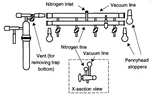
Fig. 19 Standard Schlenk line.
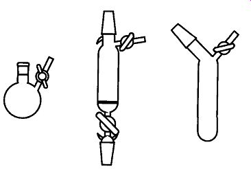
Fig. 20 Some Schlenk apparatus items.
Most commonly known as a Schlenk line (see Fig. 19), this vacuum line/apparatus allows easy evacuation and purging of Schlenk items (see Fig. 20). The concept for Schlenk procedures is very simple: One simply evacuates an item connected by a thick-walled tube to the bottom of the three way stopcock. Then by simply rotating the stopcock 180°, it can be refilled with dry nitrogen. Using several more repetitions of this evacuate and purge procedure, oxygen concentrations can be brought to relatively low levels.
Assuming there are no leaks, the remaining portion of atmospheric gases can be shown to be
Af = f^n ( 12)
where:
Af is the fraction of gases remaining after evacuation
n is the number of evacuate and purge repetitions
To demonstrate the value of this system, suppose you have a mechanical pump who's general lower range is 2 torr (in an acceptable pumping time period*). By the third evacuation and purging, the amount of residual air is 2 x ( 2 /760) 2 , or about 10^-5 torr.
I strongly encourage anyone seeking more information on Schlenk lines and other oxygen sensitive chemistry to examine The Manipulation of Air-sensitive Compounds by D.F. Shriver and M.A. Drezdzon (Wiley-Interscience, © 1986).
[That is, prolonged evacuation could create a better vacuum, but, as is shown, the prolonged pumping isn't time-effective.]
3.12 Diffusion Pumps
A diffusion pump (also called a vapor pump) has no moving parts, yet is considered a "fast" pump. By itself, the diffusion pump cannot move gases from one place to another. However, under specific conditions, it can compress gases to a specific region within itself. Used in tandem with an auxiliary pump (such as a mechanical pump), these compressed gases can be expelled out of the system. Interestingly, it is the same auxiliary pump that removes these compressed gases that creates the specific conditions for the diffusion pump to work.
The basic principle of a diffusion pump can be explained with a simple single stage mercury diffusion pump (see Fig. 21). On the system side of the pump (at about 10^- 2 to 10^-3 torr, or better), gas molecules wander around, limited by their mean free path and collisions with other molecules. The lowest section of this dif fusion pump is an electric heater that brings the diffusion pump liquid up to its vapor pressure temperature.* The vapors of the diffusion pump liquid are vented up a central chimney where, at the top, they are expelled out of vapor jets at super sonic speeds (up to 1000 ft/sec). Below these jets is a constant rain of the pumping fluid (mercury or low vapor-pressure oil) on the gases within the vacuum system.
Using momentum transfer/ gas molecules are physically knocked to the bottom of the pump, where they are trapped by the vapor jets from above. Finally, they are collected in a sufficient quantity to be drawn out by the auxiliary (mechanical) pump.
The upper pressure range for a diffusion pump to operate is limited by the vapor pressure of the heated oil (or mercury) at the jets. Unless the second pump can achieve this pressure (assisted by the decreased pressure within the system), the diffusion pump will not operate.
Pumping speed within a diffusion pump is proportional to the area being pumped. When diffusion pump vapors are traveling their fastest, they can make the pump, pump faster. Unfortunately at these greater speeds, they have the least compression ratio, which means that the collected gases may not have sufficient pressure to be drawn out by the fore pump. By shaping the insides of the diffusion pump accordingly (i.e., a larger space around the first stage and succeedingly less annular space around subsequent stages) engineers can manipulate the vapors of the pump to get the best of both worlds. The design for a typical metal three-stage pump can be adapted to glass as seen in the unique Wheeler pump in Fig. 23.
The more commonly seen "old style multistage glass diffusion pump" can be seen in the pumps shown in Fig. 22.
[Relative to the pressure within the system.
Momentum transfer is possible because momentum = (mass) x (velocity), and the velocity of the diffusion pump fluid (when it leaves the pump jets) is typically at supersonic speeds. Thus, it is easy for the diffusion pump liquid to knock around any size molecule.
For comparison, the diffusion pump in Fig. 23 is a three-stage pump.]
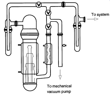
Fig. 21 A mercury diffusion pump. [In a mercury diffusion pump, the mercury
is heated to the point of vaporization. This vapor travels up into the condenser
area where it is ejected at supersonic speeds from little holes. The vapor
knocks any wandering gas molecules down toward the mechanical pump outlet
which can then expel them from the system. The vapor later condenses and
collects in the heating pot for reuse.]
The diffusion pump in Fig. 21 has only one jet.* By definition, this design would be called a single-stage pump. Metal diffusion pumps can have from one to six stages, whereas glass diffusion pumps can have one to three stages. Pumps with several stages allow each stage to be aided by the work of the preceding stage. The first stage (at the inlet of the pump) can offer a high pumping speed (but by design cannot have a high compression ratio). Because the gas flow is constant, the next stage does not require the pumping speed that the first was capable of achieving and can therefore provide a higher compression ratio. This process continues so that the lowest stage (which has the lowest pumping speed) provides the highest compression ratio. This high compression allows the collected gases to be at a sufficiently high pressure for removal by the fore pump.
Diffusion pumps can be made out of glass or metal. Metal diffusion pumps are more durable, can be made to more exacting standards, and therefore can provide a more consistent vacuum within each design. Metal diffusion pumps can be (reasonably) easily removed from a vacuum line and be completely dismantled for cleaning. They are designed to be attached to metal vacuum systems. To attach a metal diffusion pump to a glass system, a glass to metal flange is required.
If ordering such a flange, be careful that you order a glass that is compatible with the glass on your system. Most glass systems are made out of Corning (Pyrex [7740]), Kimble (Kimex [KG-33]), or Schott (Duran [8330]) glass. A glass-to metal flange using any one of these glass types is compatible to any other. The metal of the flange may be stainless steel (machined to receive any of the three above-mentioned glasses), or Kovar, which is an iron, nickel, and cobalt alloy.
The glass sealed to this alloy will be either Corning 7052, Kimble K-650, or Schott 8250 glass. Like the earlier triad, these three types of glass are compatible with each other, but none of these three can successfully be sealed to the former three glasses. If, for example you attached the Corning 7052 to 7740, the seal would crack due to the difference in coefficient of expansion between the two.
There must be a third glass (forming a graded seal) between the borosilicate glass and the glass fused to the Kovar.
When purchasing a glass to metal flange, the catalogue will identify the type of glass attached to the metal. It will be either one of the former three glasses (implying a graded seal has already been made) or one of the latter three (necessitating some attachment decisions). Therefore, be sure you know what type of glass you need before ordering a glass-to-metal flange.
For years, glass diffusion pumps provided (relatively) easy attachment to a glass vacuum system (but rather difficult removal), are mostly free from attack by corrosive substances, provide easy observation of the materials inside the pump, and can be cleaned (with some difficulty).
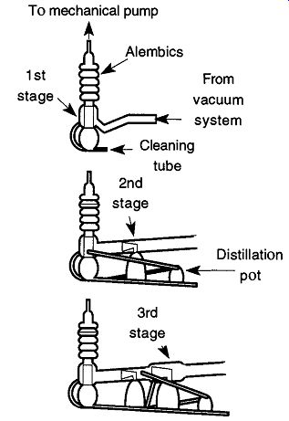
Figure 7.22 displays three different traditional designs of glass diffusion
pumps (that use low-vapor-pressure oil). These three designs demonstrate
the addition of stages. They are also among the most commonly seen diffusion
pump designs.
Although the three pumps shown are all air-cooled, it is possible to obtain most small diffusion pumps as air- or water-cooled. The advantage of an air-cooled dif fusion pump is that there is no water hose connection to slip off the pump and no overheating occurs if the building water is shut off without warning. However, in a warm, nonventilated room, air-cooled diffusion pumps can lose their efficiency. Water-cooled pumps work efficiently regardless of room conditions.
The data in Table 8 show that the addition of stages dramatically increases the speed of a pump while only moderately affecting the net vacuum potential.
However, the speeds listed were determined in 1965 and were ostensibly derived from a vacuum gauge placed at the inlet end of the pump. For one thing, this location provides the best potential vacuum that can be expected from any system and is not likely to represent what would be found on any vacuum system. However, more significantly, new research initiated by Strattman (and performed at Varian) has created a significant controversy on the merits of the single-stage glass diffusion pump of the design shown at the top of Fig. 22. Varian found that this design had no pumping capabilities whatsoever because it had a pumping speed of essentially zero. With that in mind, all the other speeds presented in Table 8 are suspect.
Strattman quotes Hablanian, stating that this single-stage pump design was created by Gaede in 1915 and later shown to be inefficient by Donouyer in 1922. A more viable design was created by Langmuir in 1928 by implementing jets into the design. Although popular (probably by its simplicity in design), it is at best assisting the mechanical pump by limiting backflow of mechanical pump oil vapors. A diffusion pump requires a boiler that can obtain a pressure of at least 1 torr and a jet to accelerate the vapors. If this pump had a jet arrangement added, it could theoretically obtain a pump speed of approximately 1 liter/m.
On the other hand, Snyder, using a different independent testing lab, came up with results comparable to the results presented in Table 8. There are a variety of possible explanations for this, including measuring different parameters, one pump design is better than the other, improper fluids, or improper pump instillation. It appears that despite the simplicity of design, more analysis needs to be done to fully appreciate the value (or lack thereof) of the single-stage glass diffusion pump.
Fig. 22 Various forms of glass diffusion pumps. The potential speeds and
ranges of glass diffusion pumps are shown in Table 8. From Journal of Chemical
Education, 42, pp.A445-A459. (1965).
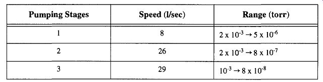
Table 8 Glass Diffusion Pump Capabilities
One of the problems in analyzing the speeds of any glass diffusion pump is the fact that all diffusion pump construction is handmade by a glassblower. There is no question that the vast majority of diffusion pumps one may purchase are of excellent quality. It is also true that construction can vary from one pump to another by the same glassblower and can vary considerably from glassblower to glassblower. Intentional alterations such as a design tweak here, an alteration there can subtly or significantly affect the potential quality of the pump. Likewise, unintentional shape alterations can equally affect the potential of a glass diffusion pump.
A newly designed glass diffusion pump by Michael Wheeler has eliminated most of the problems of the classic glass diffusion pump design while consider ably improving the pumping capacity. The pump (see Fig. 23) was a direct copy of a metal three-stage pump, and was intended to assist teaching the operation of the metal pump. Remarkably, the pump performed better than the metal pump it was copied from. Aside from speed (the operational pumping speed of this pump was determined to be an impressive 188 liters/s), the pump provides easy attachment and removal from a vacuum system, easy to remove internal components for cleaning, and external heating via a heating mantle. This latter point is important because it eliminates the through-glass electrodes of the classic design that are easily susceptible to breakage. Consistency of pump manufacturing is enhanced by the pump's design plans that Wheeler provides to anyone who wants them.
Quality of manufacturing is still dependent upon the quality of the glassblower.
[ University of Arizona, Department of Chemistry.
Because glass is less susceptible to chemical attack than metals, it may be desirable to use components whenever possible.]
3.13 Attaching a Diffusion Pump to a Vacuum System
As previously mentioned, a diffusion pump works in tandem with a mechanical pump. The simplified alignment of such a system should be considered: vacuum line, diffusion pump, mechanical pump. However, in reality, the setup is a bit more complex.
1. A trap (i.e., a liquid nitrogen trap) must be placed at the inlet (system) side of a vacuum line to trap any vapors coming from the line as well as any lighter fractions of the diffusion pump fluid (see Section 4 on traps for the proper alignment and use of traps on a vacuum system).
2. The tubing between the vacuum system and diffusion pump must have as few restrictions (in size and shape) as possible. Glass or rotary stop cocks with bores from 12 to 15 mm minimum (on the system side of the diffusion pump) will help to ensure minimum hold-up. In addition, tubing in these areas should be as straight (unkinked, with few bends) as possible.
3. Because the pressure on the fore side of the diffusion pump is consider ably higher than the pressure on the system side, large-bore stopcocks are not necessary and a stopcock with a bore of 8 to 10 mm is sufficient.
4. Oils used in mechanical pumps have significantly higher vapor pressures than the oils used within diffusion pumps. Therefore, it is important to prevent backstreaming of mechanical pump oils into the diffusion pump. This barrier can be done either with liquid nitrogen cold traps, molecular sieves, water-cooled thimbles, or chevron baffles.
5. A vacuum system needs to achieve a sufficiently low pressure before the diffusion pump can begin operation. A mechanical pump that works in tandem with a diffusion pump is called a fore pump. Fore pumps must be capable of achieving =10^-2 -10^-4 torr and have sufficient speed to effectively work with a diffusion pump.
Most mechanical pumps with sufficient speed and ability are two stage pumps. However, it is not good to run a two-stage mechanical pump for an extended period of time without pulling on a load. Therefore, a fairly large system that would require running a mechanical pump for over 5-10 minutes before a =l-torr vacuum was achieved should include a smaller roughing pump. Once the vacuum has been "roughed" down, the fore pump can be started to bring the vacuum line to a low enough pressure to start the dif fusion pump.
Fig. 23 Wheeler diffusion pump design.
[*Operations that require you to cycle your vacuum line back and forth from atmospheric to low pressure can put significant strain on the fore pump and its oil, so a roughing pump should again be considered.]
Fortunately, vacuum systems in most laboratories are small enough that the fore pump can double as the roughing pump with no problems.* For the few times that one needs to go from atmospheric to vacuum conditions, all that is necessary is to close off the line to the diffusion pump and open the line to the roughing pump. Then, once the pressure is within the range at which the diffusion pump can operate, close the valve to the roughing pump and open the line to the diffusion pump.
A glass vacuum system requires a glassblower to assemble and fuse the various sections together (if you have not had any experience working with glass, do not start to learn on a vacuum system). This technique provides the best approach to assembly because it provides a solid, leak-tight seal between all parts. The main problem with this permanent form of connection is that if you ever need to dismantle the items for any reason, you again need the services of a glassblower. In addition, you should be forewarned that glass can be worked only so many times by a glassblower, after which it begins to devitrify easily (phase separation) and lose its strength and chemical durability. The attachment and disassembly of any glass apparatus should be only used in case of strong need, not as regular lab practice.
The second best method of attachment is with O-ring seals. These seals can pro vide an easy method of attachment and disassembly. Regrettably, O-rings can leak if the alignment between the two members is not perfect. In addition, some O-ring elastomers may decompose if left in contact with diffusion pump fluids for an extended time.
The third form of attachment is with some type of ground joint. It would be wonderful if this attachment could be made with a full-length standard taper joint (see Section 3.1.1), but alignment of several joints that allow for easy assembly and disassembly of several parts is seldom possible. Ball-and-socket joints would seem like an alternative, but they are not really acceptable for high-vacuum work and should not be considered. The use of ball-and-socket joints is not really impossible, but because their reliability is always in doubt, the use of these joints for vacuum line assembly should never be your first choice.
3.14 How to Use a Diffusion Pump
In the stylized drawing of Fig. 24, you see the layout of a vacuum line, traps, roughing pump, fore pump, diffusion pump, and related stopcocks (because this drawing is stylized, it's not intended to look exactly like your vacuum system).
First find the parts on your line that are represented by the parts in Fig. 24. If not every item shown is on your line, determine which parts your line and this drawing have in common, and proceed accordingly. The following general guidelines should be followed when using a vacuum system with a diffusion pump (see Table 8 for diagnostic checks and corrections of diffusion pump problems):
1. The system must be in a vacuum state before the diffusion pump can work.
2. Let the mechanical pumps evacuate the traps before they are placed in liquid nitrogen to prevent freezing oxygen within the traps.
Fig. 24 The arrangement of stopcocks and traps for a vacuum line with a diffusion pump.
3. The diffusion pump should be bypassed in the early stages of the system's pump-down, the cooling water for the diffusion pump must be turned on early, and the diffusion pump must be in a vacuum before the diffusion pump heaters are turned on. If your air-cooled diffusion pump has a fan, turn it on now. Some diffusion pumps are wired so that turning on the heater also turns on the cooling fans. If you have this setup, verify that the fan is working when the heater is turned on. Be sure that the diffusion pump is open to a pump before turning on the heater. Otherwise the heated pump oil's expansion could cause the diffusion pump to explode.
If you are starting a glass diffusion pump for the first time and need to adjust the heat (from a voltage regulator), first place the heat at a very low (10%-20% of full) setting and let it stabilize (this procedure will also help to outgas the oil). Then, over the course of time, increase the setting some 10 units at a time, letting the temperature stabilize at each setting. When you see the "wet marks" of vapor condensing on the horns inside the pump, the tempera ture is set. If the oil is furiously pumping away, the voltage regulator is on too high and needs to be reduced. Once the temperature is established, mark your voltage regulator for future reference. If the pump is water-cooled, connect a relay to shut off power to the pump in the event of a water pressure loss.
Metal diffusion pumps require no adjustment because they are factory-set to provide the right temperature. The important thing is to make sure they are filled with the proper amount of oil. After attaching to a vacuum system, simply plug the outlet of the metal diffusion pump into an appropriate (110-120 V or 220-240 V) outlet. If the pump is water-cooled, connect a relay to shut off power to the pump in the event of a water pressure loss.
4. When shutting down the system, isolate the diffusion pump and the sys tem from the mechanical pump(s). Vent the mechanical pump(s) after shutting them off.
Aside from the generalized description above, the following procedures should be used for operating a large vacuum system with a diffusion pump. If you are beginning a pump-down operation, proceed as follows:
1. Check to make sure all stopcocks are closed.
2. Turn on the roughing and fore pumps.
3. Open Stopcock 1, 4, and 7.
4. After pressure in the vacuum line is 10^- 1 torr or better, close Stopcock 1 and open Stopcock 2.
5. Place Dewars with liquid nitrogen under cold traps.
6. Be sure cooling water is running in (or that the fan is blowing) the diffusion pump and turn the diffusion pump's heater on.
7. After pressure in the vacuum line is 10^- 2 to 10^-3 torr or better, close Stop cock 2 and open Stopcock 3.
Notice that once the mechanical pumping was transferred over to the forepump, the roughing pump was not turned off. Let the roughing pump run, because there may be ancillary parts of a vacuum system (such as the drawing of mercury back into a McLeod gauge) that are operated from the vacuum of the roughing pump.
In addition, the roughing pump typically receives the bulk of the water vapor and other condensable vapors. Letting the pump run (against a load) helps to remove the condensed vapors from the pump oil. If the pump has a ballast, leave it open. Otherwise, be sure that nothing else on the vacuum line requires the use of the roughing pump before it is turned off.
If the line you are working with is small and does not require a roughing pump, proceed as follows:
1. Check to make sure that all stopcocks are closed.
2. Turn on the fore pump.
3. Open Stopcock 2, 4, and 7.
4. Place Dewars with liquid nitrogen under cold traps.
5. Be sure the cooling water is running in the diffusion pump and turn the diffusion pump's heater on.
6. After pressure in the vacuum line is 10^-1 torr or better, close Stopcock 2 and open Stopcock 3.
Table 8 Diffusion Pump Fault Diagnosis and Correction"
To turn off a vacuum line with a diffusion pump, do the following:
1. Close Stopcocks 2, 3, 4, and 7. Although there are none displayed in Fig. 24, any stopcocks that go to vacuum gauges or other peripheral equipment should also be closed.
2. Turn off the heater to the diffusion pump, do not turn off the cooling water or fan until the pump has been off for at least an hour, or is cool to the touch.
If the line you are working with has a roughing pump, and you have a reason to shut of this pump,* the shut down procedure is as follows:
1. After shutting off the roughing and fore pumps, open Stopcocks 5 and 6 to vent the pumps (this action prevents the mechanical pump oil from accidentally being sucked into the vacuum line).
2. If there is material in the cold trap near the vacuum line that needs to be removed, open Stopcock 1 to vent the trap. Then remove the trap so that it may defrost in a fume hood. It is unlikely that the cold trap near the fore pump will need to be removed for cleaning.
If the line you are working with does not have a roughing pump, the shut-down procedure is as follows:
1. After shutting off the fore pump, open stopcock #5 to vent the pump (this prevents the mechanical pump oil from accidentally being sucked into the vacuum line).
2. If there is material in the cold trap near the vacuum line that needs to be removed, open Stopcock 2 to vent the trap. Then remove the trap so that it may defrost in a fume hood. It is unlikely that the cold trap near the fore pump will need to be removed for cleaning.
Until you need the vacuum that can be achieved with a diffusion pump, the water content on the walls of a vacuum system is mostly irrelevant. However, once you need to achieve 10^-5 torr and beyond, the presence of water adsorbed into the vacuum system's surface will slow down, and even prevent, achieving greater vacuums. Because of this idiosyncrasy, when first trying to bring a vacuum system down to 10^-6 torr, you may need to pump on the system from a half day to an entire day before you have removed enough water to obtain 10^-5 torr.
Even with auxiliary pumps, water vapor is difficult to remove. The most effective way to remove it is to heat the entire vacuum system and drive the water off the system walls. This approach cannot effectively be done to glass vacuum systems because of damage to stopcocks, valves, and glass connections, although localized heating (with a heat gun) can be directed on glass with limited success. (Do not let a hot air gun sit on any given area of the vacuum line because it can potentially cause the line to suck in at that point.)
* There is nothing wrong with letting mechanical pumps run continuously. If no work is going to be performed for an extended period of time, it is acceptable to shut the pump off.
Once you have successfully removed the bulk of water from the walls of the vacuum system, do not allow it to return. One easy and effective demonstration of the effect of water on vacuum is to pump a vacuum system down to some established level after it has been vented with atmosphere. Then, vent the system, filling it with dry nitrogen or argon back to atmospheric pressure. Now, re-pump the system back to the same vacuum as before. It should take about one-tenth the time.
This example demonstrates why the ability to bake out a vacuum system improves the pumping speed by speeding up the removal (outgassing) of water vapor from the system's walls. It also demonstrates that once a vacuum system has been successfully pumped down, you do not want to re-expose it to the atmosphere. If you need to expose sections of your vacuum system to the atmosphere (for example, traps or mechanical pumps), section off these parts with valves and stopcocks so that the rest of the system can remain in a dry vacuum state.
IMPORTANT: The diffusion pump works with heat (sometimes), water, and electricity. Be sure that: (1) your water connections to the condenser on the pump and their plumbing attachments are secure and the hoses show no signs of cracking, folding, or tearing; (2) the electrical connections are located in a position where they cannot be accidentally touched; and (3) there is nothing combustible (that could be set off with a spark) in the area where you are working.
3.15 Diffusion Pump Limitations
Because of design, setup, and/or operation, there are four factors that can affect the ultimate pressure of a diffusion pump:
1. Back diffusion of the pumped gas against the vapor stream
2. Saturation vapor pressure of the pump fluid or of decomposition products
3. Evolution of gas from the pump components
4. Dissolved gases in the pump fluid being released when heated
Back diffusion is when the pressures at the outlet and inlet have established a constant ratio and are analogous to the compression ratio found in mechanical pumps. Back diffusion is the lowest for light gases (hydrogen, helium) and increases markedly for heavier gases (nitrogen). Although it is possible to design pumps that can take advantage of these factors, there is nothing that the user can do about them, and the effects are at most minimal in only the ultrahigh-vacuum range.
[The breakdown of diffusion pump oils can be accelerated by exposing hot mineral oil to the atmosphere.]
Saturation vapor pressure can be caused by either back streaming or back migration. Although diffusion pump oils have low vapor pressures (10^-5 -10^-8 torr), in use they break down* into multiple vapor pressures. The resulting higher vapor pressure oils may backstream into the system, while the rest of the oil remains in the pump. Some of the low vapor pressure fractions may turn into a sludge. In a poorly designed or operated system, a considerable amount of higher vapor pressure oil may leave the diffusion pump and drift into the system or be drawn out by the mechanical pump. This loss of the oil from the pump can be a significant problem. The effects of this loss might not seem all that important, but if the loss is great enough to begin exposing heating elements, then other, more significant damage can occur. By including baffling and/or traps, this loss is greatly minimized. Unfortunately, the more effective the baffling, the more the pump slows down. Some baffling can decrease pumping speed by up to 50% (which is why some of the stated pump speeds can be irrelevant).
Back migration can also be caused by improper cooling around the orifice of the pump. With this problem, pump oil that had condensed begins to re-evaporate.
This problem is more significant with ultrahigh-vacuum systems.
Evolution of gas (outgassed) from pump parts or attachments during use will decrease pumping potential. Any outgassing beyond general water vapor or high vapor pressure oil components is generally of greater concern to ultrahigh-vacuum systems. However, you need to be conscious of the types of materials you are placing on high-vacuum systems. For example, some stopcock greases are adequate for student quality labs, but will fail tremendously in high-vacuum systems.
In addition, connections in high-vacuum systems need to be solid and permanent.
Flexible elastomer tubing and epoxies cannot sufficiently seal against leaks, nor can their high outgassing rates be contained by typical pumping systems.
Factors 1 and 3 from the previous list are of greater concern to systems that are trying to obtain ultrahigh-vacuum conditions. Factors 2 and 4 can affect attempts of high- and ultrahigh-vacuum demands. The gases dissolved within pump oil from contamination during condensation and later released when pump oil is reheated is the easiest of these four problems to prevent and the hardest to eliminate once established. To prevent contaminants from entering a pump or to pre vent the pump from contaminating the system, the placement of effective traps between the system and the pumps cannot be ignored.
3.16 Diffusion Pump Oils
The six major categories of diffusion pump fluids are explained in Table 9 (based on information from Laurenson ). Diffusion pump oils, like mechanical pump oils, need to be protected to maintain their properties. Sudden exposure to the atmosphere can destroy hot hydrocarbon pump oils (or even cause them to flash or explode) and damage others oils. Silicone oils, on the other hand, can easily survive contact with oxygen while hot, but their vapors can damage electronic equipment. Occasionally, undesirable vapors can speed the disintegration process of diffusion pump oils.
When operating in peak condition, a perfect diffusion pump oil should:
1. Be thermally stable
2. Be chemically inert
3. Exhibit a low vapor pressure over a wide temperature range
4. Trap vapors and particulate matter from the vacuum system
5. Be compatible (and not interfere) with, and protective of, the environment
6. Be nontoxic
This list differs from mechanical pump oil requirements primarily in the exclusion of lubricity demands. Because there are no moving parts in a diffusion pump, there are no lubricating requirements whatsoever (within some metal diffusion pumps there may be some rust prevention requirements under certain environments).
Of the six diffusion pump oil types, none has all of the above properties. In general, lighter oils pump faster than heavier oils, but heavier oils can achieve lower ultimate pressure. When your work demands varying pump oil requirements, it sometimes is easier to have separate vacuum systems than to simply change pump oils because the pump oils are seldom compatible, and mixing may impair potential peak performance.
To change a diffusion pump fluid requires the complete removal and cleanup of all previous fluid before adding a new, different oil. Before adding a new oil, be sure the type of oil (or mercury) that you wish to use will work in the pump that you have. Some oils require specific tolerances or pump designs for optimum performance. One example (in the extreme) is the use of mercury in an oil pump or vise versa. Mercury may work in some types of pumps, but the performance will not be very good. Oil, on the other hand, will not work in any mercury diffusion pump design.
The decision to use mercury- or oil-based diffusion pump fluid may be academic to those living in areas where mercury use is banned, but for others, such decisions are beyond idle curiosity. Mercury does not break down on contact with air when hot (although it may oxidize somewhat), it will not react with most com pounds, and gases do not dissolve within mercury to the same degree as they do with oils. On the other hand, mercury can affect and/or damage electrical components in a vacuum system such as thermocouples. In addition, mercury is a health hazard and once mercury has spilled on the floor, the only way to truly remove mercury (it is said) is to burn the building down.
Silicon oils do not break down on contact with air while hot, but on the other hand they can polymerize and develop an insulating film on electronics. Thus, their use is not acceptable for instruments such as mass spectrometers (including He leak detectors). Some specific properties of a spectrum of diffusion pump flu ids are shown in Table 9.
* Mercury amalgamates with a few metals such as gold and aluminum, so attention must be paid to metal part selection for use on vacuum systems.
Table 9 Diffusion Pump Fluid Types
3.17 Diffusion Pump Maintenance
Because there are no moving parts within a diffusion pump, there are no parts to wear out. However, as the need for higher vacuums increases, so is the need for a greater regard to cleanliness. This need is important for the pumps, pump oils, and the entire system. Not only does the vacuum potential go down as dirt piles up, but so does pumping speed.
The most common problem with hydrocarbon diffusion pump oil is its fractionation into multi-vapor pressure components. As pump oil breaks down, it develops both lower and higher vapor-pressure characteristics. Oils with high vapor pressures can potentially drift into the system, although they are more likely to be effectively removed from the system by being trapped in the alembics of the central vertical tube, in the cold trap between the system and the diffusion pump, or in the cold trap between the diffusion pump and the mechanical pump. If not trapped, they are free to travel into the vacuum line itself or into the mechanical pump. Diffusion pump oils that collect in a mechanical pump are not likely to have any significant performance effects (as opposed to the degrading effects of mechanical pump oil collected in diffusion pumps).
In two- and three-stage glass pumps, a special distillation pot is added onto the end to separate fractionated oil (this doesn't apply to the Wheeler pump design).
The three (or four) pots on two- and three-stage glass diffusion pumps are all wired in series. The first, and largest, stage of the pump has the longest resistance heating wire and therefore the greatest amount of heat. The last (and smallest) distillation pot has the shortest wire and therefore provides the least amount of heat.
As in the single-stage pump, low-boiling oils (those with a high vapor pressure) are trapped in the alembics above the first stage. Each successive stage allows oils with higher boiling points to pass through connecting tubes toward the distillation pot. The lower heat of the distillation pot is not hot enough to significantly heat the oil, leaving heavy tarry oils remaining.
Before cleaning any diffusion pump, it is important to remove and/or unplug any electrical leads. Water should be turned off and removed if necessary. If tubing needs to be replaced, it is always best to cut off rubber or plastic tubing with a razor blade and replace it, rather than to try and pull the tubing off a hose connection.
To clean a metal diffusion pump, it must be removed from the rest of the sys tem. Pour the used oil (or mercury) into a proper receptacle. Do not throw the mercury away because it is a toxic waste (a heavy metal). Fortunately, mercury may be reclaimed and reused. As far as diffusion pump oils, check with the health and safety and/or environmental officer in your institution and/or the waste disposal management of your city. Be sure to mention any hazardous materials that may have been absorbed by the pump oil during its operation to the proper authorities.
Because it is not recommended to repeatedly remove a glass diffusion pump that has been fused onto a vacuum system, an alternative approach is available to remove the oil. On the bottom of all glass diffusion pumps should be a lone glass tube that seems to do nothing. Its purpose is to drain the oil from the diffusion pump without requiring pump separation from the system. First unplug the diffusion pump from its electrical source, then, with a glass knife, scratch and snap off the drainage tube at about half its length. Assuming that the pump was properly installed with a slight pitch toward the cleaning tube, all the oil should drain from the opened tube (see Fig. 25). To remove any oil trapped in the alembics, a flexible tube attached to a filter flask and a house vacuum can suck out the majority of the oil. The rest of the oil can be flushed out with solvent or base bath if the oil is silicon-based .
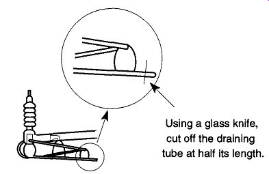
Fig. 25 How to drain the oil from a glass diffusion pump.
If you are removing a hydrocarbon oil, after the oil has sufficiently drained, use a cotton swab to clean any oil filling the drain tube. If you wish, pour a solvent through the pump to flush out the rest of the oil. You may want to temporarily plug the open end of the drainage tube with a cork to let the oil soak in the solvent.
Because the sharp ends of the (recently cut) tube will prevent the cork from obtaining a good seating, the broken end of the drainage tube should be fire-polished. Fire-polishing is likely to burn contamination into the glass, so leave room to remove this burnt end before extending the length of the tube.
Now, pour solvents or a base bath into the pump to soak the internal parts for about an hour or so.
If your pump used silicone oil and has left crusty remains that will not drain, a base bath is recommended (see Section 4.1.7). Place a cork in the end of the drainage tube (fire-polish as before), pour in a base bath solution, and let the pump sit for an hour or two. Because a base bath is highly flammable, be sure to unplug all electrical components of the pump before you begin this type of cleaning process.
After the base bath has been drained, let the pump soak for a few minutes with an acid rinse (to stop any alkaline reactions on the glass surface). After three or four water rinses, follow with a distilled water rinse and finally some methanol to speed the drying process. Do not blow air through the pump to speed the drying process as most compressed air is full of oils and other particulates (although dry nitrogen is acceptable). Alternatively, you can place the house vacuum hose to the pump and draw the ambient air through the pump. Remember, any acids or bases must be neutralized before disposal.
Hydrocarbon oils are generally easier to remove than silicon oils, but many of the hydrocarbon solvents used to remove these oils (such as chloroform) are considered by the EPA to be toxic. For seriously contaminated oils, and/or oils that are very tarry, something that is more heavy-duty such as decahydronaphthalene or trichloroethelene may be needed, but the latter is also considered to be a toxic waste. Each of these solutions should be followed by acetone and ethanol rinses.
Another diffusion pump oil, polyphenylether, can be dissolved in either trichloro-ethelene or 1,1,1-trichloroethane. Again, both of these are considered by the EPA to be toxic materials.
Be aware that the old oil from a pump (and any solvent used to clean out the old oil) more than likely contains any toxic materials that may have come from the vacuum system. For example, if the system had a McLeod gauge, it is likely that the old oil is contaminated with mercury. The amount of contamination concentration determines how the oil or solvent can be disposed of. Unfortunately, because of the possibility that specific EPA-established concentration levels will change before you read this guide, no disposal procedures are provided. Therefore, contact the EPA, or local regulatory agencies, to verify the various toxicity levels and the proper disposal procedures for materials of those levels.
If you are using a fluorinated oil such as fiuoropolyether, do not fire polish the end of the drainage tube and do not seal any glass onto the area until you have thoroughly cleaned the area. Any remaining grease that is heated higher than 280°C will turn into toxic fumes and could be lethal. You may use a fluorinated solvent such as trichlorotrifluoroethane or perfluorooctane to clean the system.
The biggest problem when using fluorinated materials (either as stopcock or joint grease or as pump oil) is the environmental hazard of the solvents needed for cleaning.
Instead of using the above solvents, most of which are (or will be) banned, one can use an industrial detergent, such as BH-38, to remove the fluorinated oils.
Simply by soaking the contaminated parts in the detergent can break up the oil for removal. There is no question that this will remove the vast majority of fluorinated solvent, but there is some question as to whether a film of the oil will remain.
Thus, severe heating (above 280°C) is still recommended against.
Several recommended procedures for working with solvents begins with using as little solvent as possible. In addition, many solvents can be reused. For example, a solvent used for a final rinse can later be reused for an earlier rinse on the next cleaning operation. After a solvent has been reused, it can be distilled, or roto-evaporated, so you end up with a smaller amount of contaminated liquid.
Because disposal costs are based on volume, any decreased amount of waste can provide significant cost savings.
After the cleaning has been completed, it may be necessary to remove the end of the drainage tube to remove any burnt deposit. Then, add an extension of the draining tube and close it off at about 1 to 1 1/2 in. (see Fig. 26). Now the pump can be refilled. The reason for cutting the drain tube in half (as mentioned) is to provide distance from the diffusion pump onto which you can fuse an extension.
If an extension were to be sealed directly onto the pump, extensive and formal annealing of the pump would be required.
The cleaning of a mercury diffusion pump* is somewhat simpler because mercury does not break down as most pump oils do. However, mercury gets dirty, and a dirty mercury pump still needs to be cleaned. After you have drained the mercury out of a glass diffusion pump, refill the pump with approximately a 6 molar nitric acid solution and let it sit until the mercury has been removed. Do not pour this liquid down the sink! Check with local waste management and/or your health and safety officer. The pump should be flushed with distilled water and then rinsed with methanol for drying.
To remove any mercury deposits from a metal vacuum pump, it is important to check with the manufacturer because some cleaning techniques may destroy the pump.
Alembics and distillation pots are not necessary on mercury diffusion pumps because mercury does not fractionate like oils. Although mercury and oil diffusion pumps use the same principle to function, they differ markedly in design. Because there is no fractionating ability in mercury pumps, oils cannot be used in mercury pumps. However, mercury can be used in an oil-designed metal pump on a limited basis-albeit with a noticeable loss of performance. Never use mercury in a diffusion pump with exposed heating elements because the mercury will short out the pump.
-------------
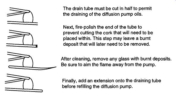
Fig. 26 The procedure for closing the drain tube on a glass diffusion
pump.
The drain tube must be cut in half to permit the draining of the diffusion pump oils.
Next, fire-polish the end of the tube to prevent cutting the cork that will need to be placed within. This step may leave a burnt deposit that will later need to be removed.
After cleaning, remove any glass with burnt deposits.
Be sure to aim the flame away from the pump.
Finally, add an extension onto the draining tube before refilling the diffusion pump.
--------------
3.18 Toepler Pumps
It is fairly easy to move condensable vapors from one section to another within a vacuum system by placing liquid nitrogen (within a Dewar) around a trap or sample tube. The condensable gas will travel to the trap, condense out, and/or freeze.
Non-condensable gases (helium and hydrogen for example) cannot be moved in this manner and require a Toepler pump.
Toepler pumps are used for the collection and transfer of non-condensable gases.
They are not capable of creating great vacuums, but they can be very effective pumps regardless. A 500-cm^3 size Toepler pump can remove 99.9% of a two-liter gas bulb in 10 minutes.
A Toepler pump is a piston pump with mercury as the piston. The mercury piston is powered by both the vacuum from a vacuum system and the atmosphere.
The actual operation of a Toepler pump involves evacuation followed by readmission of air out of, and into, the Toepler pump. There have been a wide variety of techniques to automate this process because manual operation can be quite tedious.
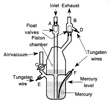
Fig. 27 General layout of a typical electrically operated Toepler pump.
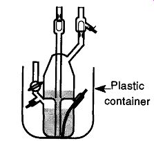
Fig. 28 By placing a Toepler pump (or any mercury-containing device) in
a plastic container, spills are avoided and it's protected from an accidental
bump.
The most common automation mechanism is to use the electrical conduction abilities of mercury to trigger switches that operate the pump. An example of such a Toepler can be seen in Fig. 27. In operation, the gas to be pumped enters the inlet at the top of the piston chamber. The pumping action begins when air is allowed into the lower chamber by the stopcock at C. The air forces the mercury up into the piston chamber and into the inlet and exhaust tubes. Finally, the mercury pushes up the float valves, preventing the mercury from going out the inlet.
Once the mercury makes contact with the tungsten wire at D, the circuit with the tungsten wire at F is complete. Then, the stopcock at C is rotated to evacuate the lower portion of the pump. The mercury finally is drawn back into the lower portion of the pump. The float valve at exhaust tube (at B) prevents gas being pumped from re-entering the Toepler pump. As the mercury fills the lower chamber, it fills the small chamber (with tungsten wire at E) which completes the circuit with the tungsten wire at F. This completion activates the stopcock at C to re-admit air into the pump, and the process repeats until it is manually turned off.
The major problem with this type of setup is when the mercury makes (and unmakes) contact with the tungsten wire at D. A spark may form that reacts with the gas being pumped through the exhaust. Mechanisms to by-pass this problem have included either placing the air/vacuum cycling on a timer, thereby bypassing the need of electrical contacts, or placing a photosensitive relay on the side of the exhaust tube, which is activated when the opaque mercury fills the transparent glass tube.
As with most items on a vacuum line that contain mercury, place the Toepler pump in a secondary container that is firmly attached to another surface to contain any mercury that may spill from an accident as well as protect the pump from accidental bumps (see Fig. 28). Plastic containers (such as plastic milk cartons) are particularly good because the mercury will not affect plastic. Conversely, mercury may amalgamate with the metals in a metal can, which could destroy any containment capabilities. In addition, it is easier to get mercury out of a plastic container (with smooth walls) than out of a metal one (with a narrow rim). The plastic tub can be glued onto the table with some epoxy. The epoxy will stick better if you roughen up the bottom surface of the plastic container with sandpaper.
Because not all epoxies stick to plastic, test the epoxy before assuming that it will hold.
Prev. | Next