AMAZON multi-meters discounts AMAZON oscilloscope discounts
(cont. from part 3 )
6.10 Helium Leak Detection
Imagine a room full of people. Now imagine you want to find the one(s) named Bill. If there was no way to easily identify the Bills, the process would become significantly laborious. However, if you called out and asked all those named Bill to please raise their hands, the task of identification becomes easy. The helium leak detector has the ability to isolate and count the helium atoms from a vacuum system full of many other atoms and molecules. In reality, the helium leak detector is nothing more than a customized mass spectrometer. The mass spectrometer was developed in the 1920s, but became a leak detection tool in the 1940s when the need for ultra-vacuum systems became critical on the Manhattan project.* The operation of a mass spectrometer is fairly straightforward. It places an electrical charge on all the gases passing through its system. This electrical charge allows a flowing path of charged gas molecules to be bent by a magnetic field. The angle of the bend depends on the mass of the molecule* and can be calculated with high precision. Because the particles have an electrical charge, they can be collected on a grid and counted. If a collection grid is placed at a specific point of the possible radius path, it is possible to collect only one type of molecule. A helium leak detector is a mass spectrometer that is permanently tuned to collect and record only the helium ion.
Without the magnet, the grid would collect all charged particles and the total gas pressure could be recorded. With the magnet separating the charged particles by their molecular weights, only helium is detected. This quality allows the helium leak detector a sensitivity of leak detection that is independent of total gas pressure. The leak detector will indicate that it is sensing helium by swinging a needle on a meter, sounding an electronic signal, and/or illuminating some type of display. For quantitative work, a digital or analog readout is required.
[* An interesting article on the development of the helium leak detector can be found in the article "History of Helium Leak Detection" by Albeit Nerken in the Journal of Vacuum Science, and Technology A, Volume 9, #3, pp. 2036-2038 (May/June 1991).
The more the magnetic field can bend the path, the smaller the radius and therefore the smaller the molecule.]
When helium leak detectors first became available, they were large and cumber some and required highly trained technicians. They were also very expensive.
Now, like most electronic equipment, they are smaller (relatively), easier to use (for some operations, they can be automated), less expensive, more reliable, more sensitive, and faster. As is typical of most things, helium leak detectors cannot have all the aforementioned attributes at once. However, it is possible to pick and choose which options are more important to you and select a detector that has features that are best suited to your needs. The usual tradeoff is sensitivity for speed.
Although there are other leak detectors and leak detection techniques that rely on detection of a change in gas, none have enjoyed the success of the mass spectrometer tuned to helium. There are other types of tuned mass spectrometers that specifically look for oxygen or halogen, but they are not as common. Their operation is similar to the helium leak detector, so the information here will also apply to them.
The use of helium as a probe (or tracer) gas in leak detection is not new. Before the mass spectrometer, it was used with thermocouple and/or Pirani gauges because of the greater thermal conductivity of helium than air. If you list all the attributes of a perfect probe gas, helium obviously does the job:
1. It should be nontoxic.
2. It should diffuse readily through minute leaks.
3. It should be inert.
4. It should be present in not more than trace quantities in the atmosphere.
5. It should be relatively inexpensive.
Helium is nontoxic and will not poison or affect living tissue. That is why it is safe to inhale helium and pretend you're a comedian.
The only danger that helium can present is that it can fill up a room, displacing oxygen so that there is an insufficient amount for human survival. However, because helium floats up and out of any room, this situation is extremely unlikely.
The evidence of helium diffusion through small leaks can be demonstrated by its ability to pass through glass. Everyone has seen how helium leaks out of a rubber balloon. Depending on the quality of the rubber, it can take anywhere from two to six hours of time to render a balloon into pathetic lethargy. The transfer of space-age plastics (Mylar) into balloon construction has added days to a toy bal loon's life because Mylar's molecules are more dense and it is more difficult for the helium atoms to diffuse past them. Borosilicate glass is more dense than rubber or Mylar and therefore does not leak as fast as either of them, but it leaks nonetheless. This fact has been successfully used for construction of "standard leaks" which are used to calibrate helium leak detectors (see page 458). [There is a type of glass called aluminosilicates (see page 14), which is helium leak-tight.] Only hydrogen (mass 1) has a smaller mass than helium (mass 4). Hydrogen can diffuse through materials very well, but it is dangerously flammable. Neon (mass 20) could be used, but it is much more expensive to use than helium. Argon (mass 40) is larger in size than the two main gases in the atmosphere [nitrogen (mass 28) and oxygen (mass 32)] and therefore would not be a good indicator of leakage potential of smaller materials.
[* From Introduction to Helium Mass Spectrometer Leak Defection by Varian Associates, Inc. ©1980, p. 21.
It is important for the comedian to occasionally take a breath of air to replenish some oxygen in his lungs or the joke will be on the comedian as he or she passes out.]
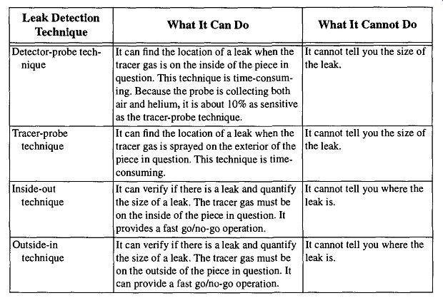
Table 17 Approaches to Helium Leak Detection
Being one of the noble gases, helium does not react with other materials. Its presence will not affect any of the materials of the vacuum system, nor will its presence affect any future work within the system. In addition, because it is a non condensable gas, it will not clog up any cold traps within the system or the detector during leak analysis. Helium, like other noble gases, is completely nonflammable.
Helium is found in extremely small quantities (approximately five parts per mil lion) in the atmosphere. Any discovery of concentrations greater than normal are easily discernible. Imagine the challenge of someone looking for water leaking out of a vessel held underwater.
Helium is relatively inexpensive.* Neon (mass 20), which could pass many of the qualifying tests for leak detection, fails here because of its greater costs.
Finally, it should be pointed out that helium leaks better than air because it is a much smaller molecule than air. The kinetic theory of gases predicts that helium will flow 2.7 times faster than air through an ideal leak at molecular flow conditions. Because of this property, helium can indicate a leakage rate that is greater than would be encountered in practice. For instance, because helium can permeate through O-rings, a helium leak detector could indicate a leak (albeit very small) at an O-ring joint despite the fact that oxygen or nitrogen are not likely to leak past the same O-ring.
[* This level of leak detection is not inexpensive: A new mass spectrometer helium leak detector with the accompanying equipment can easily cost between $20,000 and $30,000. Purchasing used equipment can significantly reduce the initial costs, but one should not enter the level of helium leak detection because it seems like a good idea. On the other hand, if you need a helium leak detector, you cannot afford not to have one.]
6.11 Helium Leak Detection Techniques
There are four different approaches to helium leak detection. They are displayed in Table 17. A graphical representation of these techniques is shown in Fig. 59 through Fig. 61.
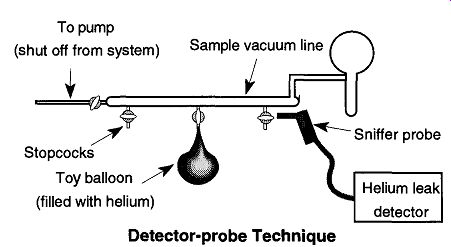
Fig. 59 In the detector-probe technique, the tested piece is filled with
helium and the sniffer probe "sniffs" the areas in question to
detect leaks. Always "sniff" from bottom to top.
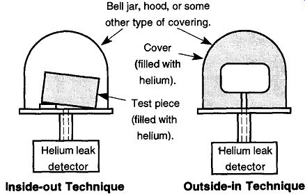
Fig. 60 Using the inside-out technique, the piece in question is filled
with helium and then placed in a covering of some type that can be evacuated.
Any helium that is released within this covering will be detected by the
helium leak detector. Note that the tested piece can have either end lifted
up so that all surfaces are exposed to the vacuum. From Introduction to Helium
Mass Spectrometer Leak Detection, Figs. 3.3 and 3.4, by Varian Associates,
Inc. © 1980. Fig. 61 With the outside-in technique,
the piece in question is directly connected to the helium leak detector.
A covering, or hood, is placed all around the tested piece and is filled with helium. Any helium escaping into the tested piece will be detected by the helium leak detector. From Introduction to Helium Mass Spectrometer Leak Detection, Figs. 3.3 and 3.4, by Varian Associates, Inc. © 1980.
Some of the other leak detection methods explained earlier in this section are based on these techniques. Methods such as bagging parts of a vacuum system and filling the bagged parts with a probe gas are similar to the outside-in technique. However, it is not possible to quantify a leak with this approach. Alternatively, filling a container with gas and either submerging it in a liquid or covering it with a bubbling solution is similar to the detector-probe technique.
What makes the helium leak detector unique is that it can be calibrated against a standard leak. Then, any measurements made (using the inside-out or outside-in techniques) can provide a quantifiable number. This calibration feature is usually more important to the manufacturing industry than to the needs and demands of the laboratory. For example, when the top of a soda pop can is scored to provide its "pop-top" feature, the depth of the scoring is very important: If the scoring is not deep enough, the top will not work as advertised; if it is too deep, the gases within the container can diffuse out, leaving a flat, nonbubbly product. So, by periodically checking to see that the amount of helium diffusion past the scored top is within tolerable limits, the canning industry can ensure that a good product will be delivered to customers, and the customers will be able to obtain access to the beverage. The canning industry does not care where the leak is-it already knows. What it does not know is if the leak is within tolerable limits or not.
When examining a vacuum system for leaks in the laboratory, calculating the size of a leak is often unnecessary for two reasons:
1. The techniques used to find the size of a leak entail the use of the inside out or outside-in techniques, both of which do not allow indication of where the leak is. With a vacuum system, we are trying to find the location of a leak so that the leak can be eliminated.
2. Although on occasion it may be useful to know the relative size of one leak to another, the specific size of a leak is irrelevant. If the leak is large in relation to the standard leak, it should be repaired. On the other hand, if the leak is close to the size of the standard leak (and your sys tem does not get below 10^-7 torr), there is little reason to repair the leak.
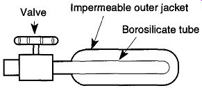
Fig. 62 An example of one standard leak design.
Even if there is no reason to quantify any given leak, it is still important to establish a leak limit for the helium leak detector before leak hunting begins. This limit is set with a standard leak.
A standard leak is a small container that leaks helium at a very slow and specific amount. As mentioned before, helium diffuses through borosilicate glass (or through ceramic or capillary tube). This diffusion is very consistent at any given pressure and temperature. Within the standard leak is a thimble of borosilicate glass (see Fig. 62) around which is the stored helium. The helium leak rate varies approximately ±3% per degree C above or below its standard temperature of 22°C.
Standard leaks come from the factory with their calibrated leak rate imprinted on their sides. The approximate annual attenuation is also indicated. After a certain amount of time (every 5 to 10 years) they can be returned to the factory for either recharging and/or recalibration. Recalibration is not critical if the helium leak detector is being used only for leak location and not leak calibration.
Standard leaks should be handled carefully and not dropped because sharp hits can break the glass inserts. They should not be stored with their valves closed.
Otherwise, an artificially high accumulation of helium would be created in the area between the valve and glass tube. The valve provides temporary stoppage of helium calibrations between its use during leak readings.
Because of the many different brands and types of helium leak detectors, it is impossible to explain how to operate your particular model use your owner's manual. If you cannot find the owner's manual for your machine, contact the manufacturer and obtain a replacement, possibly for a nominal charge. If you have been using your leak detector on the fly with apparent success, it would still be worth while to obtain the manual.
6.12 General Tips and Tricks of Helium Leak Detection
Probably the biggest problem with helium leak detector use comes from the construction material of the vacuum system or apparatus being tested. If the materials within the tested piece readily absorb helium, a false and/or confusing reading will exist for a considerable time afterward and will remain until the helium has left the piece.

Table 18 Permeability of Polymeric Materials to Various Gases
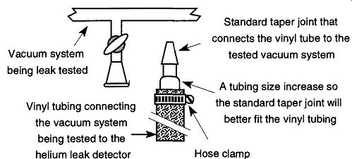
Fig. 63 Using standard taper joints to connect a helium leak detector
to the vacuum system being tested.
A second complication can come from materials that helium can easily permeate such as the elastomers used in O-ring connections. Helium readings from these materials can distract you from other "true" leak readings. Once an elastomer has become saturated with helium, it slowly desorbs the gas, which creates a large background noise. This background noise interferes with a helium leak detector's sensitivity and performance. All elastomers readily absorb, and slowly desorb, helium. Thus the fewer elastomers used within a system, the less of a problem there will be. Silicone tends to absorb helium the most, followed by natural rubber, Buna-N, and then neoprene. The permeability of several materials is included in Table 18.
One additional complication with elastomers has to do with the connection between a vacuum system and a helium leak detector. If it is possible, connect the two with a non-elastomeric connection such as a stainless steel bellows. If this connection is not possible, the best elastomeric connection that you can use is a high-vacuum, thick-walled (1/2 in I.D., 3/16 in. wall) vinyl tube of the shortest length possible. Do not use rubber or neoprene tubing. If you have several systems that may need leak detection, it is unlikely that one length of tube will accommodate all systems. It is best to have several connecting tubes, one for each system (or several systems) being tested, to allow you to select the shortest one that can be successfully used.
The actual connection between the vacuum system being tested and the helium leak detector can be made at a variety of points. One approach is to attach the connecting tube to the foreline of the diffusion pump where the fore pump would normally be connected. This attachment has the advantage of being physically at the end of the system, and therefore it is less likely to encounter confusing signals as you examine the system from one end to the other. The disadvantage is that you need to remove, and then later replace, the fore-pump hose. In addition, this attachment can only be made if the system being tested is small (i.e., less than 5 to 10 liters). If the system is any larger, the pumping system of the vacuum system being tested will be needed to assist the helium leak detector's pumping system.
Alternatively, you may attach the helium leak detector to any of the demount able connections that you already have on your system, such as standard taper joints (see Fig. 63). Always use a hose clamp on both ends of the tube connecting the helium leak detector and the vacuum system being tested to ensure a leak tight fit.
The simplest way to limit the effects of permeability during leak detection is to work quickly. The longer a material is exposed to helium, the greater the saturation will be, and the greater the amount of time necessary for the helium to be pumped out of the system. Helium can leak through an O-ring within five minutes, and even faster through a rubber diaphragm. If an O-ring becomes saturated with helium and its saturation is affecting your leak check, try removing the O ring and replacing it with one that was stored away from any helium. The offending O-ring will be fine to use again within several days. Another approach is to use the permeability of the helium in the elastomer as a base level, sort of a constant level of noise. Then all helium found beyond that level would indicate a leak.
Although this process eliminates the problem of changing elastomers, it significantly decreases the sensitivity of the leak detector.
Aside from permeability and absorbency complications, other universal concerns of helium leak detection are factors such as source operating pressure, spraying patterns (for tracer-probe technique), response time, clean-up time, and cold trap usage. Pump use and general helium leak detector maintenance operations are also fairly universal.
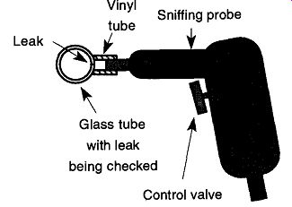
Fig. 64 Using a plastic tube to increase the sensitivity of a sniffing
probe.
The source operating pressure is the vacuum necessary to operate the leak detection device. This pressure is not specific, rather it is a pressure range within the leak detector which works. Optimistically, we want the helium leak detector, and the system to which it is connected, to have the greatest possible vacuum.
This gives the tracer-probe technique the maximum sensitivity with the quickest response time. As an added benefit, when one is operating at a very high vacuum, the amount of maintenance required for the leak detector is at a minimum due to less potential contamination. (There is, of course, an amusing contradiction here:
if you require a leak detector, you are not operating at the highest possible vacuum.) Most helium leak detectors will not operate with pressures above 10^4 torr to 10^5 torr. At these greater pressures, the main element to the mass spectrometer will burn out. Fortunately most, if not all, helium leak detectors have various safety check mechanisms that automatically shut off the current to the main filament if the pressure goes above a set limit. So, you must depend on alternate leak detection methods, or use the detector-probe technique to discover large leaks. Once large leaks have been discovered and closed, you can concentrate on the smaller leaks that can be found with the tracer-probe technique.
The detector-probe technique is, at best, about 10% as sensitive as the tracer probe technique. It can be made more sensitive by placing a greater pressure of the probe gas within the system. This greater pressure cannot be used on glass systems for fear of blowing out stopcock plugs or standard taper joint pieces. One technique for introducing helium to your vacuum system (with a moderate pres sure) is simply to fill a balloon with helium and attach it to the vacuum system.
The pressure within a helium balloon is not great enough to do any damage to a glass vacuum system. However, be careful how you "sniff around the balloon to avoid misreading helium permeating from the balloon walls. Using a Mylar bal loon will provide less permeation through the walls, but it is more difficult to attach to the vacuum system.
By placing a small vinyl tube over the end of the "sniffer probe" (see Fig. 64), it is possible to press the tip of the probe over the area of the possible leak. This method closes the leak off from ambient air, which both increases the sensitivity at this location and helps to precisely pinpoint the leak site. If you hold the vinyl tube too long near the helium, it will become saturated, and your "sniffer" will be reading the "leak" from the plastic on the nose of the probe. If this saturation occurs, have another plastic tube (that has been kept away from any helium) ready to slip on. A saturated tube will lose its helium in several days.
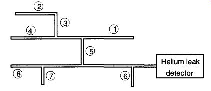
Fig. 65 A suggested pattern for spraying helium on a vacuum system when
using the tracer-probe technique. The pattern is a compromise between proximity
to the leak detector and spraying high before low areas.
If you ever wish to change from the detector-probe technique to the tracer-probe technique, you must remove all the helium already in the vacuum system by running the leak detector's vacuum system and/or the pumps of the vacuum system being tested for a period of time. Otherwise false and/or artificially high readings may affect any serious or useful leak testing. A dry nitrogen purge is recommended to help sweep the helium out of the system.
The spraying pattern used with the tracer-probe technique is important.
Improper spraying can significantly affect the amount of time and quality of the leak detection. If there is too much ambient helium in the air (caused by sloppy helium spraying), false readings can result. You can blow helium from a pipette tip or from a blunt hypodermic needle inserted in the end of a tube connected directly to a regulator on a helium compressed gas tank. To control the flow rate, you will need to adjust the needle valve on the regulator. To see the amount of helium spraying out of the tip, place the pipette tip into a beaker of water. The flow rate can then be set to allow for a slow but steady stream of bubbles.
The location of where to spray is a combination of (1) spraying the system parts close to the helium leak detector and then moving further out and (2) spraying the highest parts of the system and then moving on down toward the floor. The reason for the former is to keep cleanup time and response time to a minimum. Other wise, you must wait for all the helium to be removed before you can check for leaks closer to the detector. The reason for the latter is because helium rises in air.
If you spray down low first, the helium that drifts up may get sucked into an unknown leak in a higher section of the vacuum system, thus creating confusion as to whether the leak is in the area you are studying or anyplace above the area you are studying. See Fig. 65 for a suggested spraying pattern.
Response time can be easily explained with a hot water analogy: When you turn on the hot water in your shower, water immediately comes out of the shower fix ture, but there is a time lag before hot water arrives. This lag time is simply a function of water pressure, the amount you have the valve open, the pipe diameter, and the distance between the hot water tank and the shower. It is important to keep in mind this delay factor, or response time, when operating a helium leak detector.
For example, say your setup takes one minute from the time you introduce helium to a leak until it is acknowledged by the helium leak detector. In addition, say your spray probe is being moved at four inches per minute (which is pretty slow if you think about it). You will therefore be four inches away from a leak when it is first identified. Generally, moving the spray probe at a rate of one foot per minute pro vides an adequate time response, which of course can be made faster or slower as conditions warrant. However, if you know the response time, you will know about how much to back up to retest the area in question to allow pinpointing the specific leak spot.
The response time for a helium leak detector is "the time required for a known leak rate to be indicated on the leak detector from zero to 63% of its maximum equilibrium level." Of course the helium leak detector must be calibrated with a standard leak so that the maximum reading can be properly set on the leak detector. The response time is dependent on the quality of vacuum, the size of the leak, physical barriers (such as constrictions, bends, or traps) between the leak and the leak detector, and the proximity of the leak to the leak detector. Because of so many factors, there can be no set specific response time.
The cleanup time is the length of time for the detection signal to stop indicating that it is sensing a leak. More specifically, it is "the time required after removal of a tracer gas from a leak for the initial leak indication to decay 63% of the indication at the time the leak was removed." 88 Cleanup time is almost always longer than response time because of the difficulty in desorption of helium from a vacuum system, compounded by helium permeation into porous materials. So, when using the tracer-probe technique do not overspray helium onto your system. The more helium that enters your system, the more that can permeate into porous materials and the longer the cleanup time.
Liquid-nitrogen cold traps stop condensable vapors* from traveling between mechanical pumps, diffusion pumps, and the rest of the system. They also protect the helium leak detector from possibly contaminating materials (such as silicon based diffusion pump oil).
Any coating that develops on the ion source of the helium leak detector will hinder operation. This coating is not easy to prevent because during operation, the ion source behaves like a getter-ion pump, drawing materials to its surface. There fore anything that can be done to protect the ion source without hindering normal operation is desirable.
During operation, maintain the liquid nitrogen at a constant level to prevent the evaporation of condensable vapors that could in turn collect on the ion source.
Use the trap-filling method suggested in Section 4.3.
[ Helium is a non-condensable gas. If you are using an oxygen or halogen probe gas, you have a new complication because these gases are condensable. Thus, using a cold trap will likely prevent the leak detector from detecting the tracer gas. Because a liquid nitrogen cold trap would not be practical in this circumstance, consult the manufacturer for assistance on how to protect the electronics of your leak detector.]
During operation, if a heavy buildup of vapors collects on the cold trap, an incidental backlog of probe gas can develop, thus causing a rise of background probe gas noise, which in turn slows down the speed of detection ability and decreases the sensitivity of the leak detector. If this situation develops, close the valves to the vacuum system being checked, turn off all gauges within the leak detector,* and let the cold trap heat up. Meanwhile, the pumps should remain on to draw the condensable vapors from the leak detector. Do not run the mechanical pump with the diffusion pump off under a no-gas load (nothing coming in) condition because mechanical pump oils will backstream into the diffusion pump.
[ This procedure should always be done when running any vacuum system without the use of traps because of the damage some condensable vapors can do to vacuum gauges.
On a regular vacuum system, this can be done by either (a) separating the diffusion pump from the rest of the system by stopcocks or valves or (b) the use of a nitrogen cold-trap between the mechanical and diffusion pump.]
The following are several extra general maintenance tips:
1. If you need (or desire) to run the mechanical pump of a helium leak detector with the diffusion pump off, the best means to protect the diffusion pump oils is with a dry nitrogen gas purge. This purge will prevent mechanical pump oils from backstreaming into the diffusion pump.
The leaking dry nitrogen maintains a low-level laminar flow toward the mechanical pump. The nitrogen (leak) pressure should be maintained between approximately 1 and 10^-2 torr.
2. Never use anything but hydrocarbon oils in the diffusion pumps of helium leak detectors. Silicon oils can deposit insulating layers on the ion sources of the mass spectrometers and ion gauges. However, if hydrocarbon oils are allowed to migrate to the guts of the leak detector's mass spectrometer section, they can be cracked by ions and electrons. The cracked hydrocarbon remains can deposit on the filaments and other system parts, causing a loss of sensitivity and resolution.
Admittedly the effects of hydrocarbons are not good, but they are better than the effects of silicon oils.
3. Within a helium leak detector, there are valves that isolate the mass spectrometer and gauge sections, the diffusion pump, and the trap from the rest of the system. These valves are used to prevent contamination or damage to these sections when cleaning, adjusting, or venting is required during use. Find and use them.
4. When shutting down a system, it is best to remove a cold trap while it is still full of liquid nitrogen. This removal procedure will help decrease the amount of material that could pass into the leak detector, or the leak detector's pumping system, after the system is turned off. The process for removing a trap is as follows:
(a) Be sure that all protective valves around the cold trap are closed before venting the area around the trap to atmospheric pres sure.
(b) Wear protective gloves.
(c) Pour the liquid nitrogen into another Dewar, or some safe receptacle. Do not pour the liquid nitrogen down a sink or in a container not designed to hold cryogenic materials.
(d) Allow the trap to warm up.
(e) Gently wipe clean with a rag or Kimwipe. Use tolulene for a final wipe (these traps are made of very thin metal to facilitate heat transfer. They are very vulnerable to dings, bangs, and bumps, so be very careful).
(f) When replacing a trap, be sure that any gasket (if present) is clean and in place. If there are any bolts to tighten, use a rotational tightening pattern as shown in Fig. 53.
Alternatively, you can run a dry nitrogen gas purge at a pressure of approximately 200-3000). This purge should be left on after the diffusion pump is turned off, and it should remain on while the mechanical pump is left to pump overnight.
As the trap warms up, all the contaminants will be discharged out of the system.
The next day, the leak detector can be restarted by adding liquid nitrogen to the trap, starting the diffusion pump, and turning off the nitrogen purge.
Calibration can be done every time you start a system up; but for general leak detection, calibration is less important. However, whenever any general repair or replacement maintenance is performed, such as replacing the filament on a mass spectrometer, calibration becomes mandatory. See your owner's manual for specific instructions.
The repair of a leak on a glass system should be done by someone with glassblowing experience.]
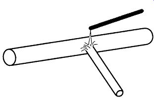
Fig. 66 Removing a hole from a glass seal by removing the glass around
the hole with a glass rod and a gas-oxygen torch (not shown).
6.13 Repairing Leaks
If a leak has been located with a Tesla coil, you may find a (very) small white dot where the spark went through the glass. This dot may be hard to relocate, so it is best to clearly mark the exact location of the hole with a grease pencil or any other marker that can write on glass. Other leak detection techniques do not leave any mark, and some marking is essential.
The best possible repair for a leak within a glass system* is for the leak to be removed (see Fig. 66), the whole area to be heated and blown smooth, and, finally, the worked area to be flame-annealed to prevent later cracking.
A temporary solution to vacuum system leaks that has been used for quite some time is the application of Glyptol. Although this approach may work in some isolated circumstances, covering a hole with Glyptol or any other temporary patch should not be relied on because:
1. There is a chance that you may create a virtual leak.
2. Once a system is (temporarily) repaired, there is a good chance that the need for a permanent repair will drop ("out of sight, out of mind").
Temporary repairs are, at best, temporary and should not be relied on for future needs.
3. Glyptol, or other temporary leak repair material, can be very difficult to properly remove from a glass surface. Total removal of any temporary sealant must be done before any glassworking can be done.
Obviously there will be times when the temporary repair of a leak is essential, but otherwise it is best to make all repairs permanent.
After a leak has been discovered and removed and the glass repaired, flame annealed, and cooled, the system must be leak checked again not only to verify that the repair was successful, but to see if there are any other leaks that need repair. It is not uncommon for another leak to be immediately adjacent to the first leak. An adjacent, smaller may be unable to attract the spark from a Tesla coil away from a larger leak. Or, a larger leak can cause too much helium noise for a smaller leak to be pinpointed. However, once larger leaks are repaired, smaller leaks can be more readily identified.
7. More Vacuum System Information
7.1 The Designs of Things
As you work with vacuum systems, you may be called upon to design new parts and/or sections for the system. Your success will depend on your experience with the materials you select, your choice of materials, and your access to experienced technicians.
If you require metal components on your vacuum system, select metals with low gas permeation, such as 300 series stainless steel. It is nonmagnetic and, like glass, is a poor conductor of heat and electricity. Stainless steel, also like glass, is relatively nonreactive, and therefore is less likely to rust or be affected by chemicals. If welding the stainless steel is required, select 304L stainless steel, which is low in carbon. Otherwise, at welding temperatures the carbon will combine with the chromium (within the stainless steel) to form chromium carbide and the corrosion protection of the chromium will be lost. Type 303 stainless steel should not be used for vacuum work because it contains selenium, which has a high vapor pressure.
The metals zinc and cadmium should be avoided because of their high vapor pressures. Metals that include zinc and cadmium alloys such as brass (copper and zinc) and some silver solders (cadmium) should also be avoided for the same reasons. It is possible to obtain cadmium-free silver solder and brazing materials that use tin, lead, and indium for vacuum use. Some steel screws are cadmium-coated and also must be avoided.
Copper is often used as gasket material, such as in Conftat (Varian) flanges, however, standard copper is often permeated with oxygen. If copper is heated in a hydrogen environment, the oxygen combines with the hydrogen to form water, which causes the copper to become brittle. Thus, when selecting copper, obtain OFHC (oxygen-free high-conductivity) copper.
Besides copper, indium is often used as a metal gasket material. Despite its lack of elasticity and its limited operating temperature (100°C), indium wire (0.8 - 1.6 mm) can easily be bent into a circle of any desired size and, if the ends are over lapped, no soldering is required. Aluminum can be made into a gasket as well by using a wire (0.5 - 1 mm), bending it into a circle of the desired size, and soldering it together using a flux. The flux must be washed off before use. Aluminum can be used to temperatures as high as 400°C. Gold is probably the best material for gaskets because it requires no flux to join the ends of a circled wire and can be used to temperatures as high as 450-500°C.
Parts are fairly easy to attach and change with metal systems; it is mostly a matter of unbolting one unit and replacing it with another. Be sure to follow the bolting techniques described in Section 6.4 to ensure even cutting on gaskets and equal torque on flange surfaces.
Glass systems are a little different: If you have not worked with glass before, do not try to learn glassblowing on an already made vacuum system. If you want to learn some glassblowing techniques, it is imperative that you start with small items at a bench before risking the destruction of a very valuable piece of equipment. Watching an experienced glassblower is deceiving because it looks easy. A concert pianist makes playing piano look just as easy, but playing the piano is just as difficult.
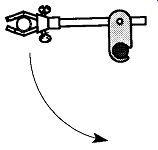
Fig. 67 Support on vacuum lines must be connected to the vertical bars
of a support rack, not the horizontal bars.
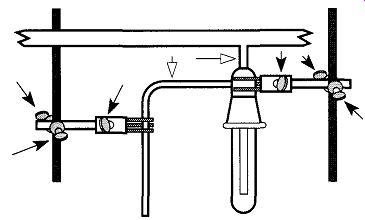
Fig. 68 I f you tighten two- or three-fingered clamps or clamp supports
(dark arrows), it is important to relieve the stress that is created on the
glass by heating the connecting glass (hollow arrows).
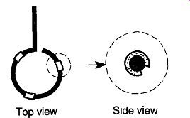
Fig. 69 Placing cut rubber tubing on a support ring makes a good support
for a round-bottom flask.
This guide is not an instruction book on glassblowing. section 8 has some tips on gas-oxygen torch use, and Appendix D contains some recommended books for your consideration. The following discussion will also provide some of the dynamics of glass vacuum systems so that common errors and problems can be avoided. Consider the following questions before doing any glasswork and/or additions to a vacuum line:
Are the Glasses You Have to Work with Compatible ? Trying to repair a small leak in a vacuum line made of borosilicate glass by filling a hole with a soda-lime glass will result in an entire day of repair by a qualified person instead of the half-hour originally required.
Do Any of the Items Being Added onto the Vacuum System
Have any Concave Surfaces? Convex items can support themselves against atmospheric forces with a vacuum on the other side. Concave-shaped items, on the other hand, cannot deal with the stress unless they have been specially built. For example, a standard Erlenmeyer flask cannot withstand atmospheric forces against a vacuum because the base is somewhat concave. However, a filter flask can withstand these pressures because it is constructed out of heavy-walled glass. There should be the same concern of implosion, whether a vacuum is created by a small single-stage vacuum pump or with a vacuum system capable of ultrahigh vacuum. The greatest percentage of change in force against an walls of a container occur when the item is brought from atmospheric to about 1 torr because the primary force at work is atmospheric pressure, not the vacuum. Remember, a vacuum of about 1 torr can pull water about 33 ft into the air, but no matter how much more vacuum is applied, the height of the water is raised a millimeter or so.
Are Your Vacuum Line Supports on Vertical or Horizontal Rods of the Vacuum Rack? Vacuum lines are supported by two- and/or three-fingered clamps, which in turn are held onto the vacuum rack by clamp supports that grip the rack by screws. Regardless of how tightly a clamp support is screwed down, it's not difficult to swing a support one way or another. This movement can be an advantage if you wish to swing away a support for a Dewar, but could be a disaster for a vertical axis support of a vacuum line (see Fig. 67). A disaster could also happen when an entire system or just a single item, is supported on horizontal bars.
Are Sections Between Vacuum Parts Breaking as You Tighten Two- and/or Three-Fingered Clamps or Clamp Supports? Glass is perfectly elastic until the point of fracture and it is easy to place too much torque against glass with the tightening screws of clamp fingers and/or clamp supports. During and/or after placing parts of a vacuum system in these devices, relieve the tension by heating the glass sections between the clamps (see Fig. 68). The heating should be done with a gentle, bushy flame. Be careful not to get the flame near larger-diameter tubing or near glass seals that could cause strain within the glass. These situations could cause later cracks or breaks.
Are There Rubber Cushions Supporting Round-Bottom Flasks on Support Rings? By simply taking pieces of rubber tubing and slitting them open along one side, protective surfaces are made on which to lay round-bottom flasks (see Fig. 69). This method of protection should not be used if a round-bottom flask is wanned greater than 100°C, or if you plan to heat the round-bottom flask in its support (see Section 1.1.9 for information on how to heat round bottom flasks). Such heating can burn or melt the rubber or vinyl tubing, releasing dangerous fumes.
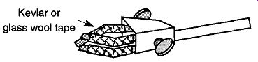
Fig. 70 Use Kevlar or glass wool tape on two- and three-fingered clamps,
especially if they will be subjected to any heat.
Is There Fiberglass, Kevlar, or Ceramic Tape Protecting the Glass from Two- or Three-fingered Clamp Arms? When purchasing new two- or three-fingered clamps, they will be supplied with either a plastic coating or fiberglass covers on the fingers. Asbestos covers are no longer commercially available. The plastic provides protection for the glass, but cannot survive any significant heat or direct flames. It is possible to obtain fiberglass covers to replace the coverings on older two- and three-fingered clamps (see Fig. 70). Another choice for covering clamp fingers is Kevlar tubing. The advantage of Kevlar is that one size of tubing will fit many size fingers. The drawback is that Kevlar tubing unravels easy, so it should be limited to long-term holding and not used with clamps that are in constant (open and close) use. There are dipping solutions sold in hardware stores whereby you can provide your tool handles a plastic covering. These products can be used to place, or replace, the plastic on clamp fingers. Two to three coats have shown to provide an excellent coating. Be sure to use with adequate ventilation as they typically contain tolulene.
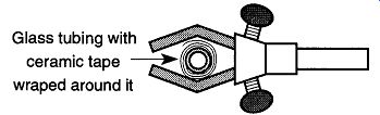
Fig. 71 Wrapping ceramic tape around glass tubing makes it easier to be
held by two- or three-fingered clamps.
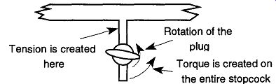
Fig. 72 By rotating the stopcock plug without proper support, torque is
created on the stopcock. If the tension is great enough, the stopcock may
break.
Are You Unable to Squeeze the Fingers of a Two-Fingered Clamp Down Sufficiently to Obtain a Good Grip on Small-Diameter Tubing?
There are two choices to resolve this problem depending on the conditions surrounding the section of tubing in question. The easiest solution is to take a short piece of flexible tubing, slit open the side, and wrap this tubing piece around the glass tubing where the clamp will support the item. This slitting of the flexible tube is exactly the same process described in Fig. 69, except the slitted tube goes onto straight tubing instead of the support ring. If, on the other hand, the glass tubing will be heated, the piece of flexible tubing could be damaged. In these environments, wrap ceramic tape* (do not use asbestos tape) around the tubing that would other wise be too narrow for a fingered clamp to obtain a firm grip (see Fig. 71).
Are You Snapping Stopcocks Off at the Base While Rotating the Plug? Whenever possible, stopcocks should be supported from both ends by fusion to other glass and/or by a two- or three-fingered clamp, although this support cannot always be supplied. One of the purposes of an extra clamp is to provide support and bracing against the torque from accidental knocks. The main purpose of an extra stopcock is to protect it from heavy-handed rotation. As stopcock grease gets old, it becomes thicker and loses its slippery nature. When rotating a stopcock plug with old grease, tremendous torque can be created on the stopcock and it can snap off at the base (see Fig. 72).
This breakage can be prevented by maintaining fresh stopcock grease in the stopcock and by holding the stopcock with one hand while rotating the plug with the other. In fact, it is always best to hold the body of a stopcock with one hand while rotating the plug with the other.
References
1. H.G. Tompkins, An Introduction to the Fundamentals of Vacuum Technology, American Vacuum Society, American Institute of Physics, New York, 1984, p. 2.
2. R.J. Naumann, "Prospects for a Contamination-Free Ultravacuum Facility in Low Earth Orbit," Journal of Vacuum Science and Technology 7, 90-99 (1989).
3. J.F. O'Hanlon, A User's Guide to Vacuum Technology, Wiley-Interscience, John Wiley & Sons, New York, 1980, p. 11.
4. A. Guthrie, Vacuum Technology, Wiley-Interscience: John Wiley & Son, New York, 1963, p. 6.
5. T.E. Madey, "Early Applications of Vacuum, from Aristotle to Langmuir," Journal Vacuum Science and Technology, A, 2,110-117 (1984).
6. M.H. Hablanian, and B.B. Dayton, "Comments on the History of Vacuum Pumps," Journal Vacuum Science and Technology A, 2, 118-125 (1984).
7. J.H. Singleton, "The Development of Valves, Connectors and Traps for Vacuum Systems During the 20th Century," Journal Vacuum Science and Technology, A, 2, 126-131 (1984).
8. P.A. Redhead, "The Measurement of Vacuum Pressures," Journal Vacuum Science and Technology, A, 2, 132-138 (1984).
9. J.F. Peterson, "Vacuum Pump Technology; A Short Course on Theory and Opera tions, Part I," Solid State Technology, 24, 83-86 (1981).
10. R. Barbour, Glassblowing for Laboratory Technicians, Pergamon Press., Pergamon Press, Elmsford, NY, 1978, pp. 184-186.
11. A.M. Russel, "Use of Water Aspirator in Conjunction with Sorption Pumping on an Ultrahigh Vacuum System," Review of Scientific Instruments, 36, 854 (1965).
12. P. Sadler, "Comparative Performance Characteristics Between a Vane and a Rotary Piston Type of Mechanical Vacuum Pump," Vacuum, 19, 17-22 (1969).
13. M.H. Hablanian, "Performance of Mechanical Vacuum Pumps in the Molecular Flow Range," Journal Vacuum Science and Technology, A, 19, 250-252 (1981).
14. Welch Vacuum Technology, Inc., 1988, p. 125.
15. Z.C. Dobrowolski, "Mechanical Pumps," in Methods of Experimental Physics, Vol. 14, G.L. Weissler and R.W. Carlson , eds., Academic Press, New York, 1979, pp. 468-471.
16. N. Harris, Modern Vacuum Practice, McGraw-Hill, Berkshire England, 1989, pp. 78-80.
17. C.J. Carstens, C.A. Hord, and D.H. Martin, "Mercury Contamination Associated with McLeod Gauge Vacuum Pumps," Review of Scientific Instruments, 36, 1385-1386(1972).
18. M.H. Hablanian, "Comments on the History of Vacuum Pumps," Journal Vacuum Science and Technology, A, 2, 174-181 (1984).
19. J.F. O'Hanlon, A User's Guide to Vacuum Technology Wiley-Interscience, John Wiley & Sons, New York, 1980, p. 165.
20. M.H. Hablanian, "Mechanical Vacuum Pumps," Journal Vacuum Science and Technology, A, 19, 250-252 (1981).
21. W. Strattman, "Foreline Traps," Signs of the Times, 218, 34-38 (1996).
22. Shriver, DF, & Drezdzon, MA, The Manipulation of Air-Sensitive Compound, Wiley-Interscience, John Wiley & Sons, New York, 1986, pp. 7-8.
23. Ibid.Ref. 22, p. 31.
24. R. Rondeau, "Design and Construction of Glass Vacuum Systems," Journal of Chemical Education, 42, A445-A459 (1965).
25. W. Strattman, Signs of the Times, February, 219, 48-64 (1997).
26. Ibid, Ref. 25.
27. M. Wheeler, "4" Glass Oil Diffusion Pump," Proceedings of the American Scientific Glassblowers Society Proceedings, 40th, 24-30 (1995).
28. N.S. Harris, "Practical Aspects of Constructing, Operating, and Maintaining Rotary Vane and Diffusion-Pumped Systems," Vacuum, 31, 173-182 (1981).
29. J.F. Peterson and H.A. Steinherz, "Vacuum Pump Technology; A Short Course on Theory and Operations, Part I," Solid State Technology, 24, 83-86 (1981).
30. G.F. Weston, "Pumps for Ultra-high Vacuum," Vacuum, 28, 209-233 (1978).
31. Ibid, Ref. 30.
32. L. Laurenson, "Vacuum Fluids," Vacuum, 30, 275-281 (1980).
33. J.F. O'Hanlon, A User's Guide to Vacuum Technology Wiley-Interscience, John Wiley & Sons, New York, 1980, p. 198.
34. Ibid, Ref. 33.
35. D.J. Santeler, "Use of Diffusion Pumps for Obtaining Ultraclean Vacuum Environments," Journal of Vacuum Science and Technology, 8, 299-307 (1971).
36. W.W. Roepke and K.G. Pung, "Inexpensive Oil Vapor Trap for Use with Rotary Vacuum Pumps," Vacuum, 18, 457-458 (1968).
37. Ibid, Ref. 21.
38. S. Dushman, J.M. Lafferty, Ed., Scientific Foundations of Vacuum Technique, John Wiley & Sons, New York, 1962, pp. 204-205.
39. F. Rosebury, Handbook of Electron Tube and Vacuum Techniques, American Institute of Physics, New York, 1993 (originally published in 1964), p. 212.
40. Brown, A.B., Proceedings of the American Scientific Glassblowers Society Proceedings, 30th, 80-82 (1985).
41. W Jitschin, "Accuracy of Vacuum Gauges," Journal Vacuum Science and Technology, A, 8, pp. 948-956 (1990).
42. International Vocabulary of Basic and General Terms in Metrology, ISO, Geneva, 1984.
43. P. Nash, "The Use of Hot Filament Ionization Gauges," Vacuum, 37, 643-649 (1987).
44. W. Jitschin, "Accuracy of Vacuum Gauges," Journal Vacuum Science and Technology, A, 8,948-956 (1990).
45. Ibid, Ref. 28, pp. 173-182.
46. S.T. Zenchelsky, "Pressure Measurement, Part One," Journal of Chemical Educa tion, 40, A611-A632 (1963).
47. H.F. Carroll, "Avoid Parallax Error When Reading a Mercury Manometer," Journal of Chemical Education, 44, 763 (1967).
48. W.G. Brombacher, D.J. Johnson, and J.L. Cross, "Errors in Mercury Barometers and Manometers," Instruments & Control Systems, 35, 121-122 (1962).
49. S.O. Colgate and PA. Genre, "On Elimination of the Mercury Pumping Error Effect in McLeod Gauges," Vacuum, 18, 553-558 (1968).
50. J.K.N. Sharma et al., "A Simple Graphical Method of Pressure Determination in a McLeod Gauge," Vacuum, 31, 195-197 (1981).
51. K.B. Wear, "Condensable Gases in a McLeod Gauge," Review of Scientific Instruments, 39, 245-250 (1968).
52. C.J. Carstens, C.A. Hord, and D.H. Martin, "Mercury Contamination Associated with McLeod Gauge Vacuum Pumps," Review of Scientific Instruments, 43, 1385-1386(1972).
53. W. Jitschin, "Accuracy of Vacuum Gauges," Journal Vacuum Science and Technology, A, 8, 948-956 (1990).
54. J.C. Snaith, "Vacuum Measurement," Journal of the British Society of Scientific Glassblowers, 7, 3-7 (1969).
55. R.N. Peacock, N.T. Peacock, and D.S. Hauschulz, "Comparison of Hot Cathode and Cold Cathode Ionization Gauges," Journal Vacuum Science and Technology, A, 9, pp. 1977-1985 (1991).
56. W.B. Nottingham, 7th Ann. Conf. on Phys. Electron., M.I.T. (1947).
57. K.E. McCulloh and R. Tilford, "Nitrogen Sensitivities of a Sample of Commercial Hot Cathode Ionization Gas Tubes," Journal Vacuum Science and Technology, A, 18,994-996(1981).
58. M. Hirata, M. Ono, H. Hojo, and K. Nakayama, "Calibration of Secondary Standard Ionization Gauges," Journal Vacuum Science and Technology, A, 20, 1159-1162 (1982).
59. H.C. Hseuh, "The Effect of Magnetic Fields on the Performance of Bayard-Alpert Gauges," Journal Vacuum Science and Technology, A, 20,237-240 (1982).
60. N.S. Harris, "Practical Aspects of Constructing, Operating, and Maintaining Rotary Vane and Diffusion-Pumped Systems," Vacuum, 31, 173-182 (1981).
61. Ibid, Ref. 60.
62. R.N. Peacock, N.T. Peacock, and D.S. Hauschulz, "Comparison of Hot Cathode and Cold Cathode Ionization Gauges," Journal Vacuum Science and Technology, A, 9, 1977-1985 (1991).
63. N.S. Harris, "Practical Aspects of Constructing, Operating, and Maintaining Rotary Vane and Diffusion-Pumped Systems," Vacuum, 31, 173-182 (1981).
64. JJ. Sullivan, " Research Efforts Boost Range and Accuracy of Vacuum Gages," Industrial Res. & Dev., 25, 161-169 (1983).
65. H.A. Tasman et al., "Vacuum Techniques in Conjunction with Mass Spectrometry," Vacuum, 15, 33 (1963).
66. Ibid, Ref. 65.
67. D.F. Klemperer, "Recent Developments in Ultrahigh Vacuum," Journal of the British Society of Scientific Glassblowers, 2, 28-38 (1965).
68. Tom Orr, personal conversation.
69. A.H. Turnbull, "Leak Detection and Detectors," Vacuum, 15, 3-11 (1965).
70. Dr. Cathy Cobb, personal conversation.
71. D. Santeler, "Leak Detection-Common Problems and Their Solutions," Journal Vacuum Science and Technology, A, 2, 1149-1156 (1984).
72. A.H. Turnbull, "Leak Detection and Detectors," Vacuum, 15, 3-11 (1965).
73. W. Fiszdon, " 'Ad Hoc' Liquid Spray Vacuum Leak Detection Method," Physics of Fluids, 22, 1829-1831 (1979).
74. Ibid, Ref. 73.
75. G. Coyne and C. Cobb, "Efficient, Inexpensive, and Useful Techniques for Low Vacuum Leak Detection with a Tesla Coil," Journal of Chemical Education, 68, 526-528 (1991).
76. A. Guthrie, Vacuum Technology, John Wiley & Sons, New York, 1965, p. 514.
77. L.H. Martin and R.D. Hill, Manual of Vacuum Practice, Melbourne University Press, Melbourne, 1946, p. 112.
78. Ibid, Ref. 76, p. 514.
79. E.L. Wheeler, Scientific Glassblowing, Interscience Publishers, New York, 1958, p. 348.
80. W. Espe, Materials for High Vacuum Technology, Vol. 3, Pergamon Press, New York, 1968, p. 393.
81. J.F. O'Hanlon, A User's Guide to Vacuum Technology, John Wiley & Sons New York, 1980, p. 365.
82. Ibid, Ref. 71, pp. 1149-1156.
83. Ibid, Ref. 76, p. 468.
84. C.C. Minter, "Vacuum Leak Testing with Liquids," Rev. Sci. Inst., 31, 458-459 (1960).
85. Varian Associates, Inc. Introduction to Helium Mass Spectrometer Leak Detection, published by Varian Associates, Inc. ©1980.
86. N.G. Wilson, and L.C. Beavis, Handbook of Vacuum Leak Detection, published by the American Institute of Physics, Inc., © 1976, 1979, p. 26.
87. Ibid, Ref. 86, p. 37.
88. Ibid, Ref. 86 pp. 39.
89. Ibid, Ref. 71, pp. 1149-1156.
Prev. | Next