AMAZON multi-meters discounts AMAZON oscilloscope discounts
(cont. from part 2 )
6. Leak Detection and Location
6.1 All About Leaks
There are seven sources of leaks in vacuum systems. All of these leak sources can make the job of maintaining a vacuum more difficult than obtaining a vacuum. An illustration of these unwanted gas sources within a vacuum system can be seen in Fig. 50. Perhaps one of the most subtle sources of leaks into an ultrahigh-vacuum system is permeation of the glass by helium, present in the atmosphere at 5.24 ppm (see Table 3). Helium permeation* of glass can be useful for a standard leak (used with a He leak detector, see Secs. 6.10 - 6.12), but can be debilitating when trying to obtain extremely ultrahigh vacuum with glass components. This can essentially eliminated if aluminosilicate glass is used in the construction in the region where such is not desired. For more information on aluminosilicate glass.
Evaporation (outgassing) is the release of adsorbed molecules at room tempera ture and pressure, while desorption (degassing) is the forced evaporation of molecules by either applying greater heat or decreasing the ambient pressure.
Diffusion is the movement of atoms or molecules through solids, liquids, or gases. The rate of transport is always governed both by concentration variations in the material and by the size ratio of the diffusing material and the material it's passing through. Once the material has diffused to the surface, it can be desorbed into the system.
[Permeation (and absorption) are both conditions that only apply when the penetrating molecule is much smaller than the molecules of the wall material. A molecule of any size can be involved in adsorption.]
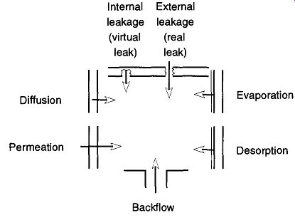
Fig. 50 Gas sources in a vacuum system. From An
Elementary Introduction to Vacuum Technique, G. Lewin, Fig. 19, ©1987 by The American Vacuum Society,
American Institute of Physics, New York, reprinted (abstracted) with permission.
Permeation is a three part process. The material is first absorbed into the material it is about to pass through. Then, the contaminant diffuses through the material. Finally, the contaminant desorbs into the system.
The second gas law states that there cannot be unequally distributed partial pressures in any system. Thus, the greater the vacuum, the greater the rate of desorption, diffusion, and permeation to overcome the differences in concentration as "nature abhorring a vacuum" tries to equalize the system.
Backflow (also called back diffusion or back migration) occurs when the pressures at the outlet and inlet have established a constant ratio (this is analogous to the compression ratio found in mechanical pumps). At that point, gases can drift either way in the vacuum system. Proper trapping or baffling is an easy mechanism to prevent this problem.
False (virtual) leaks are discussed in Section 6.3 and external (real) leaks are discussed in Section 6.4.
Water adsorbs into the walls of a glass container, but that adsorption is the extent of its adhesion. Some adsorbed molecules react chemically with some types of containers in a process called chemical adsorption (chemisorption. For example, carbon monoxide chemisorbs with palladium, but not with gold). The bonds resulting from chemisorption can hold molecules to the surface with far greater force than would exist with only physical attraction. It is also possible for a molecule (that normally would not chemisorb with the container wall) to break up when hitting the wall's surface. At that point the molecule's constituent parts chemisorb with the container walls. When an adsorbed gas reacts with the materials of a container, it is called reconstruction (for example, the reconstruction of iron with oxygen is rust).
6.2 Is Poor Vacuum a Leak or a Poor Vacuum?
Looking for a leak is only fruitful when you know there is a leak. Just because you have a poor vacuum does not mean that you have a leak. In the art and science of leak detection, you must first verify whether a problem really exists before you try to do something about the (perceived) problem. Only after you have established that there is a problem can you begin to locate the source of the problem.
It is impossible to obtain a perfect vacuum; there is no way to remove all molecules from a given area. With that idea in mind, the best vacuum of any vacuum system is limited by the quality and design of your vacuum pumps, the composition of material in your vacuum system, and the design of your vacuum system.
Ultimately, a leak-tight vacuum system* will be limited by leaks from the outgas sing of materials from your system, diffusion of gases from the walls, permeation through the walls, evaporation and desorption from wall surfaces, and backflow from the pumping systems.
Because no vacuum system can be truly leak-free, it is important to determine whether or not you have a leak of consequence. In other words, does any system leak actively affect your work? For example, a common rubber balloon holds water better than it holds air, and it holds air better than it holds helium. If your needs are to contain water, a standard rubber balloon is sufficient. Similarly, if you want to contain helium for a limited time, again a rubber balloon is sufficient.
However, if you want a helium balloon to stay up for several days, then a rubber balloon is insufficient and you must spend the money for a Mylar balloon, which can contain helium much better than a rubber balloon.
In addition to knowing the intended use for a vacuum line, you also need to know its history. By knowing the vacuum line's history, you can rule out the possible reasons for vacuum failure and proceed to locate the cause. For example, if yesterday a vacuum line was achieving a 10" 6 torr vacuum, but today it can only achieve a 10^2 torr vacuum, something dramatic has obviously occurred, which is more likely to be a leak. On the other hand, if the same drop in vacuum occurred gradually over a period of several weeks, it is very unlikely the cause is a leak and is more likely caused by gradual component failure.
6.3 False Leaks
You should not assume that you have a leak just because the vacuum in your sys tem is poor. Reasons for inadequate vacuum can be carelessness (stopcock left open), anxiousness (insufficient pump-down time), or neglect (the diffusion pump was never turned on). You can save a lot of time by eliminating the various reasons why your vacuum is not performing up to expectations before you look for leaks. Factors that can prevent a system from reaching a desired low pressure include:
[If such a thing existed, this vacuum system would have no imperfections (holes) in the walls to the atmosphere.]
1. Pumps that are incapable of pulling a greater vacuum because they are too small (or slow) for the given system or need maintenance.
2. System components that cannot be baked (to facilitate outgassing).
3. Inaccurate, broken, or defective gauges.
4. Outgassing of high vapor pressure materials from the system.
Poor Pump Performance. This problem is a common one in labs. It is caused either by purchasing too small a pump for the desired task or, more likely, by insufficient maintenance which causes a perfectly good pump to run poorly. Insufficient trapping can cause short- or long-term damage to pump oils. Running a mechanical pump too long against a "no-load" condition will cause pump oils to froth and take more time for outgassing. Probably the greatest cause for poor pump performance is not changing pump oils on a regular or timely basis.
Baking Out a System. Generally, the need to bake out a system implies that very high or ultrahigh vacuums are required. A system must be baked at about 150°C to remove surface water vapor, and it must be baked at greater temperatures (250°C to 450°C) to remove enough water required to obtain very low pressures (<10^8 torr) for ultrahigh vacuums. The materials of the vacuum system's construction must be considered when the tasks of the vacuum system are established. If a vacuum system is constructed with the wrong types of components, proper baking may be impossible, eliminating the possibility of achieving very high or ultrahigh vacuums. Because it is not possible to heat glass stopcocks this high (and still expect them to function), a glass system is not recommended for vacuum systems requiring bake-outs.
Inaccurate Vacuum Gauges. Discrepancies can be caused by such reasons as a gauge that is either inaccurate, used beyond its range, or is in need of calibration.
More complex reasons for vacuum gauge errors could be that the gauge is tuned to a different gas species than what is in the vacuum system, the gauge is poorly placed within the vacuum system, something within the vacuum system has dam aged or affected the gauge (mercury can cause a thermocouple gauge to have drifting readings), or the gauge is being affected by external interference such as a magnet. The resolutions to these problems can include calibrating the gauge for the specific gas being read, obtaining a gauge which is accurate for the pressure being read, and/or properly locating the gauge within the system (and in the proper alignment). You may need to obtain calibration equipment for your gauge (some controllers have calibration units built into the electronics).
Outgassing. This problem is typically one of user impatience, poor cleaning, or poor choice of materials within the system. Many a beginning vacuum user expects a brand new vacuum system to get to 10^7 torr within 15 minutes of the system's first use. A new system with the usual amounts of atmospheric water vapor within can typically require overnight pumping to reach its lower limits.
The same will be required of any system left open to the atmosphere for too long.
The longer a system is left open to the atmosphere, the longer it will take for it to outgas with its maximum saturation reached in two to three days (dependent on atmospheric humidity and temperature). Aside from water vapor that has condensed (adsorbed) on the surface of the vacuum system, there is also water that has absorbed into the material of the vacuum system itself. With a glass vacuum system, the depth of absorbed water can be as deep as 50 molecules. Because it is almost impossible to remove absorbed water without baking the system, this water (in a glass system) can be considered nonremovable.
O-rings and other flexible seals also require an outgassing period. Neoprene or perbunan rubber O-rings can be used to pressures of 5 x 10^-7 torr, but cannot be heated beyond 100°C. These materials give off small quantities of water vapor and CO. Viton O-rings, which show very little propensity for outgassing, can be heated to 250°C and can be used in pressures as low as 10^9 torr.
If your system contains materials with high vapor pressures that cannot be baked out, you cannot achieve a vacuum greater than those vapor pressures. For example, a piece of paper placed in a vacuum system will limit the system so that it can never achieve better than a 10^5 torr vacuum.
A dirty system takes longer to outgas (and may never outgas*) than a clean sys tem, and a rough surface takes longer to outgas than a smooth surface-the former because of extra materials, and the latter because of increased surface area.
Rough surfaces tend to hold water tighter than smooth surfaces.
The first and foremost step to solving any vacuum problem is to know your sys tem. The more familiar you are with your system, the less time you will waste on wild goose "leak hunts." One technique that will help you know your system is to maintain a log book. Kept within this log could be information such as the date the system was used, how long it was used, what vacuum was achieved, what type of work was done, and when pump oils were changed. These data can provide invaluable aids for determining if any changes are gradual or sudden, if there is any relation to using new pump oils, and any other indications of change. A log book should be mandatory any time more than one person uses a vacuum system.
6.4 Real Leaks
There are two ways to demonstrate that a leak in a vacuum system really exists:
Either you are unable to obtain a dynamic vacuum that previously could be obtained with no problem, or the system is not maintaining a static* vacuum that it previously could maintain.
[After reassembling a very powerful vacuum system that had been left open for a weekend, a friend of mine could not obtain a vacuum greater than 10^3 torr. Finally, in desperation he dismantled the system to find the remains of a small mouse whose outgassing rate set a limit for a system that normally was capable of significantly greater vacuum.
* A dynamic vacuum is when a pump is actively evacuating a system.
* A static vacuum is when the passageway from the pump to a system has been closed, and the quality of the vacuum within the system must be self-maintained. ]
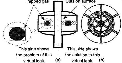
Fig. 51 An O-ring caused virtual leak.
Verifying that a real leak exists only tells you part of the story because there are four types of leaks. You must eliminate them by analysis of the symptoms, experience, the history of the vacuum system, and/or trial and error. The following are the four types of real leaks:
1. Virtual leaks
2. Leaks at demountable seals*
3. Real leaks through the walls of the vacuum system
4. Back-streaming from pumps
Virtual Leaks. A virtual leak is an honest-to-goodness leak, but because it is inside the vacuum system, it cannot be detected from the outside. A formal definition of a virtual leak is "a self-contained gas supply within a vacuum system." There are two types of virtual leaks:
1. Those leaks in which a gas is physically trapped (such as a gas which is poorly, or improperly, frozen or has had insufficient outgassing)
2. Those leaks where the gas is mechanically trapped as shown in Fig. 51 and Fig. 52
[Demountable seals are sections of a system that can be removed and replaced without damage to the system, yet maintain integrity of the system.]
If frozen gases within a cold trap are too close to the top, they are likely to evaporate as the liquid nitrogen level in the trap drops. This situation will cause the pressure in the system to rise and/or fluctuate (see Section 4.3). Different problems are caused when the wrong coolant is used for trapping such as when dry ice, rather than liquid nitrogen, is used as the coolant for a cold trap. If water vapor is in such a trap, the lowest possible achievable pressure would be 10^3 torr. This level is equal to the vapor pressure of water at the freezing temperature of carbon dioxide. If liquid nitrogen is used as the coolant, the system could potentially achieve 10^15 torr, the vapor pressure of water at liquid nitrogen temperatures.
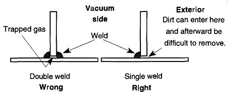
Fig. 52 Improper and proper welds for a metal vacuum system.
Although outgassing is one type of virtual leak, not all virtual leaks are results of outgassing. One example of a mechanically-caused virtual leak is the space trapped in the channels of an O-ring joint by a compressed O-ring. As you can see on the left half of Fig. 51 (a), an O-ring is compressed in the O-ring groove. In the blow-up seen at the left of Fig. 51 (a), you can clearly see the areas of trapped gas in the corners of the groove. Because these areas are at a higher pres sure than the system, they will "leak" into the vacuum. However, because they are contained within the system, it is impossible to find the leak from outside the sys tem. To prevent this type of virtual leak, the groove that supports an O-ring should be made without sharp corners. In addition, radial "pie cuts" can be made which allow gas passage. These cuts can be seen on the right half of Fig. 51 (a) and on the top view of an O-ring joint seen in Fig. 5l(b).
A second example of a virtual leak occurs in metal vacuum systems by a double weld being made instead of a single weld (see Fig. 52). Because only one weld should be required, a second weld can only lead to possible problems. The statement "If one is good, two is better" does not apply to this case. Incidentally, all welds should be made on the vacuum side of any given chamber. When a weld is on the outside, channels are created on the vacuum side. These channels can collect contamination that may be difficult or impossible to remove.
Demountable seals are sections of a vacuum system that are not permanently mounted. These seals include sections or pieces that can be moved or rotated such as traps, stopcocks, or valves. They differ from permanent seals, which are pieces of a vacuum system that are welded, or fused, together and cannot be separated or rotated without damaging the pieces or the system as a whole. Demountable seals require some material between the sections to be compressed, such as O-rings, grease, or gaskets that can prevent gases from passing. If there is inadequate or improperly aligned compression or cutting, or inadequate or improperly placed (or distorted) material to be compressed, or cut into, there will be a leak.
Leaks at Demountable Seals. These leaks are caused by wear, old stopcock grease, poorly applied grease, poor alignment, twisted or worn O-rings, inadequate stopcocks or joints, mismatched plugs and barrels, or dirt between pieces.
This list is by no means complete, but it gives you an idea of the range of problems.
Among the items that may be initially checked on a glass vacuum system are to ensure that all plug numbers of glass vacuum stopcock plugs match their respective barrel numbers. As mentioned on page 193, these numbers must match.* Another factor to consider with vacuum stopcocks is whether they are old, worn, or just defective. Additionally, you should examine that the vacuum stopcocks have been properly and recently greased.
One specific example of how leaks can originate in a demountable seal is the example of a worn standard taper joint being mated with a new joint. This situation can occur when an old cold trap bottom had been broken. The new replacement does not fit into the worn areas of the old, original member. If the worn areas (caused by the original members rubbing against each other for years) form a channel, a leak is created. In addition, standard taper joints and glass stopcocks can also be damaged by being left in HF, a base solution, or a base bath for an extended period of time. Unfortunately, the application of excess stopcock grease to cover up these imperfections is likely to create virtual leaks.
The advantage of O-ring joints is their easy demount-ability. However, if they are mounted unevenly or torqued unevenly, a leak can be easily created. Helium is readily absorbed into O-rings and result in long outgassing times. If previous leak detection was done on a vacuum line with O-rings, be prepared for such an occurrence. If a solvent is left in contact with an O-ring for an extended period of time, anything from swelling to destruction of the O-ring can result. This situation, of course, is dependent on the type of solvent and type of O-ring. One way to find out if there will be a problem with an O-ring and particular solvent is to pour some of the solvent in question into a small jar and drop in the type of O-ring you plan to use. Let it sit for several hours. If there are any effects, they should be obvious. A trick that can be used to provide limited protection from solvents is to apply a small dab of stopcock grease (select one not affected by that solvent) on an O-ring before assembly. Place a small amount of the protective grease on a Kimwipe and, while holding the O-ring in another Kimwipe, smear a thin film of grease on the O-ring. The grease will provide a limited protective barrier for the O-ring.
[The author has observed a system with two plugs and barrels mismatched that could not achieve a 1-torr vacuum. Once the plugs and barrels were properly matched, the system went to 10^3 torr in five minutes.
The author has also observed systems where the stopcocks looked perfectly good, but they had not been used in over a year. The user could not attain a vacuum better than 10^2 torr. Simply by regreasing all the stopcocks, the system went down to 10^5 torr within half an hour of restarting. In this situation, the poorly greased stopcocks could not provide adequate seals for a vacuum, but were able to prevent atmospheric moisture from contaminating the walls of the system. Thus, the system could achieve a reasonable vacuum in a short time.
The Kimwipe is not used to remove dirt from your fingers, although that benefit will also be realized. Rather, it is to prevent your skin oils from contacting the vacuum equipment. Skin oils can create virtual leaks from their outgassing.]
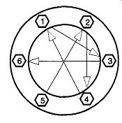
Fig. 53 Pattern for torquing bolts on metal flanges.
Ball-and-socket joints should not be used for high-vacuum systems because they are not intended for vacuum work. It is possible to obtain specially made ball joints with O-rings that are acceptable for some vacuum work. Some manufacturers supply sockets that have not been ground, and when used in tandem with ball joints with O-rings, they can achieve satisfactory vacuum performance.
Metal flanges require a gasket between their two sections. The bolts of metal flat flanges must be equally torqued by first tightening all bolts finger-tight. Then, using a wrench, you must tighten the bolts with less than a quarter turn each following the pattern shown in Fig. 53. When you arrive at the sixth bolt, repeat the same star pattern, but go to bolts 2, 5, 1, 4, 6, and 3 in turn.
Some flanges will have eight or more bolts. Use the same alternating pattern for making a proper seal. Continue with this rotational pattern until the bolts are tight.
If a metal flange has a knife-edge that cuts into a gasket, the gasket cannot be reused. No matter how well you try to line up the cuts with the knife-edge, it will not work, and it will leak. If you are desperate, you might try to have a machine shop remove the top and bottom surface of the gasket. However, experience has shown that this attempt is less than 50% successful for being leak-tight. Avoid using pipe threads whenever possible because they create long leak paths.
Long, thin leak paths require long time periods for leak verifications. If pipe threads must be used, do not use Teflon tape because it voraciously absorbs helium and will later thwart the use of a helium leak detector. Rather, use a small amount of thread sealant paste that contains Teflon (see Fig. 54). Glyptol, a common temporary leak sealant, is sometimes used as a pipe sealant. This sealant is not recommended because it ages and, after some six months or so, can develop a leak.
Thermocouples often come with pipe threads for attaching onto vacuum systems. Avoid using these pipe joints entirely by attaching a thermocouple to a glass system by silver soldering the thermocouple to a premanufactured glass-to-metal seal.
[ Use a cadmium-free silver solder and a suitable silver-solder flux. You will need a gas-oxygen torch to make this seal (see section 8 for information on gas-oxygen torches). Do not use a "hissy" torch flame because that indicates a flame too rich in oxygen. A soft blue flame is reducing and will prevent oxidation of the metal pieces, which prevents a good seal.]
It will be easier to assemble these pieces if you can set up the thermocouple and the glass-to-metal seal so that they rotate horizontally during the silver-soldering operation.
Leaks in System Walls. Real leaks in the walls of your system can occur along three different passageways:
1. A hole through the wall. A hole can be through a thick or thin wall and follow a straight or circuitous path. It can be represented as a door (large diameter compared to length of hole) or a tunnel (small diameter compared to length of hole).
2. A crack in the wall. This type of hole differs by having a much greater surface area of the hole channel. It can also show up as crazing of the surface (crazing is a collection of many small cracks).
3. The molecular structure of the wall allows the permeation of gas(es) through the wall itself.
The significance of these three pathways is how they affect leak detection. The longer and thinner a hole is, the more likely it will be plugged up by a probe liquid or even fingerprint oils. In addition, long, thin holes require lengthy leak testing.
Cracks, with their greater surface area, will retain a probe gas or liquid for a longer time. If a gas is affecting your work by permeating the walls of your vacuum system, you need to be more selective of the construction materials of your system.
[Fig. 54 Applying sealant to a pipe thread. From Introduction to Helium
Mass Spectrometer Leak Detection by Varian Associates, Inc. © 1980 by Varian
Associates, Inc., Palo Alto.]
Permeation of the walls itself is generally not a concern of a vacuum system within a research lab because a lab system can seldom achieve vacuums that are affected by gas permeation. Regardless, it can be resolved by selecting wall material better suited to the desired work.
The size of a leak is measured in the amount of gas (mass) that can be leaked within (per) a given unit of time (time). In the United States, the standard measurement is std cm^3/sec, or standard cubic centimeters per second. The term atm (atmospheric) std cm^3/sec provides the ambient pressure. This level can be important if a specific leak rate is relevant to a particular gas(es) at a particular pressure.
Most leaks have a viscous flow of gas. That is, the length of the gas's mean free path is such that a gas molecule is more likely to hit a wall before hitting another molecule. On a bell-shaped distribution curve of average leaks found, this size leak is between 10^5 and 10^3 std cm^3/Section The next most likely type leak is one in the transitional flow range of gas movement. Here, the molecules of gas are about equally likely to hit a wall as another molecule. This size leak is between 10^6 and 10^5 std cm^3/Section The least likely type of leak found is when the size of leak is so small that a sufficient vacuum is achieved to cause molecular flow in the region of the leak. This size leak is below 10^7 std cm^3/Section
Leaks up to the size of 10^5 std cm^3 /sec are not difficult to find in a laboratory vacuum system achieving a 10^6 torr vacuum. Below that range, baking the system may be required to fully open the leak from water vapor, fingerprints, or a host of other possible contaminants. Leaks smaller than 10^5 std cm^3/sec may not affect your system, but the amount of time spent in looking for these small leaks needs to be justified.
In vacuum systems, because measurements are usually made in liters/sec and pressures are stated in torr or Pascal, leak rates are known as torr-liters/sec, or Pa liters/Section These expressions are not equivalent leak rates, but they are proportional in the following ratios:
1 std cm^3/sec = 0.76 torr-liter/sec = 101.13 Pa liters/sec
1 torr-liter/sec = 1.3 std cm Vsec = 133.3 Pa-liter/sec
1 Pa-liter/sec = 0.0075 torr-liter/sec = 0.0098 std cm^3/sec
Backstreaming. There are two types of backstreaming; both are not desirable, but one can be quite deleterious. Once the vacuum system achieves its ultimate vacuum and is in molecular flow, gases from the system can drift back into the system. This is simply the results of equilibrium. On the other hand, if oils or vapors from the diffusion pump drift into the system, or oils from the mechanical pump drift into the diffusion pump, the effects are more profound.
Although a system typically will not act as if it has a leak until it is in the ultra vacuum range (>10^8 torr), at lower vacuum ranges (<10^6 torr) other complications from backstreaming can occur such as:
1. Silicon diffusion pump can coat and damage the filament of a mass spectrometer.
2. Mechanical pump oils (with their high vapor pressure) that drift into the diffusion pump can decrease its pumping efficiency.
3. Oils in a vacuum system can negatively interact with vacuum gauges (mercury can destroy thermocouple gauges and hydrocarbons on thoriated iridium filaments of hot-ion gauges require constant recalibration).
What can be limited is the backstreaming of condensable vapors. This can be achieved through the effective use of baffles, traps, and using good vacuum sys tem design. The simple resolution for backstreaming of condensable vapors from standard pumps is proper system design and proper maintenance of the traps.
If there are any pressure blips in the system and the mechanical pump cannot remove them fast enough, a diffusion pump will be swamped. That is, there is not enough backing pressure to maintain the gradient pressures within the diffusion pump and the gases contained within backstream into the system. The only prevention of this is to have a sufficiently powerful forepump and/or very good fore traps.
The maintenance of baffles and traps can be expensive both in materials and time. There are several dry pumps that have no grease or liquids in the pumping region.
Uncontrollable backstreaming can occur if there is a total system power failure that controls your vacuum system. If power in your building should go out and all mechanical pumping ceases, the efficiency of the traps and baffles to maintain a barrier in a static system will be tested. If someone is around at the time, close all stopcocks between each pump from any other and the stopcocks between the pumping system and the vacuum system.
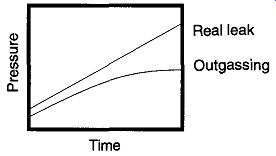
Fig. 55 A chart of a real leak versus outgassing as a matter of time.
6.5 Isolation to Find Leaks
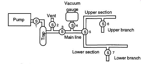
Fig. 56 A stylized vacuum system.
When a vacuum system is suspected of having a leak, one of the first tests is to determine whether the leak may be caused by outgassing. An easy way to deter mine this is to chart the rate of pressure loss versus time. To chart this rate, obtain the lowest vacuum you can in a reasonable amount of time, then close the section in question* from the pumping section by a stopcock or valve. Next, periodically over a few minutes, or an hour or two (or three), note the pressure and elapsed time. As seen in Fig. 55, a real leak will indicate a constant rate of pressure rise over time while an outgassing problem will indicate a decreasing rate of pressure rise over time.
[* A thermocouple gauge, Pirani gauge, or manometer must have access to the section being tested.] Once you have determined that you have a leak (as opposed to outgassing), you must then decide if the leak is virtual or real. If you know your system (and its history), you should be able to review your own operations, procedures, and activities to make this determination. On the other hand, if this system is new (to you) or there are a variety of people who work on the same system, then you may have to assume that there is a real leak and prove that it does or does not exist. Once you have proved that there is no real leak, and all other indications lead you to believe that a leak exists, you can assume that you have a virtual leak.
Regardless of whether a leak is real or virtual, the first step after a leak is verified is to isolate the area or section of the vacuum system that is leaking. This isolation decreases the time involved in locating the specific leak location. It's easier to play "hide and seek" if you know to look in a single room rather than the entire house. To find a leak's location, first examine major sections followed by smaller and smaller sections until you have the section in question. A stylized version of a vacuum system is shown in Fig. 56.
One of the best vacuum gauges to use when looking for a leak is a thermocouple or Pirani gauge. McLeod gauges, although very accurate, take too long to cycle through a reading. The ion gauges can only be used at good to high vacuums, which make their use irrelevant at the low vacuum levels that exist with large leaks.
In the stylized vacuum system shown in Fig. 56, one would go through the following process to locate a leak:
1. Close Stopcocks 5 and 2, and open Stopcocks 1, 3, and 4.
2. Once a vacuum is showing on the vacuum gauge, close Stopcock 4 and verify that the gauge is not leaking (this procedure may seem silly, but it caught me off-guard once). If the gauge leaks, you will be unable to check the rest of the system with any validity (that is why this step is important). If there is no leak, open Stopcock 4 and leave it open.
3. Close Stopcock 1. If the vacuum gauge shows a drop in the vacuum, the leak is somewhere within this area. If there is no leak, continue.
4. Open Stopcock 1 and then rotate Stopcock 5 so that the upper section is connected to the vacuum. Stopcock 6 should be closed. Wait until a vacuum is obtained and close Stopcock 1. If there is no leak, continue.
5. Open Stopcock 1 and then rotate Stopcock 6 so that the upper branch is connected to the vacuum. Wait until a vacuum is obtained and close Stopcock 1. If there is no leak, continue.
6. Open Stopcock 1 and then rotate Stopcock 5 so that the lower section is connected to the vacuum. Stopcock 7 should be closed. Wait until a vacuum is obtained and close Stopcock 1. If there is a leak, you must locate
and repair the leak before you can continue. It is important to continue, because there may still be a leak in the lower branch.
7. Open Stopcock 1 and rotate Stopcock 7 so that the lower branch is connected to the vacuum. Wait until a vacuum is obtained and close Stop cock 1. If there is no leak, go back to work-the system is checked and repaired.
As you can see, this process is aided or thwarted by vacuum system design.
Temporary isolation of the various parts of any vacuum system may be impossible by bad design. Therefore, be forewarned: If you are designing a vacuum system, provide a stopcock at every branch* of the system to aid in leak detection (section isolation not only helps in leak detection, but creates a more robust vacuum sys tem allowing greater control and protection).
Once you have isolated the part of the system in question, examine, re-grease, or tighten (if necessary) the stopcocks, joints, and other connections. In a glass system, look for cracks that may have developed on the tubing. You should look especially where the tubing has been worked, such as places where the glass is joined to another piece, or has been bent.
In searching for leaks, you must always look first for larger leaks followed by progressively smaller leaks. It makes sense: If you have some very large leaks (sometimes called "hissers"), there is no way a small leak will show up. However, if you have found and repaired some large leaks, do not assume that you are finished. You still may have leaks that can affect your work. Therefore, after repairing a leak, recheck your system for leaks. Just because you found one leak does not mean you've found them all.
[On the other hand, prevent unnecessary constrictions because they can limit gas flow and thereby slow system pumping speed. Therefore, do not use small stopcocks (such as 2 or 4 mm) along main lines, and do not place extra stopcocks along a tube for no purpose.]
6.6 Probe Gases and Liquids
Probe gases and liquids are often used in a variety of leak detection techniques.
Probe gases and liquids are materials not normally found within the vacuum sys tem, or at least not in the quantity created when they enter through a leak.
Turnbull defines four characteristics of the probe gas, vacuum system, and leak detector that affect the speed and effectiveness of leak detection:
1. The viscosity of the search gas, which governs the rate at which gas enters the leak
2. The speed at which the search gas is removed from the system by the pumping system
3. The sensitivity of the leak-detecting element to the particular search gas used
4. The volume of the system
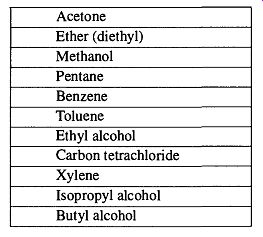
Table 14 Liquids Used in Leak Detection Rated Best (Top) to Worst (Bottom)
Although each of these factors can be considered individually, their effects on the speed of effective leak detection are cumulative. Materials that are less viscous will enter a given leak faster than those with greater viscosity. Materials that can be removed from the system faster will allow for faster verification. Materials that are easy for the detector to notice require less hesitation during detection. Finally, the smaller a system is, the less time that is needed for the probe gas to fill all areas.
When selecting probe gases (or liquids) and techniques to locate leaks, consider how they may affect your leak detection. Probe liquids are easy to see, easy to handle, and can be used with greater control, thereby providing an accuracy that is typically unobtainable with gases. Fiszdon [73] analyzed 12 different liquids that are commonly used in leak detection and developed the following list (in Table 14) of their merits for leak detection analysis. Note that the vapor pressures of the various liquids are irrelevant. Rather, low molecular weight and low viscosity are more important.
Probe liquids have their own peculiar problems. For example, although water will pass right through a large hole, it may effectively plug up a small, thin tunnel, giving the illusion that the leak is gone. In addition, a liquid may fill the entire surface of a crack causing a very slow removal (or "cleanup") of the indicator. Baking a system can reopen blocked holes and facilitate cleanup, but not all systems can be baked.
On the other hand, gases require special, cumbersome handling and often require you to enclose a given section of a vacuum system in some sort of bag.
Bagging can facilitate localizing the area of a leak, but cannot help in locating the exact location of the leak.
Do not use liquids for leak detection if you are considering using in a mass spectrometer further on in your experimentation. Liquids tend to have slow cleanup times and can severely slow down, or confound, future experimentation.
Thus some rules for the use of probe gases and liquids are as follows:
1. When possible, use a gas over a liquid.
2. Do not spray or squirt a liquid on. Use a cotton swab (or Kimwipe) to wipe it across parts of the system. In addition to safety, this method pro vides more control in finding leaks.
3. Solvents can damage parts of your system such as O-rings, causing a greater leak than the one you were originally trying to find. In addition, if the solvent drips on a water hose and creates a hole, you then have a water leak and a mess. If it drips on electric wires, you may have a short.
4. All of the chemicals listed in Table 14 are dangerous to breathe or have in contact with skin from short to extended periods of time. Some of the chemicals listed have severe OSHA restrictions for use without a fume hood, and some are toxic chemicals and should not be used at all (such as carbon tetrachloride and xylene).
5. Do not have any open flames or sparks while working on leak detection.
Unplug ion gauges and other electrical equipment.
6. Be sure to have plenty of ventilation and limit yourself to the first three liquids in Table 14. These liquids are (relatively) the safest, and they are the best from the list. Still, you should use a buddy system, and check with OSHA and/or local/state regulations to verify if there are any legal restrictions on the uses of any of these chemicals in your area.
7. When possible, select a low-vapor-pressure liquid over a high-vapor pressure liquid to provide faster cleanup time. In addition, non-polar solvents are more easily removed from glassware than polar solvents (for example, methanol vs. acetone).
8. When spraying probe gases on a vacuum system, be sure to start at the top with gases less dense than air and start at the bottom with gases denser than air.
Other aspects of Turnbull's four factors will be considered further in Section 6.9.
6.7 The Tesla Coil
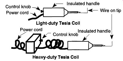
Fig. 57 The light- and heavy-duty Tesla coil.
If you have a glass system and can achieve a vacuum between approximately 10 to approximately 10^3 torr, then you can use a Tesla coil (sometimes called a "sparker") to look for moderate-size leaks. Because this range is the vacuum range of a mechanical vacuum pump, the Tesla coil provides an excellent tool for examining such systems.
The Tesla coil will ionize the gas molecules remaining in a vacuum system and cause them to glow. Above pressures of about 10 torr the gas molecules quench a discharge. That is, they are so close together they lose their extra energy by bumping into other molecules rather than giving off light. Below 10^3 torr, the molecules are too far apart and the mean free paths are too long to maintain a discharge.
As the tip of a Tesla coil is slowly waved within 1-3 cm of an evacuated glass vacuum system, the gases remaining will discharge with a glow characteristic of the gases within the system. If you bring the Tesla coil near a leak, a large white spark will jump from the tip of the coil to the specific leak spot. This event is very dramatic and demonstrates the location of a leak in a very effective manner. The spark is actually seeking ground, and the leak provides a path to the discharge inside the vacuum system. In turn, this discharge (which is an electrical conductor) provides a path to the mechanical pump for completion of the ground.
Metal components confound Tesla coil use: Their ground is easier to obtain than the ground found by passing through a glass leak and the poorer conducting discharge within.
There are a few limitations to the use of a Tesla coil:
1. It cannot be used near metal clamps or glass-to-metal seals on a glass system. The metal provides a ground for the electric discharge, bypassing the ionization of the gas inside the system.
2. A large quantity of very small holes may prevent you from obtaining a decent vacuum. However, none of the holes may be large enough for the Tesla coil to indicate a leak.
3. The self-contained Tesla coils often found in many labs are recommended by the manufacturers not to be used for longer than 10 minutes of continuous operation. If your needs require long continuous use on a consistent basis, heavy-duty Tesla coils are available that can be used continuously. These coils are easily identified because they have small boxes (approximately 5 in. x 5 in. x 8 in) connected to their hand-held sections. These hand-held sections are the same as those found on standard light-duty Tesla coils (see Fig. 57).
4. The Tesla coil will not find a leak within a demountable (seals such as stopcocks or joints) that is caused by poor application of grease or old stopcock grease that has sheared.
5. The Tesla coil should not be used near O-ring joints because the coil can destroy the O-ring by burning a strip across its side.
6. The Tesla coil should not be used near intentionally thin sections of glass (such as a break-off) because it can punch a hole through such a section.
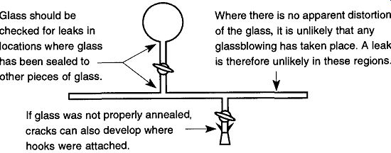
Fig. 58 Suggested areas of testing with a Tesla coil.
[An exception to this rule would be if a two- or three-fingered support clamp was overly tightened on a glass tube, causing the tube's wall to crack.]
It is unlikely that a leak could develop on a glass tube that has not received stress or that has not been worked on by a glassblower. Therefore to save time, simply pass the Tesla coil around areas where glass sections have been joined (see Fig. 58).* If there is a two- or three-fingered clamp in an area that needs to be tested, the clamp must be removed to properly check the seal. To spark check for cracks around hooks placed near a joint, place a rubber stopper in the end of the joint and then open up the stopcock to evacuate that section.
The spark from a Tesla coil is very powerful and can punch its way through thin sections of glass (see Point 6 above). Keep the coil away from known thin sections in which you wish to maintain integrity, such as break-offs. Most texts on vacuum technique recommend that the Tesla coil not be allowed to sit over weak areas for fear of "punching" a hole through the glass. This author disagrees with this reticence because if there is not a hole in a potentially weak area now, there may very likely be one in the area some time in the future. Therefore, go ahead and provide some stress while you are in a position to do something about any holes that develop. Otherwise a hole may develop either in the middle of an experiment or when repair and/or personnel are not available or as convenient. In addition, It is important that all gauge controllers be turned off before initiating Tesla coil test ing. The charge from the Tesla coil can destroy the controller's electronics.
Some extra Tesla coil tips are as follows:
1. Turn off some (or all) of the lights in a room so that any discharge from the coil can more easily be seen (it may also be necessary to close doors and/or cover windows). In addition, try not to face an open window.
2. A metal wire (such as copper or nichrome) wrapped around the tip of the Tesla coil (see Fig. 57) and bent in a right-angle can extend your reach and/or reach behind glassware.
The Tesla coil can also be used to make the vacuum line a discharge tube to light up probe gases or liquids. Gases or vapors in a vacuum will light up in specific colors from a discharge caused by a Tesla coil. A list of the colors that can be achieved with pure gases in a discharge tube can be seen in Table 15.
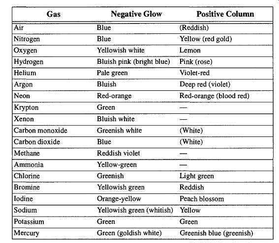
Table 15 Appearance of Discharges in a Gas Discharge Tube at Low Pressures
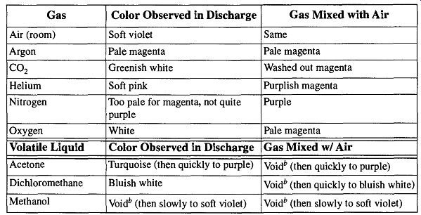
Table 16 Appearance of Discharges in Gases and Vapors at Low Pressures
When Excited by a Tesla Coil
Table 15 (found in several books or found as a similar table in other books on vacuum technology) provides the colors of pure gases from discharge tubes, which have very little to do with the discharge from the Tesla coil because of the following conditions:
1. The applied voltage and pressure can vary greatly.
2. The Tesla coil discharge, in leak testing, is a through-glass discharge, whereas a discharge tube is a metal-electrode discharge.
3. The distance between electrodes in a discharge tube is fixed, as opposed to the distance between the Tesla coil and ground (this distance can vary constantly from as little as several centimeters to many meters during leak detection). 4. The colors indicated in the tables are for pure gases. In a working vacuum system there will always be some air and moisture mixed with the probe gases. There will also be a trace amount of hydrocarbon vapors (from the mechanical pump) as well as other gases and vapors that incidentally may be in the system.
Work by Coyne and Cobb provided a more effective list of discharge colors because the colors were observed in the act of actual leak detection. They are presented in Table 16. Their work demonstrated that spraying gases had limited success in leak indication, but moderate success when the item being tested was enclosed within the gas (by way of a bag). Vapors from applied liquids provided better indicators and more easily demonstrated the specific location of a leak.
If you have items with glass-to-metal seals or metal supports you wish to leak check with a Tesla coil, you can encase them in a bag. Initiate a discharge with the Tesla coil while filling the bag with a test gas, such as oxygen or helium. This procedure can help to verify whether or not there is a leak. However, it will not help locate the leak. To specifically locate the leak, you may wipe a probe liquid, such as acetone on a cotton swab, over the suspected areas while a discharge is maintained in the system. If the discharge changes color, you have found the leak. If leaks are located far apart on a vacuum system, it is possible to find a leak while looking for others. However, leaks that are close together may appear, or act, like one. Therefore, after finding and repairing one leak(s), you should reexamine the area for other leaks.
When using this technique, turn off all lights and shut all windows (and doors) that allow light into the room. The darker your workplace, the more subtle the variations in the discharge may be observed. If your room can be brought to total darkness, you may want to place a small table lamp near where you are working.
Then, you will be less likely to bump into equipment as you make your way from the room's light switch to the testing area after turning the room lights off.
If you spray a probe gas lighter than air (such as helium) on a vacuum system, start at the top of the system. Start at the bottom with gases heavier than air. Otherwise, the drifting of the respective gases may provide false or inconclusive leak identification. It may be necessary to close windows and doors and might even be necessary to set up baffles to minimize drifting gases to prevent false or inconclusive leak identification.
Once a leak is verified and localized, pinpointing the leak can be done by taking an acetone-soaked cotton swab and rubbing it all around the section in question.
Once the acetone is wiped over the leak, there will be an immediate color change of the discharge to white or turquoise.
The shape and angle of a leak can have a significant effect on the time before a vapor is removed from a system and the colors of a discharge turn back to normal.
If the glass is very thin and the leak is perpendicular to the glass, the time for recovery can be very short (<10 seconds). On the other hand, if the glass is thick and/or the leak is on the diagonal through the glass wall, a leak can hold the ace tone for a period of time, even many minutes. Thus, the length of time necessary for the colors to go back to normal provides a clue as to the nature of the leak.
[Positive pressure cannot be used on glass systems because the pressure can cause glass stopcock plugs to blow out or joints to separate. The pressure may be sufficient for damaged to the system to occur.]
6.8 Soap Bubbles
As stated before, the Tesla coil cannot be used on metal systems. If a leak on a metal system is large enough to prevent you from using a mass spectrometer (or you do not own a mass spectrometer), you may be able to use positive pressure to locate leaks in a vacuum system.* Place the vacuum system under pressure with dry air, nitrogen, or helium up to about 60 psig. Then squirt a soapy solution on areas in question while looking for the formation of bubbles. This technique is the same that is used on all pressure systems and is even used by plumbers when installing gas pipe.
Some important rules are:
1. The gas used to pressurize a system should be clean and dry. Nitrogen and argon are very good because they are nonreactive gases. Do not use pure oxygen, especially if there are any greasy areas in the system because an explosion may result.
2. Any components that may be damaged by high pressure (i.e., ion gauges) should not be exposed to any pressure, or limit the pressure to 1 to 2 psig.
3. Watch out for fittings not intended to be used in pressure conditions.
4. Use a very bubbly solution (dish soap in water is good). Professionally made solutions such as Snoop or kid's bubble-blowing solutions work as well. Window-cleaning solutions are not recommended because they typically have non-foaming additives.
5. Apply the solution slowly and carefully so as not to create bubbles.
6. Do not immediately assume that there is no leak if no bubbles readily form; they may take a few seconds to an hour to form.
7. Use a waterproof marking pen or crayon to mark each leak as you proceed.
[* Soap solutions must be rinsed off of stainless steel because soap can corrode the metal.]
6.9 Pirani or Thermocouple Gauges
As mentioned in Section 5.14, many gauges read an inferred pressure, not real pres sure. Some vacuum gauges use the thermal conductivity of gases present in the system to infer the pressure of the system. These gauges are based on the concept that "less" gas will conduct "less" heat. Because different gases have different thermal conductivities, the user needs to make allowances if the gas in a system has a different thermal conductivity than the particular gas a gauge has been calibrated to use.
The standard reading for a thermionic gauge is based on air or nitrogen. If a probe gas is used whose thermal conductivity is higher (or lower) than air, its presence would be detected by the Pirani or thermocouple gauge as a change of indicated pressure. As would be expected, light gases with low viscosity can find smaller leaks. Hydrogen and helium are such gases, and they show a leak by an apparent increase in pressure because they have higher thermal conductivities than air. Other gases, such as argon, show an apparent decrease in pressure because of their lower thermal conductivities. The liquids in Table 14 can also be used with Pirani and/or thermocouple gauges because they can provide similar apparent changes in pressure.
Regardless of which direction the gauge varies, the important thing is that the gauge varies because the gauge is detecting a change from what was in the system before the probe gas (or liquid) was introduced. Sometimes there may be a slight drop in pressure caused by the liquid filling up a long, thin "tunnel" type of hole.
This drop is then followed by a rise (or depression)* in pressure as the vapors of the liquid affect the thermocouple. Do not expect equal swings of low followed by high pressure, because the causes of pressure swings are not related.
Another leak detection system that uses thermal conductivity is a gas leak detector that samples the air around the system being checked by a simple pump (often a diaphragm pump). The system under examination is filled with any type of gas (except combustible gases). Then, changes in the gas composition surrounding the piece being tested are "sniffed" by a probe. Any changes detected by a thermocouple within the detector are an indication of a leak, and the user is notified by a swing of a dial's needle (one way or another) and/or an audio alarm. The sensitivity of these devices varies depending on the probe gas used. Helium pro vides the best sensitivity. They are capable of detecting leaks as low as 10^5 atm/ sec, or, in other words, they can be used with simple vacuum systems.
One particular advantage with gas leak detectors is the constant distance from the leak to the thermal conductivity sensing device. This constant distance makes the time lag consistent wherever you are "sniffing" with the probe. When relying on installed thermocouples (on the vacuum system), a leak located right near the thermocouple will provide an immediate and full-strength response, whereas a leak some distance from the thermocouple will have a more subtle effect and will require some time before this effect is observed.
As is standard when using probe gases on the inside for detection outside, the greater the pressure exerted within the system being tested, the greater the sensitivity that can be expected from the detection device. With glass systems, it is not recommended to use a pressure greater than can be developed by attaching a bal loon filled with the probe gas to the system. It is possible to flow helium through the system before beginning the testing, but it then becomes necessary to wait until all the excess ambient helium in the room drifts off. Otherwise, there is too much helium "noise" in the room to allow for any sensitive readings. The wait could be minutes to hours depending on the size of the room, ventilation, and sloppiness of administering the helium to the system.
Do not breathe too close to the sniffing probe or its reference chamber because the CO2 from your breath could cause a deflection of the needle. If you are going to use a helium test gas after doing a bubble test, you must wait until the system is completely dry. The water will cause a negative deflection and the helium will cause a positive deflection, providing a combined weaker deflection. If, coincidentally, the water and helium are perfectly balanced, there will be no deflection.
Once a leak region is indicated, move the detector away from the system being tested and allow the needle to come to a normal position. Then you can go back in and zero in on the specific location.
[* If the thermal conductivity of the probe gas (or liquid) is higher than nitrogen (the base standard), the gauge will indicate a drop in pressure. If the thermal conductivity is less than nitrogen, the gauge will indicate an increase in pressure.]
(cont. to part 4)
Prev. | Next