AMAZON multi-meters discounts AMAZON oscilloscope discounts
1. The Dynamics of the Gas-Oxygen Torch
1.1 Types of Gas-Oxygen Torches
There are operations in the laboratory that require more flame heat than a Bunsen or Fisher burner can provide. For example, if you wish to fire-polish the end of a chipped glass tube or "seal off' (also called "tip off) a sample for NMR study, you will need to use a gas-oxygen torch.
A Bunsen burner burns methane (lab gas) and the oxygen available in air (=21%) and cannot provide sufficient energy to effectively work borosilicate glass, which makes up most of the glassware used in a laboratory.* To obtain more energy you must use a flammable gas (methane or propane), pure oxygen, and a torch that is specifically designed for this type of use. There are two torch designs for gas-oxygen combustion, one is known as a premix torch and the other is known as a surface-mix torch.
The designations premix and surfacemix refer to the region of the torch where (in relation to the tip) the gas and the oxygen are mixed before combustion. A pre-mix torch design combines the gas and oxygen in the neck of the torch before they reach the tip. A surface-mix torch keeps the gas and oxygen separated until they are mixed at the moment of combustion. Both types of torches are represented in Fig. 1. In addition to these designs, there are larger table models (of both designs) typically used by glassblowers. These table models are impractical for laboratory use because they are not portable and cannot be used for operations such as sealing off tubes.
[•Typically, the first opportunity that one has to do any glass work is making an eye dropper or bending a tube with a Bunsen burner. This is possible because the glass used was soda-lime glass. Most of the glassware used in the laboratory is borosilicate glass, which has a higher working temperature than soda-lime glass. For more information on the different types of glass used in the laboratory, see Section 1.1.5.]
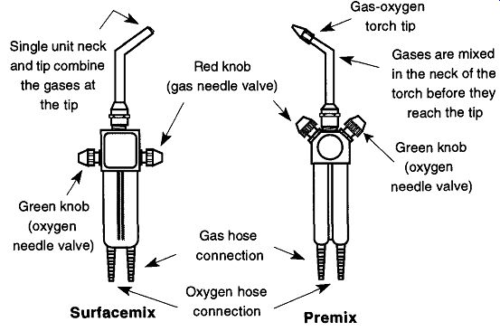
Fig. 1 Surface-mix and premix torch designs. The illustration of the surface-mix
torch is based on the Sharp Flame Hand Torch made by the Bethlehem Apparatus
Company, Inc. (Hellertown, PA 18055), reproduced with permission. The illustration
of the premix torch is based on the National Torch made by Premier Industries
(Fridley, MN 55432), reproduced with permission.
Superficially, the torches look similar. However, there are distinct advantages and disadvantages to both. The premix design is less expensive, and because it has one flame emitted from the tip (see Fig. 2) it is possible to obtain precise heating in one specific location. On the other hand, although it is possible to control the size and character of the flame to some degree by controlling the gas and oxygen flow, radical flame size changes require changing the removable tip with one of five different available sizes. In addition, the premix torch's flame is louder than the surface-mix torch.
Probably the biggest disadvantage of a premix torch is the characteristic of the torch to pop loudly when attempting to change the flame size or when turning the flame off. This popping sound will occur if the rate of gas combustion is faster than the gas flow rate from the tip. If the gas speed is too slow, the flame can enter the neck where premixed gas and oxygen are ready to instantaneously combust (explode) with a pop. This noise invariably does more damage to your nerves than anything else. If your torch has popped, turn off both oxygen and gas needle valves*, then open the oxygen valve until you hear a loud hissing noise for several seconds. Finally, close the oxygen valve and relight the torch. To prevent the pop, maintain steady and full gas and oxygen flow rates. For more of poping prevention, see Section 1.3.
[*Be sure to close the gas valve before fully opening the oxygen valve as the [greater] oxygen pres sure could force oxygen into an open gas valve and into the gas line where potential damage could occur if a "pop" is created.]
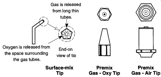
Fig. 2--The various tips of the surface-mix and premix torches.
When using the premix torch to work on borosilicate glass, use a gas-oxygen tip design, not a gas-air tip* (both tip designs are represented in Fig. 2). Using a gas-air tip with oxygen will cause a great deal of popping and may cause damage to the tip or torch. The gas-oxygen tip comes in a variety of types and sizes: "1 " is the smallest size, and "5" is the largest. A size "3" tip is a good, general-size tip for most needs around the lab.
The surface-mix torch (see Fig. 2) has a nonremovable, one-piece tip with multiple holes, or channels, that run the length of the neck. The oxygen passes to the tip using the area surrounding the gas tubes. This design prevents any mixing of the oxygen and gas until they meet at the tip, where combustion takes place.
These torches are impossible to pop, and glass tubing from sizes 4 to 35 mm can all be heated without changing the tip (there are no tips to change). The surface mix torch cannot be used as a gas-air torch.
In both torches, different flame sizes are obtained by controlling the amount of gas and oxygen. However, in the surface-mix design, you do not need to change tips to achieve the same range of flame sizes that are capable with the premix torch. On the other hand, the premix torch can achieve significantly smaller, and/ or more concentrated, narrower flames than the surface-mix torch. The premix torch's flame has a cooler hole in the center of the bushy flame, while the surface mix's bushy flame is more uniform throughout (see Fig. 3). Some people like the subtle heat variations that are possible in the premix design, while others prefer the uniformity of the surfacemix. All in all, the decision of which type of torch to use (surfacemix or premix) is based on the personal likes and dislikes of the user. For most laboratory uses, either is sufficient.
[*To use a premix torch with a gas-air tip, connect the hose connection for the green knob to a house air supply, or a tank of compressed air, rather than to the regulator of an oxygen tank.]
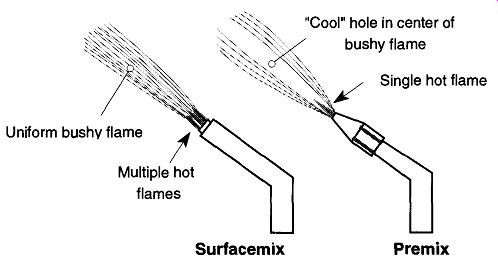
Fig. 3 Surface-mix and premix design flame characteristics.
The connection between the gas hose connection of the torch and the gas source can be made using Tygon, an amber latex, or any similar tubing used to connect gas lines in the lab (or a propane tank).* (The advantages and disadvantages of amber latex versus Tygon tubing are discussed on page 290.) The oxygen hose connection can also be connected using Tygon, a heavy-wall amber latex (1/4 in. 1/8 in.), or any similar tubing used to connect a regulator attached to an oxygen tank. Open any needle valve on the regulator fully to control the gas flow from the needle valve on the torch, not from the regulator. Paired tubing is available where one tube is red or orange and the other tube is green. This tubing can be handy to know which tube is carrying gas (the orange or red) and which is carrying oxygen (green). Laboratory gas pressure is typically so low that there is essentially no chance for gas pressure to blow the tubing off the torch. If the gas is from a propane tank, the pressure may be sufficiently great to potentially cause the tubing to be forced off. The same potential exists with the oxygen tube. However, if the oxygen regulator is set for about 5-10 lb. of delivery pressure, this is extremely unlikely. Regardless, to ensure safety, either a screw clamp can be placed on the torch barbs (hose connections) or some nichrome wire can be wrapped around the barb and secured tightly with a pair of pliers.
[*Acetylene should not be used on glass because it is a dirty gas and can leave undesirable deposits.
Before opening the main tank valve, set the outgoing pressure of the oxygen regulator to zero, then bring the pressure up to 5-10 lb. Too much pressure on the hoses can blow them off the hose connections or cause the tubing to expand like a balloon.]
1.2 How to Light a Gas-Oxygen Torch
Although it may seem straightforward, lighting a gas-oxygen torch seems to pro vide a challenge for a surprisingly large number of people. Probably the biggest mistakes in torch-lighting are either (a) not allowing enough time for the gas to reach the torch tip or (b) flooding the torch region with too much gas. The former is similar to turning on the shower water but not waiting for the hot water to reach the tub. The latter is simply not allowing enough air in the region to support combustion. A simple step-by-step process is as follows:
1. Be sure that any valves from the gas and oxygen supplies to the torch are open and that both gases are available.
2. Open the torch's gas and then oxygen valves for a second or two to purge any air that might be in the lines, then close them. There is a definable noise change when air has passed through the torch and gas has arrived. In addition, you can smell the gas. Neither of these aids are available with oxygen.
3. If you are using a match or lighter, first start the flame on the match (or the lighter), hold it near the tip of the torch, and then slowly open the gas (red) needle valve until you have a three- to four-inch flame.
4. If you are using a striker, slowly open the gas (red) needle valve about 1/4 to 1/3 of one revolution, then strike the striker several inches from the tip of the torch. Once the flame has ignited, set the size of the flame to three to four inches.
5. Slowly open the oxygen (green) needle valve until the flame is lightly hissing. If the flame is flickering and jumping around, increase the oxygen. If the flame is very thin and hissing loudly, decrease the amount of oxygen.
Note: You control the size of the flame with the gas and the character of the flame with the oxygen. The character of a flame refers to its shape of either a cool bushy flame (not enough oxygen) or hot-hissy flame (too much oxygen). If you make a major change of flame size, you will probably need to readjust the oxygen for the new flame size. Minor changes of flame size will maintain the same character.
1.3 How to Prevent a Premix Torch from Popping
Popping is caused when the flow rate of the gas leaving the tip is slower than the flow rate of the flame burning its way back into the tip. Once the flame enters the tip, it can ignite the gas and oxygen within (the tip) in an uncontrolled manner, resulting in an explosion and a loud "pop." The chance of popping a torch can be decreased by making sure that you always have a "hissing" to soft flame especially when decreasing the rate of oxygen or gas. A small, light fluttering flame is more likely to pop. Although annoying, the popping is not likely to do any damage to the torch, it is possible for a major pop to blow the flexible tubing off the torch's hose connections.
If a torch pops, a flame may continue to burn inside the torch, although this situation is not likely (a light whistling noise indicates that this condition exists). To extinguish an internal flame, first turn off the gas and oxygen needle valves on the torch. Then turn the oxygen valve forcefully open for a moment and close it. Do not maintain the oxygen on full with the gas valve open. The oxygen pressure from the compressed oxygen tank is more than likely greater than city gas pressure, and maintaining the oxygen in an open position for an extended time can force oxygen up the gas line. This can cause a major pop with dangerous potential consequences.
Finally, relight the torch and continue. Although they are not necessarily common occurrences, experience will help you avoid "pops." Because of the propensity for the premix torch to "pop," there is a recommended procedure for shutting the torch off. Even if you are capable of control ling the gas flow so proficiently that you never pop your torch, this procedure is still recommended.
1. Open the oxygen needle valve (CCW) fast and, just as fast, close the valve (CW) to increase the flow rate of the oxygen and blow the flame out. That is, once the flame is blown out, turn the oxygen off. Do not set up a condition where you are forcing oxygen up the gas line or you will potentially set up a large pop.
2. Turn off the oxygen.
3. Turn off the gas.
4. Turn off the source of the gas.
5. Turn off the oxygen tank.
Note: It is better to blow the flame out, and then turn off the gases than to turn off the gases before the flame is out to reduce the chance of the torch "popping." The surface mix torch does not require special shut-off procedures because the surface-mix torch cannot "pop." Therefore, it does not make a difference which gas you turn off first. There is also no reason to blow out the flame of a surface mix torch-besides, you cannot.
2. Using the Gas-Oxygen Torch
2.1 Uses for the Gas-Oxygen Torch in the Lab
The most common use for the gas-oxygen torch in the laboratory is to work on glass, and as anyone who has ever played with glass has found out, glass is not very forgiving. There are, however, a few operations that can be mastered by a non-glassblower, and "tipping off' (sealing off) a sample in an NMR tube is one of them.
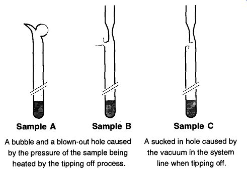
Fig. 4 Problems in tipping off samples.
It is also possible for a beginner to fire-polish laboratory glassware that has chipped or cracked edges. However, be forewarned: Any actions on broken or damaged glassware should be done with an "it is lost anyway" attitude. When inexperienced technicians try their hand at glassblowing, they learn fast that it's not as easy as it looks. But that does not mean you should not try. By accepting that any broken glassware is lost anyway, anything that survives the repair is bonus glassware. With time, as more experience is gained, more glassware will be saved. One of the most important pieces of knowledge that one needs to obtain with glass repair is the awareness of what you cannot repair.
2.2 How to Tip-Off a Sample
It is a common practice to seal a sample in a closed glass tube for storage or for further study by means of EPR (electron paramagnetic resonance) or NMR (nuclear magnetic resonance). Although it is not difficult to tip off a sample, if done poorly, the NMR tube will spin very badly. If done badly, the sample may be destroyed along with hours, weeks, or months of work.
When you heat glass to its softening temperature, two separate forces begin to control its behavior: surface tension (the material clings to itself, which is seen as glass beading up) and gravity (soft glass will sag under its own weight). A bead of glass will drip when gravity on the glass is stronger than the surface tension forces that hold it together.
There are two additional forces involved when tipping off a sample: gas pres sure buildup and vacuum from a vacuum system. Positive pressure is caused by inadvertently heating a sample (causing a pressure buildup), which makes it very difficult to seal off the sample. The possibility of a "glass aneurysm" or a rupture of the glass wall is likely from a positive pressure buildup (see Fig. 4, Samples A and B). On the other hand, if the sample is prepared on a vacuum line, and too much heating is done on one spot for too long, the tube will burst in rather than out (see Fig. 4, Sample C). Not only may this bursting destroy the sample, but allowing air into a vacuum line can damage or destroy parts or sections of the vacuum system.
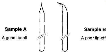
Fig. 5--Alignment is important when "tipping off."
Whether a sample tube is attached to a vacuum line or not, the easiest way to prevent a positive buildup of pressure is to freeze the sample with a slush bath or liquid nitrogen (depending on the solution's freezing temperature or what cool ants you have available). By freezing the sample solution, you accomplish three objectives: One, you protect the sample by protecting it from the heat of the flame; two, the sample is not likely to evaporate and thereby cause a buildup of pressure (and cause a pressure burst as shown in Fig. 4, Samples A and B); and three, the freezing will make a cryogenic pump that facilitates the tipping off pro cess by creating a vacuum. The sample must remain frozen during the entire tip ping-off procedure, so do not remove it from the coolant until the tipping off process is complete. A side benefit of the sample being frozen is that if there is a poor tip-off and air gets into the sample tube, with the sample being frozen, it is not likely to react with the air. If this occurs, keep the sample in the coolant until you are able to transfer it to another container. If you are using liquid nitrogen, you are likely to freeze some oxygen in the container, but it will be a liquid on top of the frozen sample. This can be pored off into a beaker at any time, to let it evaporate.
Figure 5 shows two examples of a tipped-off tube: Sample A is what you want, with the tipped-off section concentrically and linearly straight. Sample B is not acceptable because the tipped-off area is bent off from center. Because of this lopsided condition, the tube will not spin properly in an NMR machine.
Glass is a very poor conductor of heat, and therefore it is not possible to heat one side of a tube to be tipped off and expect to be finished. The only way to properly tip-off a sample tube is to heat it uniformly in the area to be tipped-that is, one side and then 180° to that area (see Fig. 6). The gradual heating is done by alternately heating opposite sides in a frequent and uniform manner. You must try to heat the entire area gradually and uniformly. Glass becomes soft before it becomes juicy. If one side becomes juicy too fast, there is a greater chance for the wall to suck in or blow out.
Whenever possible, before work begins, the sample tube should have a constriction made, where the tip-off will be made. The smaller the internal diameter, the easier the tip-off will be. Premade constrictions are shown on all the figures in this section.
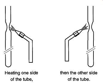
Fig. 6 You must heat both sides of a tube to obtain an even tip-off.
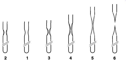
Fig. 7 Steps to a good tip-off.
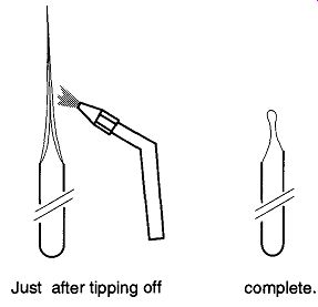
Fig. 8 Keep heat away from the sample.
The proper sequence of steps for making a tip-off is shown in series by Fig. 7 and listed in the following sequence:
1. The sample, before beginning.
2. As the tube begins to collapse, the walls begin to thicken.
3. The walls have collapsed to the point of closing off the lower section.
4. While heating only the middle of the closed section, start to pull the lower part of the tube down.
5. Continue pulling the lower section down while heating the middle of the section.
6. The middle of the section will become thin enough to be cut by the force of the flame.
It is possible to shorten the length of the point on the sample tube as long as you heat well above the closed section of the tipped-off area as seen in Fig. 8.
It is seldom possible to hold the lower portion of a sample tube with your hand as you tip it off. There is too much danger of burning your hand in any coolant or when heating the sample. However, by bending a pair of tweezers as shown in Fig. 9, it is easy to support any tube. Good-quality tweezers are made with hardened metal, and attempting to bend tweezer tips while they are cold may cause breakage. It may be necessary to heat the part of the tweezers that you wish to bend in a gas-oxygen torch flame to prevent breakage. After all bending is complete, reheat the entire section in the flame until it glows red and then immediately quench in water to re-temper the metal for hardness.
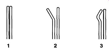
Fig. 9 Steps in bending the tips of tweezers to better support tubing.
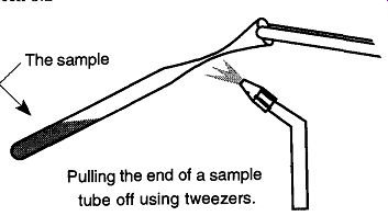
Fig. 10 Tipping off a sample not connected to a vacuum line.
There are times when you might do a tip-off of a tube that is not connected to a vacuum system, and it may not be practical to freeze the sample within the tube. In these situations you will not have a vacuum drawing the walls of the tubing in. Instead there will be only the pressure expanding the heated softened glass out. The trick is to do the tip-off as far from the sample as possible, and do it as quickly as possible. In addition, do not try to repair the tip-off after you are finished. This operation is a one-shot deal.
Rather than holding the torch as was done when the sample tube was stationary, here the torch should be mounted. The sample tube should be held in one hand and, with a pair of tweezers in the other hand, you must grab the open end of the sample tube. Now, alternately heat both sides of the tube end and pull off the end to seal the tube. The important point is not to dwell the flame on the tube and heat the solution, thereby raising the pressure inside the tube (see Fig. 10).
This "open-tube technique" should never be done on flammable solutions unless the sample is frozen!
Practice tipping off sample tubes that mimic the condition and environment of a real sample before you try with an important sample. In other words, try this procedure with the solvent that you plan to use (i.e., if water is the solvent of your material, practice with water), attached to the same vacuum line you plan to use, and in the state it will be in when you will be doing the tip-off (such as frozen in liquid nitrogen). Remember to keep the flame of the torch away from the walls of the Dewar containing the liquid nitrogen.
2.3 How to Fire-Polish the End of a Glass Tube
Chipped and broken ends of tubes are common sights in the average laboratory. Because it is easy to repair this dangerous and unnecessary situation, there is no reason not to take a torch in hand and repair the problem. However, there are a few limitations involved:
1. If the glass is thicker than 2 to 3 mm (3/32 to 1/8 in.), do not fire-polish the glass because you are likely to cause more damage than already exists. The heat-induced strain caused by the gas-oxygen torch is likely to crack the glass after it cools. Some examples of glass that should not be fire-polished are bases of graduated cylinders or rims of funnels (see Fig. 11).
2. If there are crack lines radiating from a broken section (see Fig. 11), fire-polishing by an inexperienced person is not advised, and should not be done with great expectations. Under the heat of a flame, cracks tend to spread far beyond your wildest imagination or your worst fears.
Safety Note: This manual is not meant to teach glassblowing because there are already several excellent books for that purpose (see Section D).
If you have an oven that can obtain temperatures of 565 °C (1049°F) or greater and is big enough to contain the entire piece that you have fire-polished, you should formally anneal any piece you repair. After placing the entire piece in the oven, bring the oven's temperature up to 565°C, hold that temperature for about 15 minutes, and turn the oven off. It is best to leave the piece in the oven until it reaches room temperature, at least three to four hours or simply overnight.
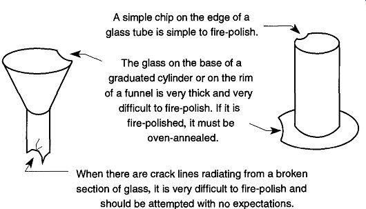
Fig. 11 Problem repairs of broken glassware.
2.4 Brazing and Silver Soldering
The high heat that the gas-oxygen torch can deliver allows it to be used for both brazing and silver soldering. However, because you can vary the gas and oxygen content of the flame, you can provide either an oxidizing or reducing environment to your work. Because brazing and silver soldering cannot be done with oxide on the material's surface, using an oxidizing flame will prevent a good seal.
Normally a flux is used to remove oxides from surfaces when brazing or soldering, and a gas-oxide torch also requires the use of a flux. However, if the flame is oxygen-rich, as the flux is boiled or burnt off, the excess oxygen from the torch will oxidize the metal's surface before the solder can wet the surface. In a reducing flame, as the flux is boiled or burnt off, the reducing flame will maintain the pure metal until the solder can flow over and wet the surface.
To make a reducing flame on a gas-oxygen torch, simply cut back the oxygen flow until it has a soft or fluffy character. If you see a bit of yellow in the flame, you will need to increase the oxygen a tad. There may be a desire to increase the oxygen flow to obtain a hot 'hissy' flame to get the metal hotter so the solder will flow. Unfortunately, this flame is the oxidizing flame that will prevent the solder from wetting the metal and completing the brazing or soldering operation.
Prev. | Next