AMAZON multi-meters discounts AMAZON oscilloscope discounts
This short section deals with a range of devices used in electronics, describing them briefly and outlining their functions. For various reasons the devices dealt with here are not covered elsewhere in the book, perhaps because they are outside the mainstream of electronics technology, or perhaps because they are components not generally regarded as 'electronic'. Nevertheless, this ragbag of items will prove of use and interest to the electronics engineer.
1. SEMICONDUCTOR DEVICES
Thyristors
The thyristor, or silicon controlled rectifier (SCR), is a component that has wide applications in the field of power control. In essence it is a very simple component, easy to use and easy to understand. The circuit symbol for the SCR is given in Fig. 1. The circuit symbol is clearly reminiscent of the diode, and the SCR is indeed a form of diode. However, it will, under normal circumstances, fail to conduct current in either direction.
The SCR can be made to withstand high voltages, and there are various designs that can be operated with a peak voltage of 50 V to tens of kV.
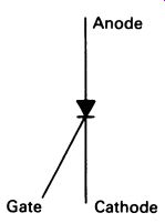
FIG. 1 circuit symbol for a thyristor (SCR)
If a voltage is applied to the SCR in such a way that, if it were a diode, it would conduct (forward-biasing it), and a small current is made to flow between the gate and cathode, the SCR will abruptly change from a non conducting to a conducting mode, with characteristics similar to those of a forward-biased silicon diode. The forward voltage drop is generally higher, typically 0.7 to 13 V. Turn-on takes place rapidly, within a few microseconds of the application of the gate current. Once turned on, the SCR will remain in the conducting mode, even if the gate current is removed.
Once triggered into conduction, the SCR will turn off again only when the current flowing through it is reduced below a certain value. This minimum current required to maintain conduction is called the holding current, and is between a few microamps and a few tens of milliamps, according to the type of device.
Thyristors are useful for controlling alternating current mains supplies, and are used in most lighting-control applications. For simple on/off circuits, the thyristor is placed in series with the circuit to be controlled.
When the circuit is to be switched on, a gate current is applied; this principle is used in the photoelectric light control illustrated in Figure 16.11 (p. 244). An obvious limitation of this circuit is the fact that the a.c. supply is rectified-the lamp will be on at a lower brightness than usual, and some kinds of lamp or motor will not work at all. In the commercial design of Figure 16.11 a benefit is made out of this near-necessity--'extends the lamp life' --but in other circuits full control of alternating current is essential.
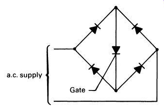
FIG. 2 the thyristor can be used to give full-wave control of an
a. c. supply by the use of a bridge rectifier circuit
This can be obtained by using a bridge rectifier arrangement, so that the current is applied to the SCR in the proper sense for both positive and negative cycles of the a.c. waveform (see Fig. 2). Circuits like this are possible because the thyristor is turned off every cycle, when the mains voltage crosses the zero line. With the gate signal removed, the SCR will turn off at the end of that half-cycle of the a.c.
The SCR is a power-control device, and as such it is made in a variety of sizes, from small devices capable of handling a few hundred milliamps at 50 V to huge units designed to deal with hundreds of amps at hundreds of volts. Small SCRs used in electronic circuits likely to be encountered by the engineer range from T092 encapsulated 300 mA versions up to about 40 A. Voltages are usually in the range 50-1200 V, with 400 V models preferred for control of mains electricity. It must, however, be emphasized that much larger devices are used in power applications. Gate currents the minimum amount needed to trigger the SCR-range from a few hundred microamps for sensitive low-voltage SCRs, to a few tens of milli amps for the larger ones.
Triacs The triac, to give the more usual name for the bidirectional thyristor, is just what it sounds like. It is an SCR that will conduct in either direction, with the gate current flowing between anode 1 and the gate in either direction a most flexible component. The circuit symbol is given in Fig. 3.
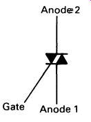
FIG. 3 circuit symbol for a triac
The triac can be used as a direct substitute for the SCR in the circuit in Figure 16.11, with anode 1 in the same position as the SCR cathode. The gate resistor, controlling the gate current, may need to be reduced a little from 1.8 k-Ohm, as triacs tend to need rather higher gate voltages than the equivalent SCR. With the triac replacing the SCR, the circuit will switch the lamp on at full brightness, like the SCR, the triac will remain on, once triggered, until the current passing through it falls below the level of the holding current. When the triac is operated with mains electricity, this occurs once every half-cycle, or 100 times a second with a 50 Hz supply frequency.
Diacs
The diac is a specialized component, specifically designed for use with SCRs and triacs, though it has inevitably found its way into various other circuits. The 'long' name for the diac is the bidirectional breakdown diode, and its circuit symbol is given in Fig. 4.
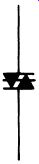
FIG. 4 circuit symbol for a diac.
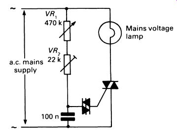
FIG. 6 a functional circuit for phase control of an a.c. lighting
circuit; this circuit will operate, but is likely to cause radio frequency
interference.
The diac normally blocks the flow of current in either direction, but if the voltage across it is increased to the breakover voltage, usually about 30 V, the diac begins to conduct. It does in fact exhibit a phenomenon known as negative resistance, for as breakover occurs the voltage across the diac drops by a few volts. It the diac is connected in a circuit in which a steadily increasing voltage appears across it, it will, at breakover, allow a sudden current 'step' to flow in the circuit. Fig. 5 shows this in graphical form.
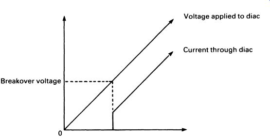
FIG. 5 a voltage and current for a diac
The diac is an ideal device for providing a suitable trigger pulse for an SCR or triac, and an applications circuit for a mains lamp brightness controller is given in Fig. 6. This simple circuit is not recommended as a construction circuit, partly because mains voltages are present and stringent safety precautions have to be taken (for example, most potentiometers have the shaft live to the brush, and thus live to mains), and partly because it is electrically 'noisy' and produces radio interference. In commercial units-cheap because of mass production-radio frequency interference suppressors are fitted.
The circuit works by means of what is loosely known as 'phase control'. As the voltage across the circuit rises, following the a.c. waveform, the capacitor gradually charges up, at a rate controlled by VR 1 and VR2. At a certain point in the a.c. half-cycle the voltage across the capacitor will reach the breakover voltage of the diac and the diac will apply a pulse of current to the triac gate, triggering the triac into conduction and allowing current to flow through the load. At the end of the half-cycle the triac will switch off.
During the next half-cycle, the same sequence will occur, but with all the polarities reversed (unimportant, because all the circuit components will work with a voltage applied in either direction). Once again, the triac will trigger after a certain delay, allowing a current flow through the load.
If the resistor VR 1 is set to a high resistance, the capacitor will charge up slowly and the triac will be triggered near the end of each half-cycle.
If the resistor VR 1 is set to a low value of resistance, the triac will be triggered near the beginning of each half-cycle, applying almost full power to the load. The amount of power flowing through the load is controlled by VR1 , so the brightness of a lamp can be regulated over a wide range.
Because the circuit works by switching the power on and off, little heat is dissipated and the control is efficient in terms of power used. VR2 is included in this circuit to set the maximum brightness level according to the characteristics of the diac and triac; a production model would use a fixed resistor. This mode of power control is illustrated graphically in Fig. 7.
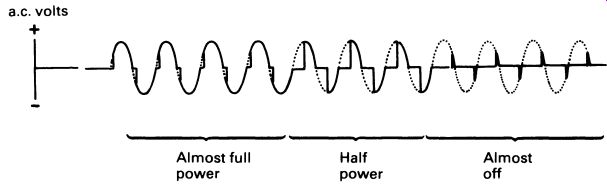
FIG. 7 illustrating the way in which the triac can be used with
an a.c. supply to control the amount of power flowing through a load
As we saw in Section 16 on optoelectronics, it is possible to make most semiconductor devices photosensitive just by using transparent encapsulations and optimizing the design to allow light to fall on a sensitive junction. Photo thyristors and photo-triacs are therefore available, and these can be triggered in the normal way, or by ambient light rising above a certain level.
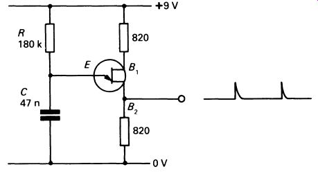
FIG. 8 a unijunction oscillator
Unijunction transistors
Unijunction transistors (UJTs) are used primarily in oscillators. A typical unijunction oscillator is shown in Fig. 8.
The UJT has three terminals, two bases and an emitter. The UJT in the circuit is an n -channel device; p -channel UJTs are available but uncommon (the circuit symbol has the arrowhead reversed for the p-channel version). The UJT normally exhibits a high resistance between the two bases, about 10 k-Ohm. If the emitter is at a low potential relative to B1, the emitter-B1 junction behaves like a reverse-biased diode, and negligible current flows through the emitter circuit. If the emitter potential is increased, to a point approximately equal to half the voltage between B1 and B2 , the emitter-B1 junction suddenly becomes forward-biased and the emitter--B1 resistance falls to a very low value. In the oscillator circuit illustrated, the timing is controlled by R and C (similar to the circuit in Fig. 6 above). When the UJT conducts, the capacitor is discharged very rapidly through the emitter-B1 junction and the 820 ohm resistor. An output taken from B1 therefore consists of a series of short pulses at the required frequency.
Thermistors
Used in temperature-sensing applications, thermistors are semiconductor resistors which change resistance with temperature. There are two types: negative-resistance temperature coefficient (NTC), in which the resistance decreases as temperature increases; and positive-resistance temperature coefficient (PTC), in which resistance increases with increasing tempera ture. Circuit symbols are given in Fig. 9.
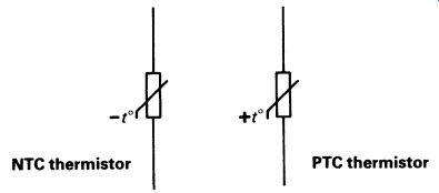
FIG. 9 thermistors
Voltage-dependent resistors
Voltage-dependent resistors (VDRs) are used in a few applications only. A VDR is simply a resistor whose resistance decreases as the voltage across the resistor increases. VDRs can be used to give a degree of voltage stabilization in circuits operating in the same way as a Zener diode regulator.
Because the VDR shows a gradual increase in conduction with increasing voltage, the regulation possible is not as accurate as can be achieved with a Zener. However, VDRs can be made with high resistance and high operating voltage, so they are still used in high-voltage regulating systems. The circuit symbol for a VDR is given in Fig. 10.
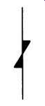
FIG. 10 circuit symbol for a voltage-dependent resistor (VDR) A
VDR connected across a power supply will also provide a measure of protection
from transient high-voltage peaks. The VDR is chosen to have a very high
resistance at the supply voltage, but to have a low resistance at the
high voltage levels associated with transients that might cause damage
to the circuits the VDR is protecting.
Hall-effect devices
Named after the discoverer of the fact that magnetism could affect charge carriers (holes and electrons) in a solid, Hall-effect devices are semiconductors that react to an external magnetic field. These devices are sensitive not only to the existence of a magnetic field but also to its polarity.
Hall-effect devices are used for the measurement of magnetic fields, and also as switches, where they make a useful alternative to mechanical and optical switching systems.
A Hall-effect element is commonly included in a Hall-effect switch, in which an IC is used to provide positive on/off switching. An example is the TL172C, which is packaged in a standard T092 encapsulation. Normally the output is off, with a maximum current flow from the output of 20 p.A. When the magnetic field through the device reaches about 50mT (milli Teslas) it abruptly switches on, and up to 20 mA can be taken from the output.
2. ELECTROMAGNETIC DEVICES
Relays
Relays were among the first electrical components used as amplifiers, and were widely applied to early telegraph networks. A relay consists of an electromagnet-a number of turns of insulated wire wound on a soft iron core-that operates some sort of mechanical switch. Soft iron is used for the core because it does not retain magnetism easily. A simple relay is illustrated in Fig. 11.
In a telegraph system, in which pulses of current are sent at a low rate of repetition, a relay can be used to amplify signals. The principle is shown in Fig. 12.
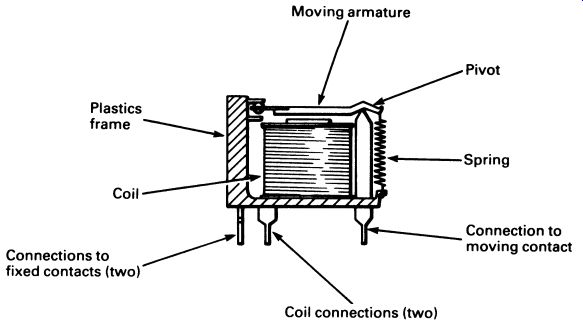
FIG. 11 a small changeover relay.
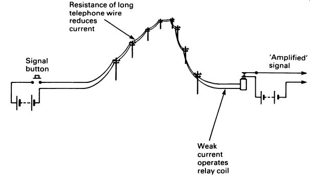
FIG. 12 a relay used as an amplifier in a telegraph system.
There is no reason why the relay should not work more than one con tact, nor is there any reason why contacts should not be normally closed (to open when the electromagnet is energized) rather than the more usual 'normally open' form. Various circuit symbols are used for relays, and Fig. 13 shows two of them. Both relays are shown with two pairs of contacts, one normally open and one normally closed. It is conventional to draw the contacts in the positions they adopt with the coil unenergized.
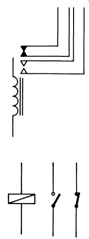
FIG. 13 circuit diagrams used for relays
It is not always convenient to represent the relay contacts as neatly as in Fig. 13 since a relay may have several sets of contacts controlling widely separated circuits; in this case the contacts are drawn in a convenient position, and are clearly labeled as belonging to a particular relay coil.
Relays come in an amazing range of sizes. At one extreme are huge machines in power stations and distribution systems, switching thousands of amps at thousands of volts. At the other end of the scale there are tiny low current relays that are encapsulated in a TOS can, for printed circuit use.
Reed relays
The magnetic reed relay is a fairly new device, developed for telecommunications before solid-state switching became possible. The reed relay was produced as a cheap and extremely reliable method of switching a low power signal.
The reed consists of two springy blades of ferrous metal, sealed in a glass envelope full of inert gas. The blades are mounted so that they are not quite touching, about 0.5 mm apart. A reed switch is shown in Fig. 14.
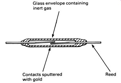
FIG. 14 a 'single make' reed switch --- Glass envelope containing
inert gas
If a magnetic field is brought close to the reed switch, the reeds become temporarily magnetized, and stick together, completing the circuit. When the magnetic field is removed, they spring apart again and break the connection. A reed relay is made simply by winding a coil round the outside of the reed switch. When a current flows through the coil, the induced magnetism makes the reed switch close.
The ends of the reed are coated with gold, and this, combined with the inert gas, prevents the contacts corroding. The reed relay is very reliable, and is fast in operation, closing in about 1-2 ms, and opening in less than 0.5 ms. Reed relays should not in general be used with inductive circuits, as arcing will damage the thin gold layer and may even weld the contacts shut.
Changeover reed switches are also common, and are constructed as shown in Fig. 15.
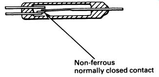
FIG. 15 a changeover reed switch
Reed relays are commonly encapsulated in DIL packs, which makes them ideal for printed circuit use. There are still occasions when a relay is the best answer to a design problem, providing as it does complete isolation between circuits, and a capability of switching alternating or direct currents. Two DIL reed-relay pin diagrams are given in Fig. 16.
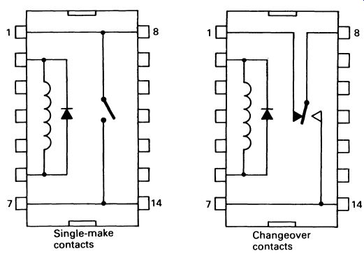
FIG. 16 pin-connection diagrams for two types of reed relay
Solenoids
Where it is required to change electrical power into linear mechanical motion, a solenoid may be used. It is simply a coil wound round a suitable former, with a soft iron core free to move inside. When the coil is energized, the core is pulled into the coil by the magnetic field produced by the current flow. Solenoids are used to operate the mechanical parts of some cassette tape transport mechanisms, for instance. Solenoids are not particularly efficient in their use of power, and a large current is required if useful mechanical work is to be done.
Speakers
The speaker is, in reality, a solenoid. A typical speaker is illustrated in Fig. 17.
A powerful magnet surrounds the speech coil, which is connected to the amplifier, etc., driving the speaker. A current flowing through the coil in one direction pulls the coil back into the magnet, whereas a current flowing through the coil the other way will push the coil out of the magnet. When the speaker is connected to the output of an audio amplifier, the movements of the coil will duplicate the waveform of the amplifier's output.
In order to produce a loud sound output, the coil has to move a reason able volume of air, so the speaker cone is quite large, as large, in fact, as is practical. The movement of the cone, which has to be rigidly fixed to the coil, causes vibrations in the air-alternate compressions and rarefactions which reproduce the sounds fed into the audio system.
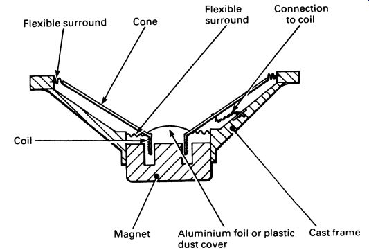
FIG. 17 cross-section through a speaker
The design of speakers has been given a great amount of attention in the search for a speaker that will give the highest possible fidelity. Although a small speaker can reproduce the audio spectrum (the range of sounds that are audible to humans) reasonably well, it cannot provide the best possible fidelity across the whole range. Hi-fi systems therefore use two or three speakers, along with a simple electrical filter system to split the signal between the two or three speakers, according to frequency.
A bass speaker, for example (known as a 'woofer' in the hi-fi world), must move a lot of air to reproduce low bass sounds with sufficient volume. A large cone is necessary, or if the size requirement of the speaker cabinet does not allow this, then a small cone that has a large excursion (i.e. it moves in and out a long way) will suffice.
A treble speaker (known as a 'tweeter') does not have to move as much air, but in order to reproduce high frequency notes the cone must move very quickly. The large-and consequently heavier -cone of the bass speaker has too much inertia to move rapidly backwards and forwards, and so could not be used as a tweeter. Tweeters have small, very light weight cones, with relatively little travel.
In both types of speaker it is necessary for the cone to be rigid; this is especially important in bass speakers. If the cone flexes as it moves, the additional vibrations that result will make the sound distorted.
Another factor is the amount of power that the speaker can (i) handle without distortion, and (ii) dissipate. All the output power of the amplifier is radiated by the speaker, most of it as heat (just a little as sound), and the coil must be capable of radiating the energy without melting. If a speaker is overloaded by a too-powerful amplifier, the cone may reach the limits of its travel, causing severe distortion.
The box, or enclosure, into which the speakers are fitted is also import ant for hi-fi work. The volume of air behind the speaker cone acts as a cushion for the cone, and damps its vibrations. Various reflections within the enclosure can also affect the sound, to a surprising extent.
Piezoelectric sounders
Where a 'bleep' is required, rather than an undistorted speech or music output, piezoelectric sounders may be used instead of small speakers.
Applications are computer sound output systems, keyboard bleepers, small alarm bleepers and electronic alarm watches. The piezoelectric sounder is no more than a small piece of piezoelectric crystal, sometimes with and sometimes without an extra 'cone' (which, being flat, is referred to as a diaphragm). Low-voltage electrical signals applied to the crystal will make it flex, so a suitable audio frequency waveform will cause an audible output. Piezoelectric sounders are small (or very small), cheap, and not very loud.
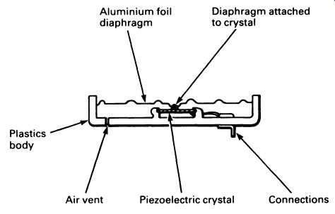
FIG. 18 a crystal microphone
Microphones There are three main types of microphone in common use: crystal, moving coil and capacitor. The cheapest is the crystal microphone, which is very similar in design to the piezoelectric sounder. A simplified drawing of a crystal microphone is given in Fig. 18.
Sound waves hitting the microphone will move the diaphragm in sym pathy with them, flexing the diaphragm. The diaphragm moves the piezo electric crystal, which generates an electrical output that is an analog of the sound waves. Crystal microphones characteristically have high voltage outputs-relatively speaking, for the crystal microphone may produce a few millivolts. The crystal microphone has a high internal impedance several megohms-and so is not suitable for use with bipolar transistor amplifiers. FET amplifiers can be used, as these have high input resistances. The crystal microphone actually 'looks' to the amplifier like a capacitor of around 1-2 nF. The output of the crystal microphone is not particularly linear, so it has been replaced in most common uses by the moving-coil microphone.
Moving-coil microphones are made in a wide range of sizes and prices, from cheap models supplied with inexpensive cassette recorders to more expensive 'studio' microphones that have a very high audio quality. Fig. 19 shows a simplified drawing of a moving-coil microphone. The con struction is not unlike a speaker. Sound waves move the diaphragm, which is fixed to a lightweight coil. The coil is surrounded by a magnetic field, so as it moves a current is induced in the coil, which accurately mirrors the sound waves.

FIG. 19 a moving-coil microphone
The coil impedance decides the impedance of the microphone. There are physical limits on how many turns of wire can be used, and for this reason most moving-coil microphones have a standard impedance of 200 n.
This is suitable for matching both bipolar and FET amplifiers. The output of the moving-coil microphone is small, at most a millivolt. Moving-coil microphones are cheap and efficient, and can give good sound.
The most recent addition to the range of commonly used microphones is the capacitor microphone, which recent advances have brought out of the broadcast studio and into even the cheapest cassette tape-recorders.
The capacitor microphone utilizes an electret element, which is a special capacitor with one 'plate' being a flexible diaphragm. If a voltage is applied to the electret element, the capacitor is charged, and there is no current flow apart from a negligible leakage current. However, sound waves hitting the diaphragm change the amount of capacitance (which depends, you may remember, on the spacing between plates). The amount of charge on the capacitor does not change, and as the capacitance varies so the voltage across the capacitor varies to maintain a constant charge. An integral IGFET preamplifier provides a current output and a typical impedance of600U. Electret capacitor microphones give a high output compared with other types, and the sound quality is excellent. It is necessary to provide the electret element with a polarizing voltage, to charge the capacitor; this is conveniently done with a 1.5 V battery, an HP7 size cell lasting more than a year. The smallest electret microphones are very tiny, powered with button-sized mercury or silver-zinc cells. A simplified diagram of a capacitor microphone is given in Fig. 10.
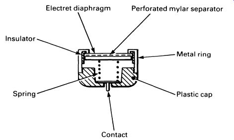
FIG. 20 a capacitor microphone. Electret diaphragm, Perforated mylar
separator, Insulator, Spring, Plastic cap.
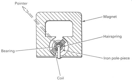
FIG. 21 a moving-coil meter
Meters
The last item under 'electromagnetic devices' is the meter. Although 'moving-needle' meters have been replaced in many applications by digital meters or bar graph displays, meters are still used in a variety of measuring and indicating applications.
Most meters are of the moving-coil variety, illustrated in Fig. 21.
The operation is straightforward and should be familiar. A voltage applied across the moving coil causes the moving coil to rotate on its bearings, against the returning pressure applied by the hairsprings. The coil will stop at a point where the increasing force of the hairsprings is exactly balanced by the magnetic forces. The more current passing through the coil, the further it will turn. A needle fixed to the moving coil moves along a scale, which can be calibrated according to the user's requirements. It is convenient to use the hairsprings to take the current to the coil. Other types of meter are seldom used in 'electronics' applications.
QUESTIONS
1. Draw the circuit symbol for a thyristor, and describe the important points about the device's operation.
2. Sometimes a VDR is used instead of a Zener diode for voltage regulation or limiting. Suggest two circumstances in which the VDR is to be preferred.
3. What advantages does a reed relay have over a conventional mechanical relay for telecommunications applications?
4. Why do hi-fl systems generally have more than one speaker in each enclosure?
5. Make a sketch of a circuit in which a relay is used to operate a triac.
The triac is switching a mains lamp on and off. The relay provides isolation for the control circuit, which takes the form of a light operated circuit, powered by a battery.