by Richard Fermoyle
A solid-state wall switch that "remembers" to turn off the lights when you forget!
HAVE YOU ever gone into a darkened room "for just a minute," only to return an hour later and find the lights still burning? The "Smart Switch" presented here will correct this most common occurrence.
This useful project, which costs about $17 to build, is a solid-state, 117-volt ac timer switch designed to replace a conventional wall switch. Using the components specified, the Smart Switch can control loads up to 250 watts.
When a pushbutton on the Smart Switch is depressed, power will be supplied to the load (lights) connected to it for approximately one minute. At the end of that interval, power will be automatically removed. An optional bypass switch is provided to override the timer circuit and to power the load continuously. With today's high cost of energy and the need to conserve, this device is a practical and economical addition to your home.
About the Circuit. The Smart Switch is shown schematically in Fig. 1. The heart of the circuit is IC2, a 555 timer operating as a monostable multivibrator.
When pushbutton switch S1 is depressed, power from the 117-volt ac line is applied to the timer circuit. Parallel resistors R3 and R4 drop approximately 95 volts of the line voltage, resulting in the application of approximately 22 volts ac to the input of modular bridge rectifier RECT1. The pulsating dc output generated by RECT1 is converted into +5 volts regulated by filter capacitor C7 and regulator IC1.
When power is initially applied to the timer circuit, pin 3 of 1C2 goes high and forward-biases the infrared-emitting diode within IC3, an optically isolated triac driver. This activates the bilateral switch within IC3 which triggers triac Q1 into conduction. When the triac turns on, 117 volts ac is applied to the load and to the center contact of switch S2. If this switch is placed in position "A", as shown in the schematic, the timer circuit continues to receive line power even though pushbutton switch S1 is released.
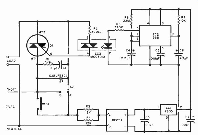
Fig. 1. When power is applied to the circuit by pressing S1, the output
of IC2, through IC3, triggers Q1, which supplies power to the load
(with S2 on "A ") for a time determined by R6 and C4. With
S2 on "B", power is supplied directly to the load.
=====
PARTS LIST
C1--0.1-µF, 200-VDC tubular (272-1053)
C2--0.01-µF, 200-VDC tubular (272-1051)
C3-0.1-µF disc ceramic (272-1069)
C4-2.2-µF tantalum (272-1407)
C5-0.0 HA. disc ceramic (272-1065)
C6-4.7-µF tantalum (272-1409)
C7-100-µF, 10-volt electrolytic (272-1044)
IC1-7805 voltage regulator (276-1770)
IC2-555 timer (276-1723)
IC3 MOC30I0 triac driver ***
Q1-6-A, 200-V
Triac (276-1001)* R1-47-ohm, 1/4-watt resistor
R2-390-ohm, 1/4-watt resistor R3, R4 12,000-ohm, 2-watt resistor
R5-390-ohm, 1/4-watt resistor R6-22-megohm, 1/4-watt resistor *
RECTI I -A, 50-PIV modular bridge rectifier (276-1161)*
S1-Single-pole, normally open pushbutton switch (34-02062V)**
S2-Spdt rocker switch (99-64248V)**
Misc.-Electrical box cover plate, printed circuit board, heat sink, silicone thermal compound, barrier strip (274-657)*, IC sockets (optional), hookup wire, spacers, mounting hardware, etc.
* Radio Shack Part Number
** Lafayette Part Number
*** Motorola Semiconductor component, available from Motorola Distributors
======
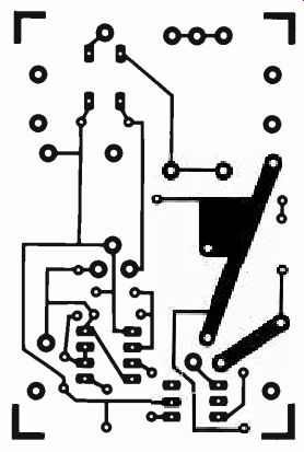
Fig. 2. Actual-size etching and drilling guide for pc board.
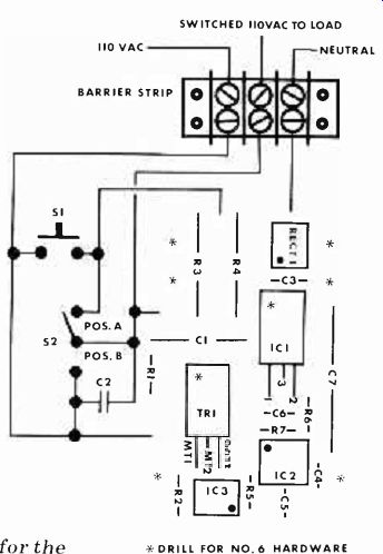
Fig. 3. Parts placement guide for the printed circuit board is shown
at right.
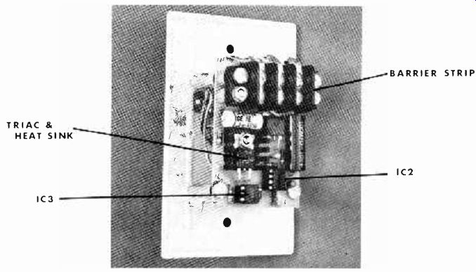
Fig. 4. Photo of the back of the Smart Switch shows how pc board is mounted
on a standard plastic cover plate.
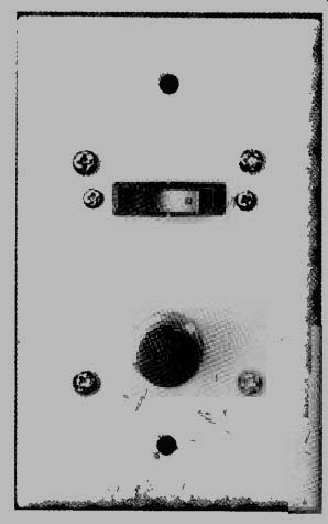
Fig. 5. Completed Smart Switch mounted and ready for use.
The load and the timer circuit will be powered for a period of time determined by values of components R6 and C4.
For the component values shown, this interval is approximately one minute.
Once IC2 has timed out, pin 3 of 1C2 deactivates IC3 and triac Q1. Power is thus removed from the load and the timer circuit.
Placing switch S2 in position "B" bypasses the triac and applies 117 volts ac directly to the load. This feature has been incorporated into the Smart Switch so that the user can manually keep the load powered for an indefinite period of time. If the bypass feature is not desired, switch S2 and capacitor C2 can be eliminated. In that case, however, it will be necessary to connect the MT2 terminal of triac Q1 directly to the junction of S1, R3, and R4 to ensure proper operation of the timer circuit.
Construction. Most of the circuit can be mounted on a single printed circuit board. The etching and drilling and parts placement guides are shown in Figs. 2 and 3; respectively. Triac Q1 must be mounted on a heat sink. Also, be sure to use silicone thermal compound to ensure a good heat transfer. A standard plastic electrical wall-box cover plate should be cut out and drilled to accommodate switches S1 and S2. Capacitor C2 is then mounted directly on the lugs of switch S2.
As shown in Figure 4, a three-terminal barrier strip is mounted on standoffs on the component side of the printed circuit board directly above R3, R4, C3 and RECT1. When soldering capacitor C3 to the pc board, leave the leads long enough so that the body of the capacitor can be bent back to lay flat on top of RECT1. Suitable lengths of hookup wire should be used to interconnect the board and switches S1 and S2.
The completed pc board is then mounted using standoffs on the back side of the plastic cover plate. Be sure to use standoffs that are not too long, as the entire assembly must fit within a standard electrical wall box.
Installation. Before installing the Smart Switch, be sure to turn off the power at the fuse or circuit breaker box.
Remove the existing wall switch and cover plate. Then, using the parts placement diagram shown in Figure 3 as a guide, connect the existing wall-switch wiring to the Smart Switch barrier strip.
You might find that a neutral wire has not been brought into the wall-switch electrical box. If this is the case, wire the neutral terminal of the barrier strip directly to the metal wall box.
Carefully screw the assembled Smart Switch into place and you're ready to start using it. The finished product will look like the prototype shown in Fig. 5.
Use. If you are only going to remain in the room equipped with the Smart Switch for a short period of time, depress S1 as you enter. The lamp controlled by the project will remain on for the period determined by the values of the components in the timing circuit, resistor R6 and capacitor C4. If you intend to remain in the room for an extended period of time, place switch S2 in its "B" position.
Source: (Popular Electronics Electronic Experimenter's Handbook (1982)
Also see:
Precision References for Current & Voltage
Listen To A New World Of Sounds With Ultrasonic Detector
Build a Pink Noise Generator For Audio Testing