By COLLEEN McNEICE and ROGER COTA
Cleans up radio, tape and record signals from any stereo system.
THE "SILENCER" dynamic noise filter described here can eliminate tape hiss, record-surface noise, and atmospheric radio noise. Consequently, it is an ideal add-on device for stereo hi-fi systems. Moreover, it does not require encoding and decoding.
The device is essentially a voltage--controlled low-pass filter whose cutoff or break frequency is continually changing to accommodate program material and shut out any detracting noise. It only filters when noise and hiss are audible, when program material is at a low level or absent. The phenomenon of masking is utilized. That is, high-level signals mask noise that would be objectionable if program material level were low.
When such masking occurs, the whole signal is passed. When there is no masking by program material, however, the filter extends the bandwidth only as far as required by the music. Beyond this, the high-frequency noise is attenuated. The frequency at which the filter begins rolling off to attenuate high-frequency noise is called the "break frequency." About The Circuit. The silencer circuit constantly analyzes incoming signals for amplitude, frequency, and persistence. These factors determine the bandwidth at any instant, as well as how quickly the variable low-pass filter changes. Attack and release times vary with the music, thus eliminating a "pump and wheeze" effect of noise modulation.
The device has a continuously variable threshold control, with front-panel LEDs calibrated to indicate "Low”, "Mid," and "High" break frequencies. The filter's break frequencies vary between 1.5 and 20 kHz with a roll-off slope of 9 dB/octave (maximum). The Silencer is a single-ended stereo device, making it ideal for use with tapes, records, and tuners for playback and record purposes.
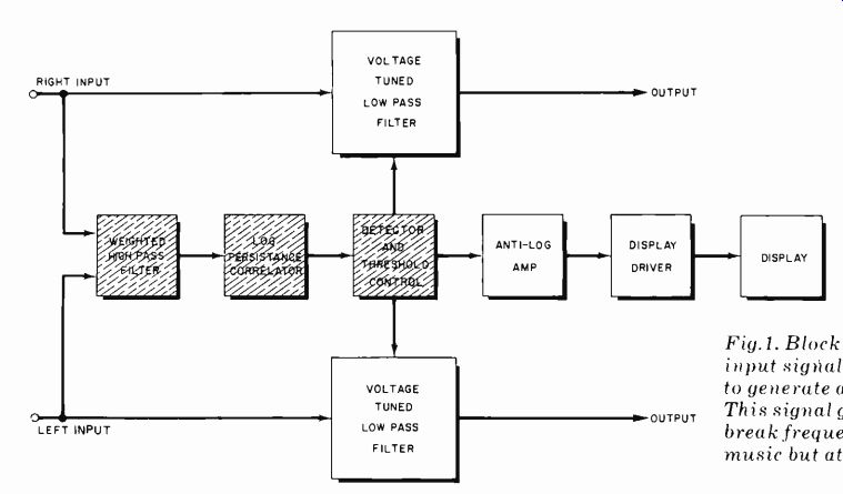
Fig.1. Block diagram shows how input signals are processed to generate
a control signal. This signal governs filter's break frequencies to
pass music but attenuate noise.
======
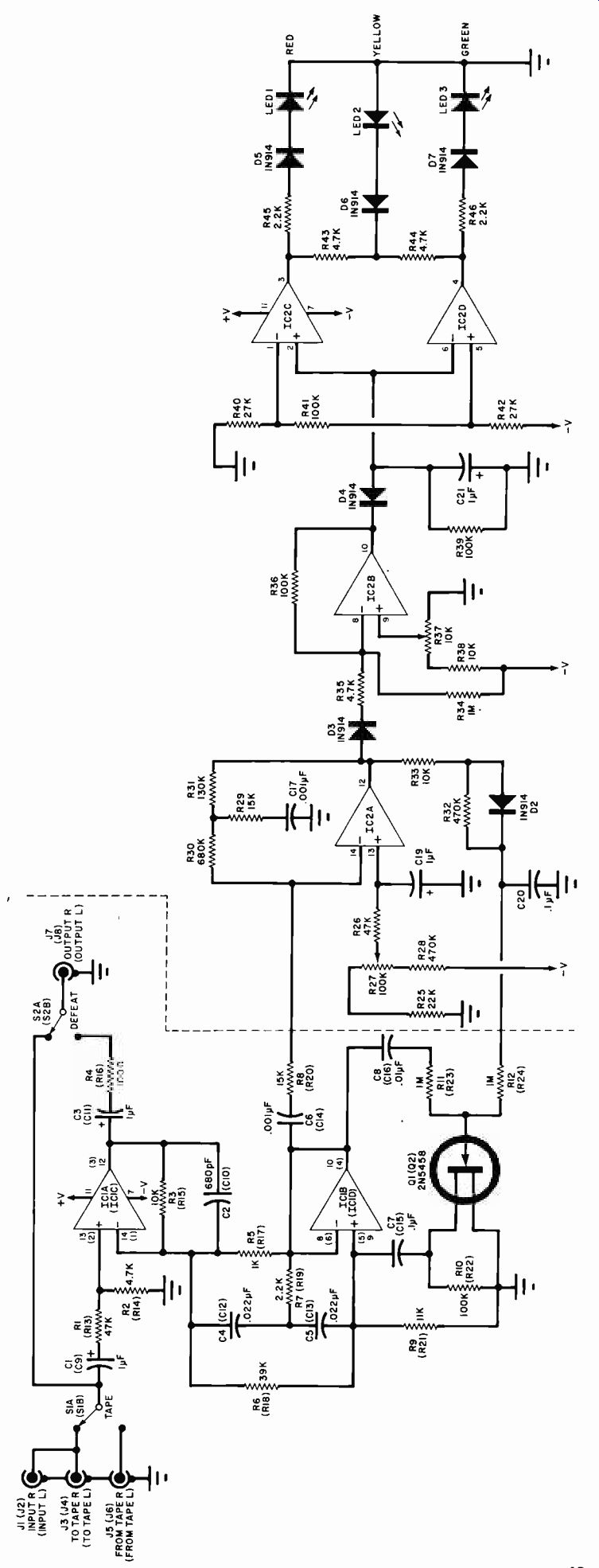
Fig. 2. Schematic diagaram.
PARTS LIST
C1, C3, C9, C11, C21--1-µF 50 -volt axial--lead electrolytic capacitors C2, C10--680-pF disk ceramic capacitors The following are 100-volt Mylar capacitors: C4, C5, C12, C 13-.022-µF C6, C14, C17--.001-µF C7, C15, C20--.1-µF C8, C16-, 01-µF C18, C22, C23, C24--1000-µF 35 -volt radial -lead electrolytic DI -33 -volt Zener diode D2 through D7-1N914 signal diode D8 through D11-IN4002 rectifier F1-1/2-ampere fuse IC1 , IC2-µA4136 quad op amp (Fairchild)
J1-J8 -RCA phono jacks LEDI -Red (Fairchild FLV 110 or equivalent)
LED2-Yellow (Fairchild FLV 410 or equivalent)
LED3-Green (Fairchild FLV 310 or equiv.) Q1, Q2--Matched pair of 2N5458 JFETs.
The following are 1/2-watt, 5% tolerance resistors: R1 , R13, R26-47,000 ohms R2, R14, R35, R43, R44-4700 ohms R3, R15, R33, R38 -10,000 ohms R4, R16--100 ohms R5, R17-1000 ohms R6, R I 8-39,000 ohms R7. R I9, R45, R46-2200 ohms R8, R20, R29-15,000 ohms R9, R21-11,000 ohms R 10, R22, R36, R39, R41-100,000 ohms R11, R12, R23, R24, R34 -I megohm R25-22,000 ohms R28, R32-470,000 ohms R30-680,000 ohms R31-130,000 ohms R40, R42-27,000 ohms Other resistors and controls: R27--100,000 -ohm potentiometer with switch (CTS FR-GC-XM 450 or similar)
R37-10,000 ohm thumbwheel trimpot R47, R48-10 ohms, 1/4 watt, 5% tolerance resistor S1, S2-DPDT switches S3-110-V,2-A switch (part of R27)
T1-22-volt center-tapped, 50 -mA transformer
Misc--AC line cord, knob for threshold pot, buttons for switches, suitable enclosure, hardware, hookup wire, solder, etc.
Note--The following items are available from Video Control, 3314 "H" St., Vancouver, WA 98663 (Tel. 1-206-693-3834): Complete 318 Silencer kit, including 6063 extruded aluminum chassis and hand -finished black walnut end pieces, $159.00.
Also available separately: Etched and drilled circuit board, $16.00; individuality tested and matched 2N5458 FETs. $4.50 Washington state residents please add 50/0 sales tax.
======

Fig. 3. Frequency response of a low-pass filter when its break frequency
is 1500 Hz (top) and 20,000 Hz (bottom).
The unit connects either in the auxiliary mode or in the tape loop of your audio amplifier. On the back panel are IN and OUT jacks for the tape loop; the front panel also has a TAPE monitor button, and a system DEFEAT. The block diagram of Fig. 1 shows the functions of the dynamic noise filter. The voltage-controlled low-pass filter is composed of IC1A and IC1B, as shown in the schematic of Fig. 2. (The components to the left of the dashed line make up one stereo channel; only one is shown in the schematic for clarity.) The gain of op amp IC1A is approximately R3/R5. At low frequencies, the capacitive reactance of capacitors C4 and C5 is very high, making the output of IC1B look like a low impedance source. The gain of IC1A is then: A = R3/R5 = 10,000 ohms / 1000 ohms = 10 At higher frequencies, however, the impedance of C4 and C5 decreases; IC1B generates an output and bootstraps R5. This bootstrapping effect causes R5 to look larger. Therefore, gain A becomes smaller and the filter attenuates the high-frequency energy.
To vary the breakpoint of the filter, FET Q1 has the ability to shunt the signal at the non-inverting input of IC1B to ground. Figure 3A shows the filter with the FET open and the high frequencies attenuated, while 3B illustrates the filter's action with the FET shorting the signal to ground. The control signal applied at the gate of the FET allows the bandwidth of the low-pass filter to be self-adjusting for any frequency. This allows high-frequency signals and subtle harmonics of fundamental bass frequencies to be passed, while unmasked noise is attenuated.
The circuits represented by the shaded blocks of Fig. 1 are the dynamic analytical controls. They automatically judge the program material, adjust the bandwidth to accommodate it, and change the attack and release times to maximize the masking effect and minimize noise modulation. The control signal is applied to the gate of Q1. It's determined by the (1) spectral content, (2) amplitude, and (3) persistence of the incoming signal.
The spectral content is sensed by the high pass weighting filter, a network made up by R8, R29, R30, R31, C6, C17, and IC2A. This network is driven by the output of IC1B, which actually determines the quiescent operating point of the low-pass filter. Amplitude is determined by threshold control, R27, a 100K-ohm front-panel potentiometer.
This pot sets the voltage divider for the positive input to IC2A, and the dc level or IC2A's output. The dc output level determines the quiescent operating point of the FET. The dynamic operation of the FET is adjusted by the ac control signal, allowing it to follow the program material. The ac component of IC2A's output is determined by sensing the signal's amplitude on the output of ICI B. The persistence log amp is formed by R33, D2, and C20. It checks the correlation coefficient of the signal, and adjusts the attack and release time of the low-pass filter to minimize any noise modulation problems. Variable attack and release times allow for the most effective masking of the noise.
The anti-log amplifier IC2B also senses the control voltage output of IC2A. This signal is then rectified and filtered by D4 and C21, and is then used to drive threshold comparators IC2C and IC2D. These amps drive the logic network of D5, D6, and D7, which drives the display. The 10K-ohm trimpot, R37, is used to calibrate the LEDs. The red LED indicates a break frequency of 1.5 kHz, the yellow, a break frequency between 1.5 and 10 kHz, and the green that the filter is opening up above 10 kHz.
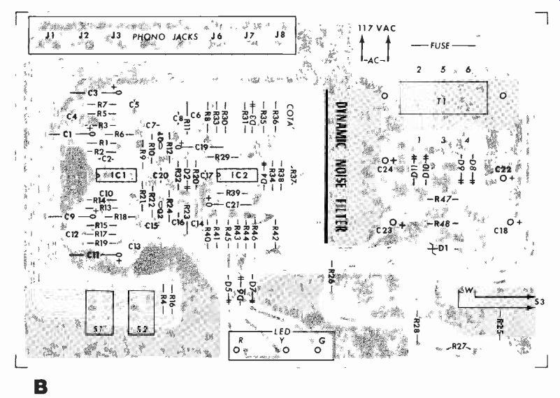
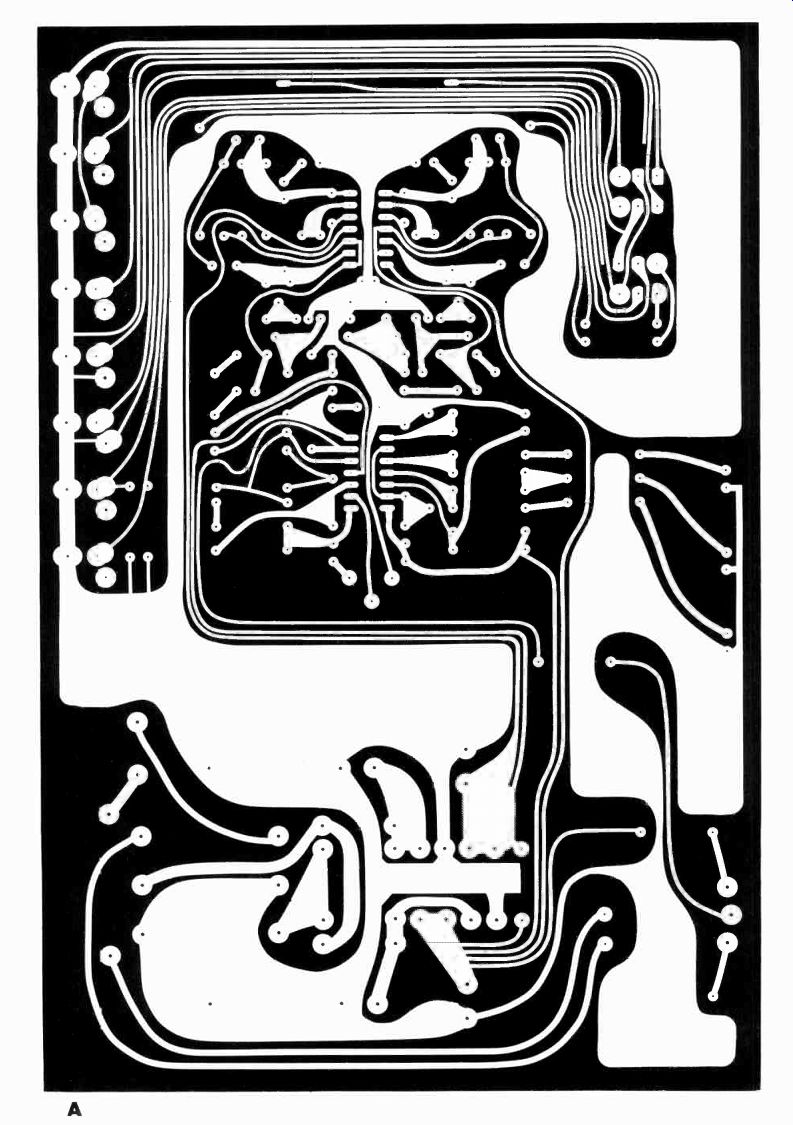
Fig. 4. Actual-size etching and drilling guide for the "Silencer." Board
is shown at (A); parts placement at (B).
----OPERATING SPECIFICATIONS-"SILENCER"---Note: All measurements
made with filter bandwidth open maximum except where specified.
(This is the worst-case condition.)
| Hiss Reduction: Max. Filter Slope: Frequency Response: Minimum Bandwidth: (Filter Closed) Dynamic Range: S/N Ratio: THD: IM Distortion. Rated Output: Max. Output: Input Impedance: Output Impedance: Power requirements: |
15 dB at 10,000 Hz 9 dB/octave 20 to 20,000 Hz -2:0.5 dB 1500 Hz Output noise greater than 100 dB below max. output, 20 to 20,000 Hz Better than 85 dB below 2 V ac output 20 to 20,000 Hz Less than 0.1%, at rated output, 20 to 20,000 Hz. Less than 0.01% at rated output 60/7000 Hz mixed 4:1; typically less than 0.005% 2 V ac into 10,000 ohms 10 V ac into 10,000 ohms 47,000 ohms, single ended 100 ohms 110/120 V, ac 50/60 Hz, 8 W |
------------
------------
Construction. This unit is most easily constructed using a printed-circuit board. Complete etching and drilling guides are shown in Fig.4A, with the component guide shown in Fig. 4B. Proper orientation of parts is very important.
Take careful note of how FETs Q1 and Q2 are mounted as well as op amps, diodes, and electrolytic capacitors. Also observe that the dynamic characteristics of the FETs must be matched. More--over, when choosing op amps, it is important to make sure that the one chosen for the detection circuit, IC2, has an open-loop gain of at least 50 dB at 10 kHz. Op-amps in the parts section were chosen for their excellent noise figures.
The unit is designed to fit into a custom aluminum extrusion, held by the eight screws in the wood ends. Any suitable enclosure will work, however. The circuit board itself measures 6" x 9". The RCA phone jacks, front-panel switches, and threshold pot are circuit--board mounted for ease of construction and minimum noise. LEDs may be circuit-board mounted or attached to your front panel and then wired. If you choose not to use the furnished printed-circuit guides, make sure that the power supply is as far away as possible from the rest of the circuit to eliminate stray hum.
Calibration. Calibration should be done before you fully enclose the unit.
To calibrate, connect the noise filter into your amplifier's or receiver's auxiliary or tape input. Find a low-level noise source--an erased magnetic tape would be ideal. If you don't have tape facilities you may use the inside groove of an LP record. Increase the amplifier's gain so you can hear the noise very well.
Start with the Silencer's threshold pot turned fully counter-clockwise and slowly turn the control knob clockwise.
You will hear the noise change character and become more objectionable. Return to the position where the noise-content change just begins (listen several times so you will be able to identify this point). With the threshold knob in this position, adjust R37, the thumbwheel trimpot, so that the red LED lights. You should adjust the pot so that it is at the point where only a slight adjustment will cause the yellow LED to light.
In conclusion, this easy-to-build noise-reduction system will be a helpful and versatile addition to-any stereo hi-fi system, cleaning up signals from any source.
Source: (Popular Electronics Electronic Experimenter's Handbook (1982)
Also see:
Precision References for Current & Voltage
Listen To A New World Of Sounds With Ultrasonic Detector