BY ANTHONY J. CARISTI
During the heating season, you can feel warmer at 65° F, if you humidify the heated air.
IN THESE days of high energy costs, each of us must pitch in to help reduce energy consumption. In particular, if you are a home owner, you can help simply by turning down the thermostat. At the same time, however, you will want to turn up your "comfort" level. One way to do this is to increase the relative humidity in your home by modernizing the humidification system in your warm-air furnace. The Solid-State Humidity Control described here does just that, economically and reliably.
This automatic humidity control is an easy-to-build, low-cost device that couples to a solenoid-controlled water valve and special humidifier spray nozzle.
(Spray nozzles of various water capacities are readily available at many hardware and plumbing-supply outlets at reasonable cost.) To reduce parts cost, you can use a solenoid valve recovered from an old washing machine, if available. The spray nozzle itself mounts anywhere in the direct stream of the heated air so that the fine water mist turns to vapor.
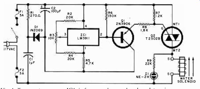
Fig. 1. Temperature sensor IC1, in furnace plenum chamber, determines
when solenoid operates to spray fine water mist into chamber.
========
PARTS LIST
C11-µF, 200-V nonpolarized capacitor
C2-100-µF, 25-V tantalum capacitor
D1-1N2069 or similar rectifier
F1 ,F2-3-ampere slow-blow fuse (MDL-3 or equivalent)
I1--NE-2H neon lamp
IC1--LM3911N temperature-controller (National)
Q1-2N3906 or similar transistor
Q2-T2302B triac (RCA)
The following resistors are 1/4-W, 10%. unless otherwise specified:
R1-270-ohm. 2-watt, 10% resistor
R2, R4--20,000 ohms metal film (see text)
R3--10,0(X)-ohm subminiature trimmer
R5-4700 ohms
R6-150.000 ohms
R7-1200 ohms
R8-1800 ohms
R9-22,(X)0 ohms
S1--Spst switch (optional)
Misc.-Printed-circuit board: fuse holders for F1 and F2; 120-volt AC water solenoid (W.W. Grainger No. 6X230 or similar); spray nozzle (see Note below); 4-conductor (color-coded) cable; hookup wire; etc.
Note: The following items are available from A. Caristi, 69 White Pond Rd., Waldwick, NJ, 07463: printed circuit board for $3.60; IC1 for $3.00; Q2 for $3.00; spray nozzle (specify A37 for 0.37 gal/hr or A-50 for 0.50 gal/hr) for $6.75. Add 50 cents for postage per order.
=========
Why Humidify? All heating systems, whether warm-air, hot-water, or steam, should have some form of humidification to promote a healthy environment for you, your family, pets, furnishings, plants, etc. This is especially important during the winter months when the air inside of the home is closed off from the outside air and is heated.
When air is heated, its relative humidity decreases from a healthy 30-50% to as low as an arid 10-20%. The latter is far too low for comfort. It irritates sensitive membranes (which accounts for all those sore throats you get during the winter); is a poor conductor of electricity (hence, the build-up of annoying static--electricity charges on your body when you cross a rug); and makes temperatures in the 500 to 70° F range appear to be colder than they really are.
By raising the humidity level in the air in your home during the winter months, you can alleviate many of these problems. In terms of saving energy (fuel), you can reduce your thermostat setting while maintaining a relative humidity of 30% to 50% and feel warmer at 66° to 70° F than you would at 75° in arid air.
Circuit Operation. The heart of the humidity controller is a special integrated circuit, IC1. This four-terminal LM3911 has an entire temperature-control system on a single chip. Included in this IC are a temperature sensor, stable voltage reference, and operational amplifier. As shown in Fig. 1, the internal op amp is wired as a comparator with external resistors so that the pin-2 output switches voltage as the temperature of the IC's case traverses the set-point determined by the reference voltage on pin 3. Since the IC has a built-in 6.8-volt reference supply, the temperature switch-point of the controller is held stable regardless of power-line voltage.
The output current from IC1 is insufficient to drive the gate of triac Q2. Therefore, Q1 is used to amplify this current to a sufficient level.
When the temperature of IC1 drops below the set-point, the voltage at pin 3 cuts off Q1. Conversely, as the temperature rises above the set-point, IC1's output switches negative and sends Q1 into conduction. This, in turn, applies sufficient current to the gate of Q2 to cause the triac to trigger on and energize the water solenoid. Neon lamp II, connected across the solenoid (with dropping resistor R9), provides visual indication that the solenoid has been energized and the water is on.
By physically locating IC1 in the warm-air stream of the furnace, we can ensure that the water solenoid will be energized only when the temperature of the heated air is sufficient to vaporize the mist from the spray head. When the burner shuts off and the air cools, the spray is automatically terminated. Potentiometer R3 in the input circuit of IC1 allows you to select warmer or cooler switching temperatures, permitting you to adjust duty cycle of the spray and, thus, the degree of humidification.
DC power for IC1 and Q1 is provided by R1, C1, D1, and C2, with R1 and C1 forming a voltage-divider network. Since C1 is purely reactive, it dissipates no power and remains cool. This makes it possible to develop a relatively low voltage across R1 without need for a power transformer or high-wattage resistor.
Current through D1 charges C2 to about 20 volts. Fuses F1 and F2 protect the circuit against excessive damage in the event of component failure. As either side of the circuit can be connected to the "hot" leg of the power line, both sides are fused.
Construction. The circuit is best assembled on a printed-circuit board, etching-and-drilling and components-placement guides for which are shown in Fig. 2. When laying out the board for etching, be sure to maintain the heavy conductor traces where indicated.
Wire the board as shown, taking care to properly orient D1, C2, Q1, and Q2.
Be sure to use a nonpolarized capacitor for C1.
Metal-film resistors are specified for R2 and R4 in the Parts List to maintain greatest temperature set-point stability.
If you substitute 10% composition resistors, you can use 18,000 ohms instead of the specified 20,000 ohms.
Note that IC1 mounts off the board, inside the heated-air chamber (plenum) of your furnace, where it will be able to sense burner operation. Connection between IC1 and the board is accomplished with a four-conductor, preferably color-coded, cable. Pay strict attention to pin connections when wiring IC1 to the board via its cable, referring back to Fig. 1 as necessary. (The length of the interconnecting cable is not critical.) When mounting IC1 in the plenum, make absolutely certain its terminals are insulated from all metal parts in the furnace, since the IC is electrically connected to a circuit that does not have an isolation transformer. Should the IC touch any metal part of the furnace, the resulting short circuit will destroy the IC. Also, do not locate IC1 where it will come into contact with the water supply.
The water solenoid valve terminals connect to the pc board at the two points labeled with an S. Use at least 20--gauge wire for the connections. Power input to the circuit, labeled AC on the board, can be made via a conventional line cord and plug. You can install an optional power switch in series with the ac line, if desired.
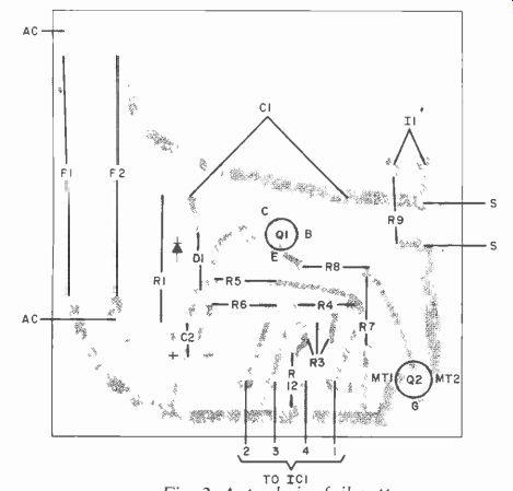
Fig. 2. Actual-size foil pattern for pc hoard is at right; component
installation above. Note that IC1 is not on the hoard. When mounting
board, make sure it is isolated from ground.
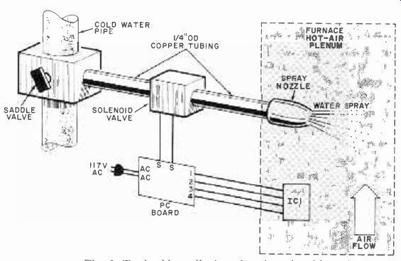
Fig. 3. Typical installation showing plumbing. An optional power switch
can he connected to the ac line.
Typical installation of the system is illustrated in Fig. 3. The water connection between supply and spray nozzle can be made via 1/4 " (6.4-mm) copper tubing and plumbing fittings as required. Mount the spray nozzle to the wall of the plenum chamber so that it sprays into the heated section of the warm-air chamber.
Do not place it in the cold-air return. To do so will cause improper operation and possible damage to your furnace.
Checkout and Use. Before installing the control system, check for correct circuit operation. You do not need the water-supply connection for this check.
First, make certain that IC1 is fully insulated from all metal objects and your person. Then connect the solenoid terminals to points S on the board. Rotate R3 over its range. At some point, you should hear the solenoid click and see the neon lamp light simultaneously. This setting will be close to room temperature. Adjust R3 so that I1 just extinguishes to obtain an approximate setting for the potentiometer. This done, disconnect the project from the ac line and install the pc board permanently.
Install the spray nozzle in the plenum. Refer to the Parts List for specifications on two sizes of spray nozzles. Use part No. A-37 for smaller or No. A-50 for larger homes.
Final adjustment of R3 can be made by placing the furnace in operation and setting the pot to operate the solenoid just after the furnace blower comes on. This will provide maximum humidification for your heating system. If you require less humidification, readjust R3.
In Closing. If you wish to conserve energy and/or reduce your heating costs while maintaining a comfortable living environment, simply modernize your humidifier system with the automatic controller described here.
Source: (Popular Electronics Electronic Experimenter's Handbook (1982)
Also see:
Precision References for Current & Voltage
Listen To A New World Of Sounds With Ultrasonic Detector