AMAZON multi-meters discounts AMAZON oscilloscope discounts
Introduction
Any length of wire will act as an antenna (or aerial) but, to get the best results from a transceiver or receiver, an aerial tuning unit (ATU) is required. This matches the impedance of your aerial to the impedance at the aerial socket of your radio. Impedance is like resistance, and is measured in ohms, but it is used for alternating currents, and hence is common in audio and RF engineering. Most receivers have an impedance at the aerial socket of about 50 ohms; aerial impedance, on the other hand, can be anywhere between 20 ohm to over 1000 ohm, depending on its length and its height above ground.
Fortunately, you don't need to be able to calculate your aerial's impedance; all you need is a device that will perform the matching operation for aerials with a large range of impedances, and this is exactly what is described here! The subject of matching is a complex one, but all you need to know is that most signals will become clearer, and that there will be less noise and interference. Stations will become louder, so you will probably be able to reduce the setting of your RF gain control (always a good thing to do).
This design of ATU covers all amateur and broadcast bands from 10m (28MHz) to 80m (3.5MHz), and is very easy to build. The circuit is shown in Figure 1.
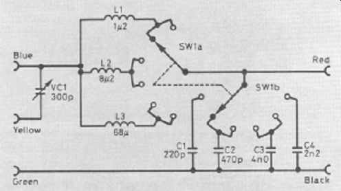
Figure 1 Circuit diagram of the Antenna Tuning Unit, showing the use of a
2-pole, 6-way rotary switch to select inductors (L) and capacitors (C)
Construction
1. Firstly, you will need a simple plastic case in which to house the ATU.
The size should be approximately 85 × 145 × 50mm.
2. Start by drilling two 10.5mm holes in the front of the case; these are for the 6-way switch and the tuning capacitor.
3. Drill three 8mm diameter holes in the left-hand side of the box, for the three sockets, colored blue, yellow and green.
4. On the right-hand side of the box, drill two 8mm diameter holes for the red and black sockets.
5. Now, fit the 6-way switch (SW1), the tuning capacitor (VC1), and all the sockets to the case. Check that the vanes of the capacitor rotate smoothly when the shaft is turned.
6. Wire up the inductors (coils). Figure 1 and the wiring diagram of Figure 2, will help with this. As you can see, each one side of each coil is connected to two switch connections, the other end going to VC1.
7. Solder in the fixed capacitors. One end of each goes directly to the ground socket (black), and the other end goes to the switch.
8. Solder a wire between the green and black sockets. The output from the ATU comes from the red socket, and this is connected to the two tags in the center of the switch, as Figure. 2 shows clearly.
9. Finally, connect the blue and yellow sockets to the tuning capacitor, and the ATU construction is complete.
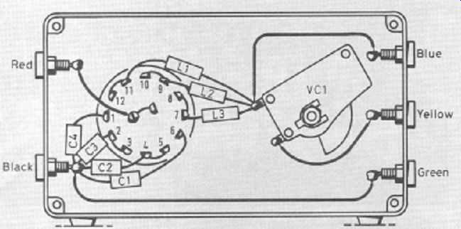
Figure 2 The internal view of the case shows the main tuning capacitor, VC1.
This is a solid dielectric type, which has adjustable brass plates
In practice …
Figures 3 and 4 show two different ways of connecting your aerial to your ATU. In each case you will need to select each switch position in turn, and rotate the tuning capacitor through its full range while listening to a station.
You should find that one switch position enables VC1 to produce a peak in the signal strength in the loudspeaker. At this point, your aerial and receiver are said to be matched. Stations in the same band will probably peak with VC1 at the same setting of SW1, but different bands will almost certainly require different positions of SW1.
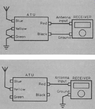
Figure 3: You may find that parallel tuning gives best results with your antenna;
Figure 4: In other cases, series tuning could be the most effective arrangement
Parts list:
Capacitors (all rated at 16V or more):
C1 220 picofarads (pF) polystyrene
C2 470 picofarads (pF) polystyrene
C3 1000 picofarads (pF) or 1 nanofarad (nF) polystyrene
C4 2200 picofarads (pF) or 2.2 nanofarads (nF) polystyrene
Inductors:
L1 1.2 microhenries (uH)
L2 8.2 microhenries (uH)
L3 68 microhenries (uH)
Switch
SW1 2-pole 6-way rotary
Sockets:
4mm type, one each of red, black, yellow, blue, green Additional items
Plastic or metal case, e.g. Maplin type YU54
Two large knobs for SW1 and VC1