AMAZON multi-meters discounts AMAZON oscilloscope discounts
Introduction
No apologies for yet another design of short-wave radio. This is the beauty of our hobby -- there is always something new to try. Not all circuits operate in the same way; not all circuits work equally well; sometimes a simple design suits the operator better than a complicated design. So here is another one for your consideration; it's a good project for a novice, and a good one-evening project for someone more experienced.
A basic description
Figure 1 gives the block diagram of the receiver, which employs a regenerative detector , one of the earliest techniques by which excellent selectivity (the ability to separate two stations very close in frequency) could be combined with good sensitivity (the ability to pick up very weak stations) using a very simple circuit. The receiver falls into the category known as tuned radio frequency (TRF), meaning that the whole circuit (prior to the extraction of the modulation from the carrier) operates at the incoming radio frequency. In other words, it is not a superhet.
As you can see, the regenerative detector has what is called a feedback loop, which feeds a small amount of the output signal back to the input. You have heard the effects of feedback with a public address system, when the microphone gain is too great -- everything becomes very loud and then bursts into a deafening squeal! This is exactly what the feedback does here, except that it is carefully controlled, thus providing both gain and selectivity. The resulting audio is then amplified for use with headphones.
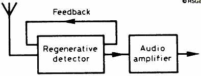
Figure 1 Just two simple stages make up the circuit
The circuit The circuit of Figure 2 shows the complete system. TR1 is an untuned field effect transistor (FET) stage, and is used to match the aerial to the next stage. Occasionally, a regenerative detector produces unwanted signals, and TR1 also prevents them from reaching the aerial and being transmitted! The smaller of the two windings on T1 (the primary winding) will match a low impedance aerial, the capacitor input matching a high-impedance aerial.
Ignore TR2 for the moment -- the next stage in the signal path is TR3, the detector, using another FET. The tuned circuit is formed by T2, VC1 and VC2 (remember TR1 is untuned). The primary winding on T2 taking the output from TR1. The reason for having two variable tuning capacitors, one large, the other small, is that the large capacitor is the main tuning capacitor, while the small one is used as a bandspread control (for very fine tuning). The tuned signals are then detected (converted to audio frequencies) by TR3.
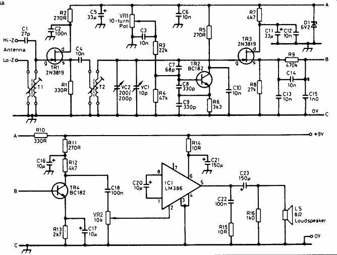
Figure 2 The circuit diagram showing the 10-turn potentiometer VR1. This
is the regeneration control for the circuit
TR2 is a Q-multiplier stage. It is a Colpitts-type oscillator which uses C8 and C9 to give feedback and produce the oscillation. C7 couples the tuned circuit (and the input to TR3) to TR2. The tuned circuit thus controls the frequency of oscillation of TR2 and the signal passed on to TR3.
The secret of the ease of operation of this receiver is VR2, a 10-turn potentiometer (or helipot). The resistance wire is wound in the form of a helix, giving a much greater wire length than in a normal potentiometer, and the shaft must be turned ten times to cover the whole length. Helipots are very useful when very fine adjustments have to be made. Here, VR2 sets the regeneration (or reaction) level, depending on the type of signal you are receiving, as will be discussed in Part 2.
TR4 provides the first stage of audio amplification and, after the volume control, VR2, the audio amplifier integrated circuit, IC1, will drive a small loudspeaker or headphones.
In Part 2, the construction will be discussed, together with the choice of aerial, the parts list, and advice on using the receiver.