AMAZON multi-meters discounts AMAZON oscilloscope discounts
Introduction
It is always valuable to have a means of measuring capacitors amongst your test gear. Universal LCR bridges (i.e. systems that can measure inductance, capacitance and resistance) can be found at most rallies, and you can work your way up to owning one of these. In the meantime, a piece of home made equipment gives you experience as well as resulting in a useful measuring instrument.
The circuit described here is called a capacitance bridge, because it balances the effects of one resistor/capacitor pair against another; if one capacitor has an unknown value, then the other can be calculated. The basic bridge circuit is shown in Figure 1. To avoid having calculations to perform, this instrument will be calibrated by using capacitors of known values. The bridge is a useful way of performing measurements, because a knob is turned until there is a null in the signal from an earpiece or loudspeaker.
The ear is very precise in being able to perceive nulls, which makes the bridge easy to use and reasonably accurate. At the null, the bridge is said to be balanced.
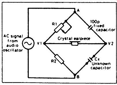
Figure 1 Simplified circuit of a capacitance bridge. R1 is adjusted for minimum
sound
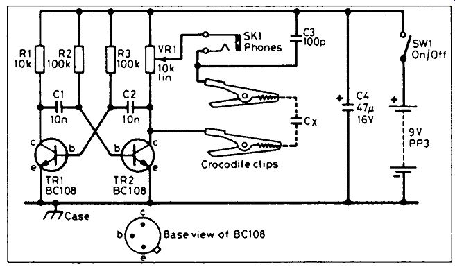
Figure 2 Transistors TR1 and TR2 give an audio signal which is adjusted by
variable resistor RV1
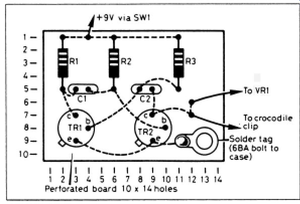
Figure 3--Components are soldered together on a small prototype board
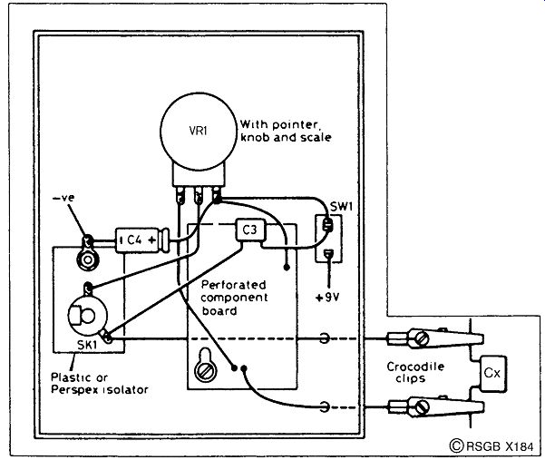
Figure 4--Layout of the parts inside an aluminum box. The earpiece socket
is insulated from the case
How does it work?
Figure 2 is the circuit diagram for this capacitance bridge. Transistors TR1 and TR2 form an oscillator. This is the audio oscillator shown in Figure 1, and produces an alternating voltage which is fed to the bridge. RV1 (in the collector lead of TR2) replaces both R1 and R2 in Figure 1 -- that part of RV1 above the wiper represents R1, while that part below the wiper represents R2. The voltage on one side of the earpiece is determined by the ratio of these values, and is adjusted by rotating RV1. The voltage on the other side of the earpiece is determined by the ratio of C3 to Cx, where Cx is the unknown-valued capacitor. When these two voltages are the same, the bridge is balanced and there is no current through the earpiece.
Figure 3 shows the layout of the components on the matrix board of the prototype. It measures 10 holes by 14 holes, and is of the plain type, i.e. no copper strips. All earth connections are taken to a single solder tag. When mounting the board inside a metal box, a long screw is used with extra nuts, to earth the board to the case while providing a stand-off, thus preventing any unwanted short-circuits between the board connections and the case. Be aware that a crystal earpiece must be used; low-impedance headphones of the Walkman type are not satisfactory. Solder two flying leads as shown in Figure 4, about 15 cm long, terminated in small crocodile clips for attaching to the unknown capacitor.
Calibration
After checking the circuit carefully, attach the battery and switch on; a buzzing noise should be heard in the earpiece. This is the first sign that everything should be OK. If there is no buzz, switch off and recheck the connections.
You will now need a range of close-tolerance (1%) silver-mica capacitors covering the range 10 to 1000 picofarads (pF). Arrange the capacitors in ascending order and connect them to your bridge in sequence. After having prepared a neat piece of card or paper mounted behind the knob on the front panel, mark the dial at the positions of the nulls for all the capacitors.
You have now calibrated your capacitance bridge. If you are more likely to want to measure larger capacitors, replace C3 by a 1 nanofarad (nF) capacitor, and the bridge will measure up to 10 nF approximately.

Parts list
Resistors: all 0.25 watt, 5% tolerance
R1 10 kilohms
R2, R3 100 kilohms
RV1 10 kilohms linear
Capacitors
C1, C2 10 nanofarads (nF) ceramic
C3 100 picofarads (pF) silver mica or polystyrene
C4 47 microfarads (uF) 16V electrolytic
Semiconductors
TR1, TR2 BC108 npn
Additional items
SW1 SPST on/off switch
Battery connector, PP3 type
Earpiece, crystal type
SK1 3.5mm jack socket for earpiece
Battery, 9V PP3
Matrix board, approx. 10 holes by 14 holes
Aluminum case, approx. 10 × 8 × 5cm