AMAZON multi-meters discounts AMAZON oscilloscope discounts
Introduction
Many readers will know that, although they have a short-wave radio which covers at least one of the amateur bands (e.g. 7MHz or 14MHz), they are unable to listen to SSB or Morse signals. This is because the receiver lacks a Beat-Frequency Oscillator (BFO). We need the 'carrier' frequency of a BFO to replace the carrier that has been removed from the signal at the transmitter. When listening to Morse signals, the BFO signal 'beats' with the incoming signal to produce a note in the loudspeaker. If you are a musician, you will be familiar with the method of using 'beats' to tune one musical instrument from another; in the BFO, the beat frequency produced is the tone signal you hear.
In the more complex amateur radio receiver, a BFO is incorporated as part of the whole system. In our model, it is an external circuit that sits alongside your radio. The circuit diagram is shown in Figure 1.
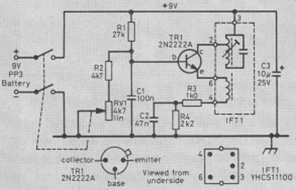
Figure 1 Circuit diagram of the BFO.
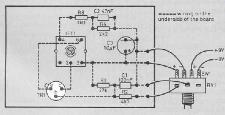
Figure 2 Matrix board layout shown from the component side. Adjust IFT1 carefully
for the best results.
Construction
Built on a small piece of matrix board about 80 × 50mm, the circuit can be fitted inside a small plastic box. For once, we don't want to screen the circuit to prevent it interfering with other equipment; we want it to interact with our receiver! This is why we use a plastic box. Electronic Components supply a suitable box, complete with the matrix board to fit inside.
Look at Figure 2 carefully before you start to build the circuit, so that you can position the components correctly. Firstly, inspect the intermediate frequency (IF) transformer, IFT1, and remove its metal screening can very carefully. Again, this is to allow some signal to escape from our circuit and enter our radio. Having done this, solder the components, using the matrix board as a support. Underneath the board, the components are linked by single-conductor, insulated wire. Take particular care with the polarity of the electrolytic capacitor, C3, and the connections to the transistor, TR1 (see Figure 1).
The variable resistor, VR1, has a switch mounted behind the control itself, and the insulated leads to it from the battery should be about 10 cm long.
Connect these before fitting VR1 into the case, so that the BFO can be calibrated (adjusted) correctly.
Calibration
After a final check that all the components have been fitted and soldered correctly, connect the battery, switch on, and hold the transistor between your fingers, to check that it is not getting hot. Place the circuit close to your receiver, and set RV1 to mid-position. Tune your receiver to find an amateur SSB transmission; the frequencies listed below will help you in knowing where to look. It may sound very strange, but don't worry. Slowly turn the core of IFT1 with a small, non-metallic screwdriver or with the correct 'trimming tool'. The core into which the blade fits is very fragile, so attempt this process with care. When the speech sounds as natural as you can get it, leave the core at this position, and use RV1 to make the speech sound natural.
Using the BFO
For best results, you may have to move the BFO nearer or further away from your radio. At the lower end of most bands (for instance just above 7.000MHz or 14.000MHz) you should be able to resolve Morse code (CW) signals. If you find that the BFO signal is a little weak, solder a 15 cm length of insulated wire to pin 2 of IFT1, and place it alongside your radio.
This should improve signal intelligibility. When you are happy with the performance, switch off, drill a 10.5mm hole in the box and fit RV1, followed by the matrix board assembly. Screw the base to the box, fit the knob, and the BFO is complete!
Where to listen:
Band Frequencies (MHz)
15m 21.000-21.450
17m 18.068-18.168
20m 14.000-14.350
30m 10.100-10.150
40m 7.000-7.100
80m 3.500-3.800
Parts list
Resistors: all 0.25 watt, 5% tolerance
R1 27 kilohms (kΩ)
R2 4.7 kilohms (kΩ)
R3 1 kilohm (kΩ)
R4 2.2 kilohms (kΩ)
VR1 4.7 kilohms (kΩ), linear, with DPST switch
Capacitors:
C1 100 nanofarads (nF) or 0.1 microfarad (uF), ceramic
C2 47 nanofarads (nF) or 0.047 microfarad (uF), ceramic
C3 10 microfarads (ΩF), 25V radial, electrolytic
Additional items:
TR1 2N2222A npn
IFT1 Toko type YHCS11100
Box plastic, approximate size 100 × 70 × 45mm
Board matrix, to fit inside the box
Connector for PP3 battery
Knob for RV1