AMAZON multi-meters discounts AMAZON oscilloscope discounts
1. The Function of a Filter
Like many technical words coined initially to describe a specialized function, the word filter has broadened in scope with the passing years. Despite the many phases of electricity and electronics in which it occurs, however, the word has retained its original core meaning. Any filter, whether in a power supply, a high-fidelity amplifier, a radiotelephone transmitter, a keying system, an antenna, or a transmission line, is a frequency-sensitive device discriminating against certain frequencies in favor of others. In most filters discrimination is accomplished by weakening a preselected range of frequencies while others are untouched, causing the system response curve to undergo a reduction in amplitude for the filtered range.
This does not lead to a depression in the response curve (Fig. 1A) if the plot of amplitude vs frequency possesses a non-linearity in the form of a raised bump, (Fig. 1B). A filter of this type may be employed to straighten out the curve.
Certain filter arrangements may produce frequency discrimination by boosting rather than weakening ·a selected group or range of frequencies. Here again, the result of such peaking may raise a bump in the response curve which was not there initially (Fig. 2A) , or may straighten out a curve that has an undesirable depression in it (Fig. 2B) .
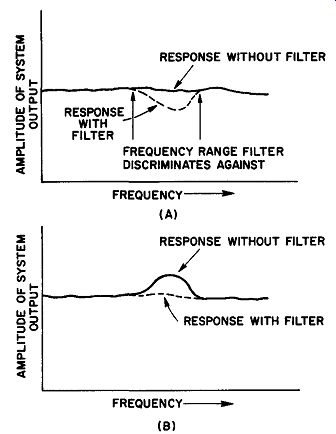
Fig. 1. (A) If the system output is uniform or linear, one type of filter
might cause a notch to appear, as in this case. (B) The same filter might be
used to straighten the response curve if it originally contained a non-linearity,
as here.
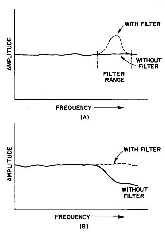
Fig. 2. (A) A peaking filter will produce a bump in an otherwise linear response
curve. (B) The action of the same filter on a non-linear curve having a corresponding
depression.
In discussing the action of any filter network or group of filter components working together to consummate the desired frequency discrimination, we must consider several factors. Broadly outlined, these are:
(1) The range of frequencies covered. If the filter is designed to weaken, or attenuate, a relatively large range, it may be generally described as a wide-band filter. A filter acting upon a small range of frequencies is a narrow-band filter. (Fig. 3A and B.) (2) The nominal center frequency of the filter -- the frequency discrimination position in the frequency spectrum. For example, audio filters are effective in the audio range, i-f filters in the inter mediate frequency range, and so on. Center frequencies, then, can only be given for filters like Fig. 3A and B, and not C and D.
(3) We usually specify the frequency at which filter action begins, for filters producing the attenuation of Fig. 3C or D. The starting point must be defined exactly to be precise about the point at which any action starts. Let us give a specific example. Suppose a certain audio amplifier has the response curve of Fig. 4. (The drawing has been idealized to make the definition more clear-cut). Calling its mid-range voltage gain arbitrarily 0 db, we see that the gain falls off at both the low and high ends of the audio band. The -3 db point has been conventionally selected as the termination of the flat part of the curve; in other words, this amplifier (without filtering, is said to be flat from 20 hz to 20,000 hz, even though the absolutely level part of the curve does not extend below 300 hz nor above 8000 hz. The frequency f1 is, therefore, termed the lower cutoff frequency of the amplifier and f2 the upper cutoff frequency.
Assume now that a filter is introduced to attenuate the response at the high end of the band. Using the same -3 db level as for the amplifier cutoff frequencies, we say that the cutoff frequency of the filter (symbolized f0 ) is that frequency at which the amplifier gain is brought down 3 db below the mid-range gain. Hence, the starting point for filter action, or f0 in this example, is 8200 hz.
(4) Filters are sometimes classified in terms of the slope of their characteristic below f11. The curve of Fig. 3C might be termed gradual cutoff to distinguish it from that of 3D, which is a much sharper cutoff type of curve.
2. Types of Filters -- Filter Vocabulary
The descriptive terms used in the sections that follow, although not solely associated with filters have common and specific technical meanings. It would be helpful to know the basic definitions of the ...
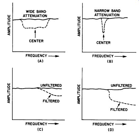
Fig. 3. (A) A wide-band filter attenuates a broad range of frequencies on
either side of Its center frequency. (B) A narrow-band filter attenuates a
small range an either side of the center. (C) This filtering action Is gradual.
(D) A sharp cutoff filter in action.
.... more important of these terms. Their exact significance will be fully treated in context.
Transmission: As specifically applied to filters, transmission implies the act of carrying a frequency or a range of frequencies from the input to the output of the filter without weakening it significantly.
The -3 db point, as previously discussed, is generally taken as the point at which significant weakening begins.
Attenuation: This term is the opposite of transmission. When a signal is reduced in amplitude to the extent of a 3 db drop, as compared with its original value, attenuation is said to begin. Any further diminution of amplitude may be described in terms of attenuation in db.
Rejection: A specific frequency or range of frequencies is said to be rejected if it has been attenuated sufficiently to meet predetermined specifications. For instance, if a given radio signal interfering with a desired frequency is reduced to a value which makes it inaudible in a specific receiver, it is considered rejected.
Pass band: A range of frequencies passing through a filter without undergoing attenuation. Figure 4 can be used to illustrate. The pass band of this amplifier without filter extends from 20-20,000 hz; with filter, the pass band covers the range from 20-8200 hz. Hence, attenuation occurs below 20 hz and above 8200 hz with filter action. Extrapolating the curve downward enables us to say that all frequencies above approximately 10,000 hz are rejected. We may also define the filtered amplifier response by saying that all frequencies between 20 and 8200 hz are transmitted.
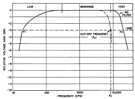
Fig. 4. Idealized response of on audio amplifier with and without filtering.
The cutoff frequency of the filter (fa) Is 8200 hz, or the frequency at which
the gain is 3 db below the mid-range gain.
Low-Pass Filter: A low-pass filter attenuates all frequencies above a selected frequency. The selected frequency is the cutoff frequency of the filter (fa) and marks the point above which all frequencies are attenuated. (Fig. 5A.) High-Pass Filter: A high-pass filter attenuates all frequencies below a selected frequency. The latter marks the cutoff frequency of the filter and designates the point above which all frequencies are transmitted. (Fig. 5B.) Bandpass Filter: A bandpass filter transmits a range of frequencies.
All frequencies below the lower cutoff (f1) and all frequencies above the upper cutoff (f2) are attenuated. (Fig. 5C.) Sand-Elimination Filter: A band-elimination filter attenuates a range of frequencies. The lower cutoff frequency and the upper cutoff frequency determine the points beyond which transmission begins in both directions (Fig. 5D) . Untuned Filter: An untuned filter, may be made up of resistive and capacitive components, or of inductive and capacitive components, or all three. Such a filter does not resonate at any given frequency; it accomplishes the desired filtering action by means of high and low impedances properly placed with relation to the source and the load.
Tuned (or Resonant) Filter: A tuned filter operates by virtue of either a series or parallel resonant circuit in the transmission system. Such resonant circuits may appear in series with the leads from source to load, or in shunt with them. Tuned filters usually (but not always) are designed to have very narrow pass or rejection bands as compared with untuned filters.
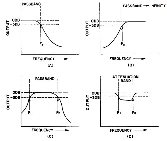
Fig. 5. (A) Low-pass filter. (B) High-pass filter. (C) Bandpass filter. (D)
Band elimination filter.