AMAZON multi-meters discounts AMAZON oscilloscope discounts
3. General Characteristics of Power Supply Filters
Fig. 6. Full-wave and half wave rectified amplitude variations are equal In
corresponding systems, but the time between successive pulses in a half-wave
arrangement is much greater.
The output voltage from a rectifier device has a pulsating wave form which must be smoothed to prevent the supply from introducing hum into the equipment it supplies with power. Although the voltage amplitude variations from a full-wave system are just as severe as those obtained by half-wave rectification, full-wave output is easier to filter because the gaps that require filling in are much smaller (Fig. 6) . A practical filter network generally contains a combination of capacitors and resistors, or capacitors and inductors. In some cases, all three circuit elements are found in the same filter system. Generally L-C circuits are used when the current flowing through the load is fairly large and where good voltage regulation is demanded.
In power supplies provided for small, constant-current electronic devices, it is often possible to eliminate the inductor entirely, and to use a resistor in its place. Such networks are known as R-C filters and may be found in small table-top radios, portable a-c phonographs, and similar low-power devices.
The design and construction of a practical power supply requires consideration of:
(a) The maximum tolerable hum or ripple content of the d-c output.
(b) The desired voltage regulation.
(c) The maximum load current anticipated.
(d) The output voltage desired.
That is, whether the designer wishes to make use of the peak value of pulsating voltage fed to the filter, or whether the output voltage may be approximately equal to the rms voltage that feeds the rectifier.
Power supply filters may be classified as either capacitor-input or choke-input type. In the first group, a capacitor is the first filter element encountered after the rectifier. Such filters are characterized by comparatively high voltage output, but poor voltage regulation.
Choke-input filters begin with an inductor as the first filter element and display better regulation but small voltage output as compared with a corresponding capacitor-input filter (Fig. 7) . Pulsating d-c is obtained between the rectifier cathode (or filament) and a common ground.
Fig. 7. Capacitor and choke-input filters.
Voltage regulation is qualitatively defined as the ability of a power source to maintain constant voltage output under conditions of varying load current. It is generally expressed as a percent in accordance with the following equation:
(1)
where En = the no-load voltage and Et = the full-load voltage. For example, the no-load voltage of a certain power supply is 500 volts.
When loaded fully, the voltage drops to 450 volts.
The regulation is, therefore:
A theoretically perfect power supply has the same voltage output at full-load and at no-load. In that case, the numerator of the right-hand member of the equation (1) falls to zero. Thus, perfect voltage regulation is represented by zero percent. Again, if the out-put at full-load drops to half the value at no-load, the voltage regulation turns out to be 100%.
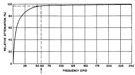
Fig. 8. Attenuation characteristic of an untuned law-pass filter.
Most power supply filters fall into the classification of untuned low-pass filters having a frequency attenuation characteristic similar to that given in Fig. 8.
This curve is drawn with frequency as its horizontal axis and relative attenuation as its vertical axis. In a typical power-supply filter, there is theoretically no attenuation of the pure d-c component (zero cycles per second.) This assumes that the inductances have zero resistance. Thus the curve must start at the origin of the axes.
The attenuation then rises rapidly and approaches 100% at some high frequency, the approach being asymptotic to the 100% ordinate. Assuming that the attenuation at 280 hz is complete, and accepting the fact that the attenuation at zero hz is zero, the vertical axis may now be divided into percentages to indicate the relative attenuation at various frequencies. Thus, the attenuation in the curve of Fig. 8 for the 60 hz component of normal line a-c is approximately 95 %. There is a continuously rising curve of impedance as the frequency increases. To realize acceptable filtering action the frequency at which attenuation begins (fa) must be as low as possible.
For 60 cycle power supplies, fa must certainly be no higher than 40 hz. The methods of incorporating fa in filter calculations will be discussed later.
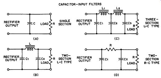
Fig. 9. Capacitor-input filters. (A) Single-section (B) Two-section L-C type
(C) Three-section L-C type (D) Two-section R-C type.
4. Ripple Voltage, Capacitor-Input Filter
Reduction of output ripple voltage or residual hum to the lowest figure commensurate with the permissible bulk and cost of the system is one of the prime purposes of the filter network. The factors contributing to the final value of the ripple voltage are the size of the filter components, the magnitude of the load current, the frequency of the pulsating supply (assumed as either 60 hz or 120 hz throughout this guide) , and the number of filter sections (Fig. 9) . Starting with the simplest type of filter (Fig. 9A) , a single-section capacitor arrangement, the ripple voltage can be determined from equation (2) . The equation has been simplified to yield a close approximation of the ripple voltage in terms of percent of its un filtered value. Specifically, percent ripple expresses the ratio of the rms value of the ripple to the d-c value. Thus, a power supply which provides 500 volts rms d-c with a ripple of 3% contains 15 rms volts of residual hum. Examples of maximum permissible ripple percentage for different applications are:
Transmitter, unmodulated . . . .. 5 % ;
Table-model radio . . . . . 1 % ;
Voice transmitters.
High-fidelity amplifiers
(2)
... where f. = pulsating supply frequency, hz.
Rr. = load resistance, ohms, C1 = capacitance, µ.f
Example: Find the percent ripple of a single-section filter of the capacitor-input type used after a full-wave rectifier if the load resistance is 10,000 ohms and the filter capacitor has a value of 20 µf. Assume a 60 hz line frequency.
Solution: Since the rectifier is full-wave, the ripple frequency is 120 hz. Substituting the values given in equation (2) :
As shown in equation (2) , when the supply frequency is fixed, the ripple percentage can be reduced by increasing the load resistance or the capacitance of the filter section, or both. Although it is possible to obtain low ripple by making the capacitance increasingly larger, it is not economical, as large capacitors are expensive. Further, if the load varies over an appreciable range, such a filter arrangement displays poor voltage regulation. The preferred alternative is adding one or more filter sections.
Equation (2) is equally valid for finding the ripple percentage output of the first filter section of a multi-section network. Assuming that an inductor and a second capacitor are added as in Fig. 9B, the ripple percentage may now he found from equation (3).
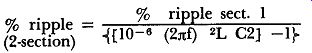
(3)
(2-section) , n: r where L is the inductance of the choke in henries and C2 is the capacitance of the second capacitor in µf.
Example: Assume that a 10-henry choke and a second 20-µf capacitor are added to the filter system of the previous example. Find the percent ripple output from this section.
Solution: The percent ripple as previously obtained was 0.94%, Thus:
= 0.0085%
The efficacy of the second filter section is thus easily established. A percent ripple figure of this low value is suitable for most applications, except possibly those involving extremely high-gain amplifiers.
In a manner analogous to the preceding the reduction in ripple percentage due to a third filter section may be computed using a slightly modified form of equation (3) . In this case, the percent ripple for section 2 would appear in the numerator, while the values of the second choke and third filter capacitor would be substituted for Land C in the denominator.
The approximate determination of the residual hum of a resistance capacitance filter (Fig. 9D) is handled in much the same way. Equation (ll) is employed to find the percent ripple from the filter capacitor C1; then, the output ripple is calculated from equation (4) .
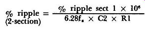
(4)
... where R1 = resistance of series filter resistor in ohms.
5. Output Voltage and Voltage Regulation, Capacitor Input
The d-c component of the pulsating voltage that appears at the output terminals of a full-wave rectifier may be shown to be related to the peak voltage across the same terminals by equation (5).
(See Fig. 10.)
2 d-c component = - X peak value = 0.638 E (5)
n: where E is the peak voltage.
If a capacitor is now connected in shunt with the output terminals, it charges up to nearly the peak voltage, E, if the load resistance is infinite (load current zero) and remains that way until current is drawn. As the load current increases, the average voltage across the capacitor diminishes because it is supplying load current throughout the nonconducting interval.
It is also clear that larger values of capacitance tend to maintain the d-c output voltage closer to the peak value because their potential does not drop as much for a given load during the nonconducting interval.
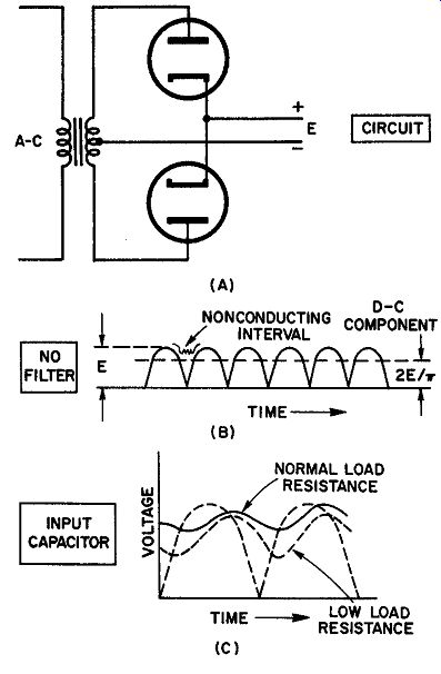
Fig. 10. (A) Full-wave circuit, no filter. (B) Output waveform of full-wave
rectifier. (C) Capacitor charge and discharge curves for large and small load
currents.
A capacitor-input filter is characterized: by a d-c output voltage usually substantially larger than the average value of the d-c input voltage to the filter; by a diminishing voltage as the load current increases; and by a smaller ripple component for large values of capacitance.
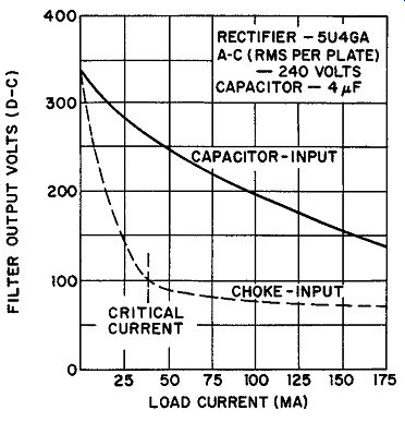
Fig. 11. Curve put voltage vs showing out load current.
The voltage regulation of a capacitor-input filter is poor because of the inability of the capacitor to maintain nearly peak voltage as the load current rises. In Fig. 10C the average output voltage with larger load currents is smaller than it is for small load currents. The output voltage vs load current curve of a typical capacitor-input filter power supply is illustrated in Fig 11. It is important to recognize that the ripple voltage must increase as the d-c output component decreases. Hence, capacitor-input filter systems are afflicted by increasing hum voltages with larger load currents.
Capacitor-input filter systems are used in small receivers, public address systems, and low-powered transmitter power supplies. When the amount of power required is large, choke-input filters are generally preferred. If regulation is important, as in power supplies that feed class-B amplifiers, capacitor-input is usually unsatisfactory.
6. Rectifier Considerations in Capacitor Input Filters
Filter systems introduce a peak current factor in the selection of a rectifier which does not enter into design considerations when filters are not used. Rectifier tubes are normally rated in terms of both d-c output current and peak current per plate. For example, the 5U4-GA has a d-c output current rating of 225 ma and a peak plate current rating per plate of 675 ma.
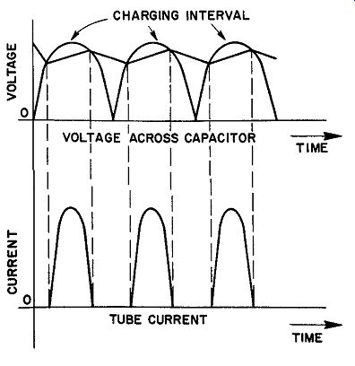
Fig. 12. The relationship between current through a rectifier tube and the
voltage across the input capacitor in a capacitor-input type of filter network.
During operation, the plate current in the rectifier flows in short pulses. The flow occurs only during the period when the input capacitor must be brought back to peak charge, after having discharged a portion of its energy into the load. The peak current that flows during this interval is a function of the load resistance particularly, and of the transformer secondary impedance to a somewhat lesser degree. A low value of load resistance discharges the input capacitor during the non-conducting portion of the cycle to a much greater extent than a high load resistance. Hence, the charging current flowing through the rectifier to restore the capacitor to its peak potential is also large. The only factor that limits the peak value of the charging current is the input impedance (transformer secondary impedance) to the rectifier.
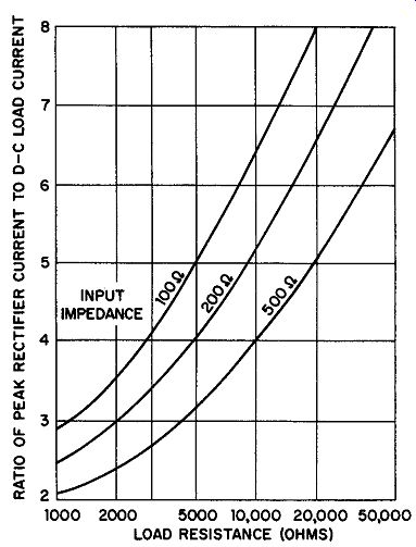
Fig. 13. Graph showing the relationship between the d-c load current and the
rectifier peak plate current with capacitor-input filter for various load and
input resistances. (ARRL Handbook).
The relationship between the current through the tube and the voltage across the input capacitor is shown in Fig. 12. Note that plate current flows only during the capacitor charging interval. The ratio of peak plate current to d-c output current is high. This means that the rectifier tube must be selected for high-peak current rating, even when the d-c output current does not appear to warrant it.
The ratio of peak to d-c output current may be found from a set of curves such as those given in Fig. 13. To use the curves, the load resistance of the power supply is first determined from the ratio of d-c output volts to d-c output amperes. The transformer impedance (input to rectifier) is then taken from the manufacturer's data, and the ratio of peak to d-c load current is found at the inter-section of the input impedance curve and the load resistance co ordinate. Three curves are given to permit interpolation for any value of input impedance between 100 and 500 ohms.
Example: A transformer having an input impedance of 100 ohms provides a d-c output from the rectifier filter system of 400 volts. If the total load current is 125 ma, find the peak rectifier plate current.
Solution: First determine the load resistance.
400 RL = .125
Rt = 3200 ohms
Referring to the curves in Fig. 13, we find that a load resistance inter sects the 100 ohm input impedance curve at a ratio of 4.25 to 1. Thus, for a load current of 125 ma, the peak rectifier current rating for this example must be at least 4.25 x 125 = 532 ma. A check through the tube manual tables discloses that the 5Y3-GT, for example, has a full-load d-c output current rating of 125 ma, but its peak plate current per plate rating is only 400 ma. A tube like the 5U4-GA with a peak current per plate rating of 675 ma would have to be used here.
7. Choke-Input Filter -- Critical and Optimum Inductance
A choke-input filter system utilizes an inductance between the cathode of the rectifier and the first filter capacitor. Such filter net works may be a single choke and one capacitor, or two chokes and two capacitors, as shown in Fig. 14. It is possible to select the input choke L of such value as to cause the current through it to be continuous when the rectifier is a full-wave type. That is, the current through the choke never drops to zero. It is sustained by the collapsing field of the inductor during the non-conduction portion of the a-c cycle. If the load resistance is so large that the load current cannot produce a sizable magnetic field in the choke, this condition cannot be realized. The filter system behaves, then, very much like a capacitor-input type. Only after the load current rises above a definite critical value with relation to the choke used, can the condition of continuous current be obtained.
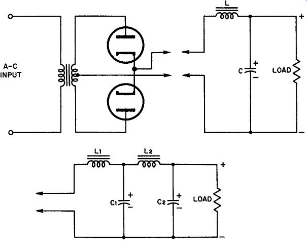
Fig. 14. Choke-input filter configurations normally encountered in power supplies.
For a given power supply, there exists a value of inductance which insures that the current into the filter does not go to zero during any portion of the cycle. Its value is a function of the load current (or load resistance) and is given by the approximate equation (6). This equation applies to the important 60 hz case in which a full wave rectifier is used.

(6)
where RL is the total load resistance consisting of the device being powered, the bleeder, the leakage of the filter capacitors and the resistance of the choke itself.
In practice, a minimum inductance safety factor of 100% is employed. That is, the optimum inductance for a filter choke is considered to be twice the critical inductance required.
Example: Find the optimum inductance for a single-phase, full-wave, choke input filter system in a power supply with these characteristics (60 hz supply):
D-c output voltage .. 300 volts; Minimum load current . 100 ma; Choke resistance .. 100 ohms; Bleeder resistance ..... 20,000 ohms.
Solution: First find the external load resistance by dividing the output voltage by the minimum load current: R = 300 volts = 3000 ohms
0.1 amp
The external load is in parallel with the bleeder resistance, hence, the equivalent load is:
3000 X 20,000
Load = 3000 + 20,000 = 2610 ohms
Since the choke is in series with the net load, the actual load resistance is the sum of the choke resistance and the equivalent load or:
Actual load = 100 + 2610 = 2710 ohms.
Equation (6) determines the critical inductance.
2710 . L. = 1130 and L0 = 2.4 henries
Finally, the optimum inductance is twice the critical inductance, so that: L0 = L0 X 2 = 2.4 X 2 = 4.8 henries
8. Ripple Voltage of Choke-Input Filter Systems
Two fundamental equations are generally used for determining the ripple voltage (in percent) that can be expected from choke input filters. These equations are approximate, but practical. The solutions obtained with them are adequate approximations for circuit design purposes.
For a single-section, choke-input filter consisting of one inductance L1 (henries) and one capacitance C1 (µf) used with a full-wave rectifier on a 60 hz line, the ripple percentage is given by:
... where L1 is in henries, and C1 in µf
(7)
Example: Determine the percent ripple expected from a single-section choke input filter that uses a 10-henry choke and an 8-µf capacitor.
Solution: Substitution in equation (7) yields:
= 1.25%
When the filter network contains two chokes and two capacitors and is used at 120 cycles, the equation for ripple percentage becomes: where L1 and L2 are expressed in henries, and C1 and C2 in µf

(8)
Example: In a full-wave power supply used on 60 hz, the filter consists of an input choke of 5 henries, a first filter capacitor of 8 µf, a second filter choke of 30 henries, and a second filter capacitor of 8 µf. Find the o/o ripple.
Solution: Substituting in equation (8) .
9. Voltage Regulation of Choke-Input Filters
The regulation of a choke-input filter is superior to that of a capacitor-input filter. Calculations for voltage regulation percent- age are handled by the same equation that was employed for capacitor-input filters (equation 1). Referring to Figure 11, it is seen that the output voltage drops sharply for small load currents until the critical current is reached. For this value, the inductance of the choke becomes critical and the regulation immediately improves.
Note that although the output voltage for output current between about 50 ma and 175 ma is lower than for the equivalent capacitor input filter, it is maintained at a fairly constant value. Choke-input filters are used in applications where voltage regulation of this order is required.
Choke-input filters possess another positive advantage in that their peak-to-average plate current ratio is appreciably small. If the load resistance and input choke inductance are related approximately as given in equation (9) , the rectifier peak plate current does not exceed the d-c load current by more than 10%. This is much smaller than the margin allowed in any modern rectifier, hence it is quite safe. Note that this value of choke inductance is approximately the same as the optimum inductance as previously defined.
Total load resistance minimum value o = 500 (9)
Example: The total load resistance on a power supply, taking all components into account, is 10,000 ohms. What is the minimum acceptable value for the input choke in the filter?
Solution: Using equation (9)
= 20 henries
Example: A 5Y3-GT rectifier has a d-c current rating of 125 ma and a peak plate current rating per plate of 400 ma maximum. If the tube is used before a choke-input filter in which L1 exceeds the optimum inductance at 125 ma, what is the maximum peak current to be expected on full load? Solution: The peak current will then be 125 ma + 10% of 125 ma = 1!17.5 ma which is well below the peak current rating of the tube.
10. The Output Capacitor
The output capacitor of any type of power supply, as viewed by the load, is in parallel with the filter choke and rectifier components.
At audio frequencies, or at other high frequencies, the output impedance of the power supply is essentially the same as the reactance of the last capacitor. To prevent instability and positive feedback problems in audio systems, the maximum output impedance of the power supply must be very low. Usually, this maximum impedance is specified for the lowest frequency to be reproduced in the audio amplifier. In this case, the minimum permissible value for the output capacitor in µf is obtained from equation (10).

(10)
… where Z (ohms) is the specified output impedance maximum and f (hz) is the lowest frequency to be reproduced in the amplifier.
Example: The lowest frequency to be handled by a high-fidelity amplifier is 20 hz. The specified maximum output impedance is 500 ohms at this frequency. Find the minimum output capacitance.
Solution: Use equation (10) .
159,000 C0 min = 500 X 20
= 15.9 µf 11.
Swinging Choke
Equation (6) points out that the value required for the critical inductance in a choke-input power supply depends upon the load resistance value, hence, upon the load current. Since the relation between the required choke inductance and the current is an in verse proportion, an appreciable improvement may be made in voltage regulation characteristics by utilizing this fact in power supplies that handle class-B amplifiers, or similar systems in which large variations of load current are anticipated.
[1. Schure, A., Resonant Circuits. New York, John F. Rider Publisher, Inc., 1957]
Swinging chokes are usually rated in terms of the maximum d-c current they carry, and the range of inductances over which they swing for various load currents. Thus, a typical swinging choke might be rated as 5 to 30 henries, 200 ma. This means that the inductance of the choke is 30 henries at zero load current and 5 henries at a current of 200 ma. At small values of load current, the inductance of the choke is therefore between 30 henries and 5 henries, but closer to the larger figure. In designing swinging chokes, manufacturers calculate their construction specifications on this basis: the choke must have optimum inductance at small values of load current and critical inductance at the larger values of load current.
12. Tuned Low-Pass Filters
Figure 8 shows the superior attenuation characteristics of a tuned low-pass filter1 in contrast with an untuned type at the frequency of resonance. Since the alternating supply frequency in virtually all places where a-c is used is now maintained sufficiently constant for synchronous clock motors, it is possible to design a tuned filter system economically. However, close design limits are imposed by the nature of the system, and so tuned filters are not as popular as their advantages appear to warrant.
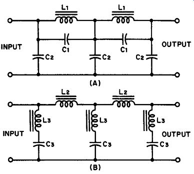
Fig. 15. (A) Parallel-tuned filter having attenuation characteristics given
In Fig. 8. (B) Series-tuned filter with similar characteristics. In both cases,
inductor and capacitor calculations must be carefully performed to obtain sharp
characteristics.
Figure 15 illustrates two types of tuned filters whose attenuation characteristics are similar. Design equations are provided for those who wish to build them.
For the filter system of Figure 15A, the following equations may be used:
The following equations apply to the filter system of Fig. 15B

(18)
where k = fr/fa in which fr = resonant or line frequency, and fa is the frequency at which attenuation begins (Fig. 8.)
13. R-C Filters for Power Supplies
Resistance-capacitance R-C filters have become extremely popular in recent years because they provide adequate filtering when correctly designed, and represent a compromise between cost and bulk on the one hand, and performance on the other. Low-gain audio amplifiers, public-address systems, high-voltage power supplies for television receivers, and table-top radio receivers are a few examples of their wide application.
A typical R-C filter appears in Fig. 16. Its operation is approximately as follows: C1 charges nearly to the peak voltage of the power supply on the conduction portion of the cycle. It is discharged through R1 and R2, the latter being the bleeder resistance in parallel with the load. Since R2 is much larger than R1, most of the output voltage develops across it and is applied to C2. Although this ...
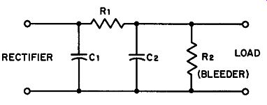
Fig. 16. A representative R-C filter system used in the high voltage power
supply of a television receiver.
.... capacitor can discharge through either R1 or R2, the polarity of the voltage across R1 discourages the discharge through this resistor. Hence, most of the discharge occurs through R2. Typical values for television high-voltage supplies are 0.05 µf for C1 and C2, 500,000 ohms for R1, and 5 megohms for R2.
In radio receivers the bleeder is usually omitted, the plate and screen current drain of the power amplifier serving as the principal load. In such power supplies, the capacitors are of the order of 40 to 60 µf, while R1 is made approximately 1000 ohms.
R-C filters have very poor regulation, due to the substitution of a resistor for a choke. For this reason, R-C filters are never used where the power requirements are high, because the power loss in the filter resistor may become prohibitive under these conditions, and the regulation is bad.
14. Graded Filters
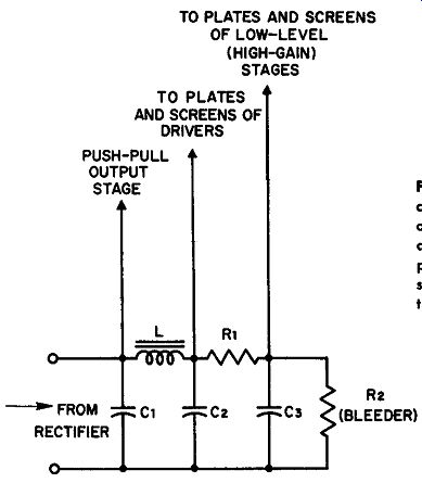
Fig. 17. A graded filter consisting of one L-C and one R-C section. Such filters
are economical and tend to produce decoupling which stabilizes the performance
of the equipment.
Various stages in multisection electronic equipment often require different filtering. For example, the high-gain stages following a microphone or playback in a high-fidelity amplifier system demand extremely low ripple if intolerable hum is to be avoided; in the same system, however, the power output stage -- usually push-pull--- may be supplied with plate and screen power having consider ably more hum-voltage contact. It would be unwise and uneconomical to supply all the stages with the same, well-filtered d-c because this procedure increases bulk and cost, and because advantage is not taken of the isolation characteristics inherent in a graded filter (Fig. 17) to suppress regeneration.
In the example of Fig. 17, the power supply provides voltages for the plates and screens of two high-gain voltage amplifiers, a class-A driver stage, and a push-pull class-AB! power output section. The last obtains its d-c power directly from the filter capacitor, since no more filtering than this is needed for a stage operating at this high level. The driver stage obtains power at a point where a substantial amount of filtering has been accomplished (after the filter choke), thus making use of C1, L, and C2 as filter components. The low level, high-gain voltage amplifiers, are supplied d-c from a point that receives maximum filtration and where the ripple voltage is down to an acceptably reduced figure.
The graded filter used in the example makes it possible to select a choke of much smaller current rating, since the largest part of the circuit current flows in the push-pull output stage which is not fed through the choke. Similarly, the filter resistor may be made very low in wattage rating since the high-gain stages demand very little current. Note, that the resistor R1 decouples the high-gain stages from the driver and that choke L does the same thing for the driver and output stage.
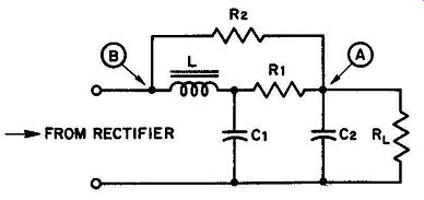
Fig. 18. A cancellation filter for reduction of ripple voltage at a specific
supply frequency.
15. Cancellation Filters
Figure 18 illustrates a cancellation-type of filter network using a choke and two resistors.
Its principle of operation is as follows: the ripple-frequency current passing through L and R1 to the load is shifted in phase nearly 180° at point A with reference to the input phase at point B. The same frequency current passing through R2, however, has the same phase as the input current. Hence, at point A there are two out-of-phase ripple currents that can cancel each other, theoretically. To realize a phase shift as large as 180°, the Q of the filter choke would have to be very high. Since most chokes used for filter components have Q's of the order of 9 or 10, at the most, the cancellation is not perfect but sufficient enough to improve filter action to a profitable extent. The addition of one more filter section (R-C) can result in perfect cancellation, but the critical nature of the design required makes this a rather unpopular alternative to straightforward brute force filters.
16. QUIZ
1. Explain why smaller filter components are needed for full-wave power sup plies than for half-wave supplies at the same line frequency.
2. Define voltage regulation. Describe the steps in filter design that are taken to obtain the best possible voltage regulation.
!I. Discuss and compare capacitor- and choke-input filter systems from the point of view of output voltage and voltage regulation.
4. Find the percent ripple in a full-wave power supply of the capacitor-input type in which the load resistance is 20,000 ohms and the filter components have the values given below. The line frequency is 60 hz.
C1 = 60 µf
C2=20µf
L = 9 henries
5. Explain why a smaller rectifier tube may be used with a choke-input filter having the same input and impedance characteristics as an equivalent capacitor-input filter.
6. A transformer having an input impedance of 50 ohms is used to supply 300 volts d-c to its load at 200 ma. Find the peak rectifier plate current.
7. Define critical inductance, optimum inductance.
8. Determine the percentage ripple from a filter system in which the following apply:
Type: choke-input
Rectification: half-wave
Line frequency:
60 hz L1, L2: 15 henries each C1: 10 µf C2: 4 µf
9. Describe the nature and operation of a swinging choke.
10. With the aid of a diagram, explain the operation of a cancellation filter.