AMAZON multi-meters discounts AMAZON oscilloscope discounts
RESISTANCE
All substances are made up of combinations of various atoms.
This is theory; but this assumption, and others associated with it, have been essential to the progress made in electricity and electronics. Details of this theory may be found in many textbooks dealing with electricity and electronics. Only the highlights relating specifically to the concept of resistance will be considered here.
All atoms consist of a core or nucleus around which rotate one or more electrons. Each electron contains (or consists of) one unit of negative charge. The nucleus contains electrically neutral particles, together with others (protons), each of which contains a unit of positive charge. If the atom is not subjected to any electrical or chemical action, the number of electrons rotating about the nucleus is exactly equal to the number of unit positive charges in the nucleus. The arrangement of orbits in which the electrons rotate around the nucleus in various layers or "shells" is characteristic of the element-copper, silver, gold, uranium, etc.
There are approximately 100 basically different types of arrangements known at present, and these correspond to the different elements. All electrical and chemical actions affect only the outer electrons of the atom.
Insulation and conduction. If a source of voltage is connected across an object so that one end is positive while the other is negative, some outer electrons of the atoms in the object will be repelled away from the negative end and attracted toward the positive end. The number of outer electrons which are affected in this manner is determined by how strongly the outer electrons are attracted to the nucleus. The weaker this bond, the greater will be the number of outer electrons that join the flow to the positive terminal. Materials such as glass, plastics, rubber, and baked clays exhibit strong bonds between the nuclei and outer electrons and are known as insulators. These permit only a very small number of electrons to break away from their atoms to enter the current flow. If the outer electron bond is weak, as in copper, silver, aluminum, and other metals, a large number of electrons join the flow to the positive terminal. Such materials are known as conductors.
Resistivity. The opposition which any specific substance offers to the free flow of electrons is known as its resistivity and is measured in ohms, as defined by the familiar Ohm's law. Resistivity may be expressed as the number of ohms of opposition offered by a cube of material which measures one centimeter on all sides.
This unit is known as the ohm-centimeter. In the English system of measurement the ohm-inch is used. When the material is in the form of wire, resistivity is expressed as the number of ohms of opposition offered by a wire I foot long and 1 mil (0.001 inch) in diameter. This unit is known as the ohm per mil foot. The resistivity of various materials is listed in engineering handbooks and tables of physical constants. Values for a few common examples are listed here:
TABLE 1-1
Material Resistivity
Aluminum Carbon (graphite)
Chromium Copper German silver Gold Iron (pure)
Iron (tempered steel)
Lead Platinum Silver
In most branches of engineering, as well as in the theoretical sciences, tempera ture is expressed in degrees Centigrade (°C). The freezing point of water is ,2° Fahrenheit (0 F) or 0-c. The boiling point of water is 212°F or 100°c.
The following relationship can be used to convert temperature from one scale to the other: degrees 1'' = 9/5 degrees C + ,2.
Note: 1 micro-ohm 0.000001 ohm.
The reciprocal of resistivity (1 divided by the resistivity) is known as conductivity. The unit of measurement of this characteristic is the mho, a reverse spelling of the term ohm.
Total resistance. When a substance is formed into a rod or wire, the major interest is not in its resistivity but in the total resistance. This quantity is the total number of ohms of opposition offered to current flow between its ends. Total resistance may be calculated from the relationship: resistivity X length Total resistance (ohms)=-------- area of cross section A rod or length of wire has a total resistance of l ohm if I ampere of current flows through it when 1 volt of electromotive force is applied to its ends.
CUTAWAY VIEW (A) COMPOSITION RESISTOR CUTAWAY VIEW (B) WIREWOUND RESISTOR INNER INSULATING TUBE (C) FIXED TAPPED WI REWOUND RESISTOR
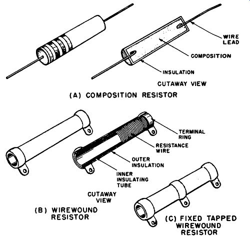
Fig. 1-1. Fixed resistors, appearance and construction. (A) Composition resistor.
(B) Wirewound resistor. (C) Tapped wirewound resistor.
RESISTORS
In electrical and electronic equipment it is often required to use electrical resistance to limit current flow in various circuits, to form voltage dividers, to establish required voltages at the different elements of a vacuum tube, and to form the great variety of special arrangements considered in textbooks concerning electricity and electronics. In all of these applications the designer requires specific quantities of total resistance for insertion into the various circuits. The components which contain these known values of total resistance are known as resistors. There is a wide variety of resistors available, but they may be divided into the broad groups of fixed, adjustable, and variable resistors. These groups will be introduced here, and details concerning the many commercial types will be given in Section 2.
Fixed resistors. A fixed resistor has its total resistance deter mined during the manufacturing process, and there are no pro visions for changing this value. The user orders the total resistance required from a broad selection of standardized values, and other values are available on special order. Of a variety of fixed resistor types available, the composition and wirewound resistors shown in Fig. 1-1 (A) and (B) respectively are two types commonly found in present-day equipment. The construction details shown in Fig. 1-1 will be described in Section 2. Wirewound resistors are also available with connections, called taps, made to any desired part of the resistance element, as shown in Fig. 1-1 (C).
Adjustable resistor. Adjustable resistors, as shown in Fig. 1-2, are generally merely specialized forms of wirewound fixed resistors.
The difference is that the wire of the resistance element is at least partly exposed, and a movable clamp-type terminal is supplied to make contact with the element at any desired point along its exposed sections. Moving the terminal changes the resistance between either of the end terminals and the clamp terminal. This adjustment is not intended for continuous use, since it is mechanically inconvenient and time consuming. Adjustable resistors are intended for use in applications where they are set to the required value by the equipment manufacturer, and further adjustment by the user is generally unnecessary.
Variable resistor. An example of a variable resistor is shown in Fig. 1-3 (A), and the simplified internal construction appears in Fig. 1-5 (B) and (C). This type has its resistance element inside the circular container, and a movable terminal is also contained within. The movable terminal is easily shifted to any desired part of the resistance element simply by turning the shaft coming out of the container. Variable resistors are intended for use in applications where the equipment user has frequent requirement for adjusting the resistance, as in tone, volume, focus, and brightness controls. Variable resistors are made with either composition or wirewound resistance elements, and all considerations to be mentioned in connection with fixed resistors having those types of elements also apply to variable resistors.
CONSIDERATIONS AFFECTING RESISTOR SELECTION
An equipment designer cannot order resistors simply on the basis of the total resistance values he obtains from his calculations.
It is in the nature of resistors that they cannot be manufactured on a production-line basis at the exact total resistance values desired. They can, however, be made within certain specified limits of a desired value. Thus a resistor is usually marked with its total nominal or "rated" resistance value, together with a symbol indicating the manufacturing tolerance. The tolerance is usually indicated in terms of the percentage by which the resistor may be higher or lower in value than that indicated by its nominal resistance markings. In addition, the values supplied by the manufacturer are not completely stable, since the to~ resistance changes with age, temperature, humidity, amplitude of applied voltage, and various other conditions.
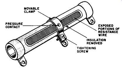
Fig. 1-2. Adjustable resistor.
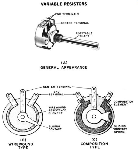
Fig. 1-3. Variable resistors. (A) General appearance. (b) … wirewound type.
(C) Simplified construction, composition type. (B) WIRE-WOUND TYPE VARIABLE
RESISTORS (A) GENERAL APPEARANCE CENTER TERMINAL END TERMINAL WIREWOUND RESISTANCE
ELEMENT SLIDING CONTACT (C) COMPOSITION TYPE COMPOSITION ELEMENT
While certain resistor designs eliminate most of these undesirable effects, their cost is considerably higher than those designs where little or no attempt is made to prevent variations of the total resistance value. The equipment designer must evaluate the special features and cost of each type and manufacture against the particular requirements of each specific application. In some types of circuits the least expensive resistors perform in a most satisfactory manner, but in other applications even the most highly corrected and expensive types fail to meet some requirements.
Thus the equipment designer, builder, or experimenter must be well acquainted with the considerations involved and with the special features of each resistor type to meet the requirements of each application in the most economical manner. The following paragraphs review the major considerations affecting resistor selection.
POWER DISSIPATION
When a voltage is connected across a resistor, electrons flow from the negative to the positive terminal. Since the resistance opposes the flow of electrons, the electromotive force is expended against opposition. Work is done and electric power is expended within the body of the resistor. The result is the generation of heat.
The only way for the heat to be dissipated from the body of the resistor is by conduction through the leads, by convection to the air, and by radiation to the surroundings. Because of the small diameter of the lead wires, little heat can be dissipated in this manner. The heat which can be dissipated by convection and radiation is related to both the temperature and surface area of the object. For equal heat loss the total surface area may be decreased as the temperature increases. Also, if the surface area is insufficient to dissipate the heat generated within, the temperature will rise to the level required to lose that heat, and the resistance element may be burned out in the process.
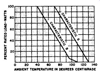
Fig. 1-4
Either the construction of the resistor must be designed to withstand extremely high temperatures, or the resistor surface area must be made large enough to dissipate sufficient heat to keep the temperature down to safe limits. A combination of both of these methods is used by resistor manufacturers.
For any given total resistance value, the amount of current flow, and consequently the heat generated, is dependent upon the voltage applied across the resistor. This voltage, of course, will depend upon the circuit in which the resistor is to be used.
Consequently, manufacturers generally make each standard total resistance value available in resistors of a number of different power ratings. In any particular application the power to be expended in a resistor may be calculated from the voltage applied across it and/or from the current flowing through it, according to any of the following relationships:
Power (watts) = volts X amperes
Power (watts) = (amperes) 2 X resistance (ohms)
(volts)2
Power (watts)=-------
resistance (ohms)
The result of this power calculation is not necessarily equal to the actual resistor power rating. First, there are only a limited number of standard power ratings available for any particular total resistance and type of construction. Second, the manufacturer's power rating is usually based on a condition in which the resistor is mounted in free air at a temperature of 40-c (104-F). When the resistor is to be mounted in an enclosed space in which air circulation is restricted or in which the operating temperature will be above 40°C, a resistor with a power rating higher than the value indicated by the preceding formulas must be chosen. To choose the proper substitute, it is necessary to derate a standard power rating. This means assigning a lower power rating to the substitute resistor.
The method of assigning a lower power rating is by a derating curve (Fig. 1-4). Such curves are sometimes supplied by the resistor manufacturer and are almost always supplied by military standards agencies as a specification for the use of resistors in military equipment. According to the curves shown, which are for composition resistors, a resistor with the characteristic code B (designed for operation below 40°C), and nominally rated at 1 watt, may be operated at 1 watt if the temperature of its immediate surroundings remains below 40°C. If the temperature of these surroundings is at 65°C, the resistor must not be used to dissipate more than 0.5 watt, and at 100°C the maximum power rating that can be used is 0.05 watt. Thus, if a designer requires a composition resistor that will dissipate 1 watt at 65°C, he must order a 2-watt resistor.
The 20-watt size required to dissipate 1 watt at 100°C is not available in composition resistors, so a wirewound type with its own derating curves will have to be investigated. A derating curve for resistors with the characteristic code G (designed for operation below 75°C) is also shown in Fig. 1-4.
TEMPERATURE EFFECTS
Closely associated with power-dissipation considerations are the effects of temperature upon total resistance. Power-dissipation considerations are concerned mainly with preventing the tempera ture rise from destroying the resistor. But also to be considered is the fact that temperature increase causes greater agitation of the individual atoms or united groups of atoms (molecules) in a material, thereby restricting the path through which the electron current can pass. In most cases this causes an increase in resistance, although in some unique cases there is a decrease in resistance.
This is important because the total resistance value required for proper circuit operation may be allowed to differ by particular amounts which are determined by the specific application. In some cases the total resistance may be 20% high or low without any undesired effect on circuit operation. in other applications, a change of more than 1% cannot be tolerated. Temperature effect must be considered.
Resistors intended for precision applications often have a temperature coefficient value supplied by the manufacturer. This value defines the expected percentage of resistance change per degree of temperature difference from a specified temperature:
Resistance at test temperature - resistance at 25°C
------------------- x 100
Resistance at 25°C X temperature change
= temperature coefficient.
The magnitude of this resistance change can be seen from Table 1-2. The table shows for two types of insulated composition resistors the maximum permitted percentage resistance change for temperature variations above and below a reference temperature of 25-C (77°F).
=============
TABLE 1-2
Maximum percentage resistance change
Resistance at 21-C
1000 ohms and below
Above 1000 ohms to 10,000 ohms
above 10,000 ohms to 0.1 megohm
above 0.1 megohm to 1 megohm
Above 1 megohm to 10 megohms
Above 10 megohms to 100 megohms
At -55°C At +105°C
Type E Type F Type E Type F
===================
When composition resistors are soldered into the equipment, the heat transmitted through the attaching leads may cause a resistance change of as much as 3% for the ¼-watt size and 1% for the 1-watt size. Approximately half the resistance change disappears after cooling, but the remainder is generally permanent.
Thus, ordinary composition resistors may be selected for a total resistance accuracy of about ±1%, but this accuracy may well be lost in the soldering process unless special techniques or special tools are used to prevent the resistor body from being heated. If a pair of heavy pliers is used to grasp the lead between the body and the end being soldered, most of the heat will flow into the pliers rather than into the resistor body. If accuracies of ±1% or better must be maintained, the most certain method is to use the temperature-stabilized types which will be considered in Section 2.
With these types the effect of soldering are reduced to 1/10 or less than the change found in ordinary composition resistors.
VOLTAGE EFFECTS
Due for consideration under voltage effects are voltage co efficient and voltage ratings such as insulation strength, short-term overload, and maximum overload voltage.
Voltage coefficient. In the case of low resistances, large currents flow for relatively low applied voltages, and the maximum voltage that can be applied is determined by the resistor power rating.
However, in the case of composition resistors with high resistance values, a separate voltage effect takes place: resistance decreases with increasing applied voltage. For composition resistors of 1000 ohms or more the percentage decrease of resistance per applied volt can be determined from the relationship: Voltage coefficient= 100 x ---- E,-E, where E, equals the rated continuous voltage, E, equals 0.1 times the rated continuous working voltage, R, equals the resistance at rated continuous working voltage, and R, equals resistance at 0.1 times the rated continuous working voltage.
For ¼- and ½-watt composition resistors the voltage coefficient should not be above 0.035% per volt; for those with power ratings above ½ watt, the coefficient should not be more than 0.02% per. volt.
Resistance tends to decrease with increasing applied voltage because conduction takes place only through two or more carbon particles in contact with each other. Since the contact resistance of each such point is an inverse function of the voltage, the total resistance decreases with voltage. Conduction in a metal wire takes place because of a flow of free electrons between an extremely large number of atoms. Consequently, wirewound resistors have negligible voltage coefficients.
Voltage ratings. Besides considerations of voltage coefficient and maximum current, the maximum voltage that can be applied across a resistor is limited by the danger of voltage breakdown (arcing) along the length of the resistor body or through the insulation to a conductor (usually ground) in contact with the resistor body. Resistor manufacturers and government agencies often assign voltage ratings to resistors. Resistor users should be familiar with these ratings and with the general factors governing their use.
The resistance rating and power rating of a resistor are factors used to determine the maximum dc or rms, ac continuous working voltage that may be connected across a resistor. The relationship used to determine this rating for composition resistors is:
E_w =__/ PR ,
where E_w equals the continuous working voltage, P equals the power rating, and R equals the resistance rating.
Regardless of the results of this calculation, there is a maximum continuous working voltage which may be applied to these resistors.
The maximum short-term overload that may be applied across a composition resistor for periods of less than 5 seconds is generally 2.5 times the maximum continuous working voltage but in no case should exceed the value shown in Table 1-3. The insulation strength of resistors is that voltage which may be applied across a resistor and a conductor (usually ground) in close contact with its surface. Such voltage should never exceed twice the maximum continuous working voltage, unless the resistor is specifically dc signed for higher insulation strength.
Resistor power rating (watts)
TABLE 1-3
Maximum continuous working voltage (volts dc or rms ac)
HUMIDITY AND AGING EFFECTS
Maximum short-term overload (volts dc or rms ac)
Humidity. When standard resistors are exposed to constant conditions of high humidity such as tropical climates, there may be a resistance increase of as much as 7 to 10%. In temperate climates this effect may be only as great as from 2 to 4%. Prevention of moisture effects is accomplished by impregnating the structure with moisture-proof waxes, varnishes, plastics, or ceramics, or by sealing them in casings made of these materials. In such cases the maximum resistance change due to humidity may be kept to below 1%.
Aging. Even under stable temperature and humidity conditions, a resistor is subject to aging effects. When manufactured, it is subjected to mechanical and temperature effects which cause internal stresses in the body of the resistor. As time passes, these stresses are relieved by expansions, contractions, and warping.
Minute changes in the internal structure result, and small changes in resistance take place. After several months, resistance changes of 2 to 3% may occur. Special constructions are available which reduce aging effects to 0.5% or less.
One test for aging effects is the load-life test. In this test, a resistor is placed in a space maintained at 40°C, and sufficient direct current is passed through it to maintain a specified percentage of the resistor's rated power load. After 1000 hours in these conditions, the resistance change is measured. The results of such tests differ widely among the various resistor constructions, and only a manufacturer's specification of percentage change provides any useful information.
FREQUENCY EFFECTS
All resistors exhibit an effect in which the resistance for dc (R,) differs from the resistance for high-frequency current (R,). All resistors contain small amounts of capacitance and inductance in addition to resistance. At frequencies below 1 mhz, the capacitance behaves essentially as though a small capacitor were connected between the two resistor ends. At higher frequencies it exhibits more the effect of being distributed along the length of the resistor.
The inductance always has the effect of being connected in series with the resistor.
As will be indicated in Sections 4 to 6 of this guide, inductance and capacitance have different and complex effects when combined in series- and parallel-circuit arrangements. Depending upon the type of circuit arrangement and upon the specific quantities of inductance and capacitance contained therein, the effects sometimes add and sometimes cancel, to aid or retard the flow of electric current at different frequencies.
As a net result of these C and L factors, wirewound resistors show an increase in resistance as frequency increases. Roughly speaking, the high-frequency resistance rises to 1.1 times the dc resistance at frequencies of about 2 mhz and shows an increasingly rapid rate of increase at higher frequencies. When special non inductive windings are used, the resistance rise can be kept below 10% for frequencies up to 20 mhz or a little higher. In fact, the winding can even be designed so as to cause a resistance decrease with frequency rise.
In the case of composition resistors, the effective resistance decreases as the frequency rises. The higher the total resistance value, the lower is the frequency at which a noticeable change takes place. As an approximate example, a ½-watt, 1-megohm composition resistor has an effective resistance of about 750,000 ohms at 0.25 mhz and an effective resistance of about 500,000 ohms at 1 mhz. There is a relationship which can be used to predict the frequency characteristics of a composition resistor very roughly.
According to this relationship for a given type of construction, the ratio R1/R0 is a constant in all cases in which the products of R0 and fare equal. For example, in comparison with the previous example, a 100,000-ohm resistor has an effective resistance of 75,000 ohms at 2.5 mhz and an effective resistance of 50,000 ohms at 10 mhz. This relationship becomes increasingly incorrect at frequencies above 100 mhz.
The following calculations demonstrate this relationship: 1-megohm resistor at 250,000 hz:
Ro X f = 250,000,000,000
R 1/R0 = 0.75 100,000-ohm-resistor at 2.5 mhz: Ro X f = 250,000,000,000 R 1/R0 = 0.75 1-megohm resistor at 1 mhz: Ro X f = 1,000,000,000,000 R 1/R0 = 0.5 100,000-ohm resistor at 10 me: Ro X f = 1,000,000,000,000 R 1/R0 = 0.5