AMAZON multi-meters discounts AMAZON oscilloscope discounts
FIXED COMPOSITION RESISTORS
Construction. In this type of resistor the resistance element consists of a very finely powdered conducting material, such as graphite or carbon, mixed with a powdered insulating material, such as silicon or talc stone, together with a plastic binding material. These materials are pressed into the form of a rod with a wire lead imbedded part way into each end. This conducting core is covered with a layer of Bakelite with good insulating and moisture-resisting properties. The final construction, identified by the general appearance as previously shown in Fig. 1-1 (A), is known as an insulated composition resistor with axial leads.
Another type of construction, which is rarely found in present day equipment is the uninsulated composition resistor, sometimes known as the carbon resistor. The conducting element is made in the same manner, but the connecting leads are wound around the ends and are known as radial leads. No insulating material except paint is used on the body, and insulation is obtained by mounting the resistor so that it cannot come into contact with any other uninsulated components.
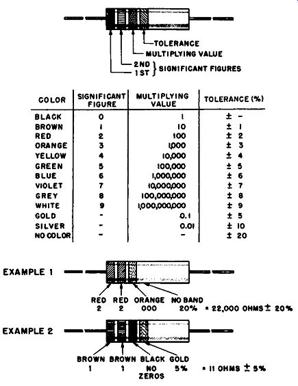
Fig. 2-1. Axial-lead Composition resistor color code and examples.
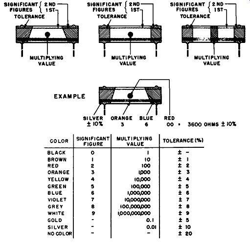
Fig. 2-2. Radial-lead composition resistor color code and example.
For any given power rating, all resistors have the same body size, regardless of the total resistance value. The total resistance is not adjusted by changing the length or diameter of the con ducting rod, but rather by changing the resistivity by the adjustment of the proportions of the conducting and insulating materials.
Advantages and disadvantages. Advantages of composition resistors are small size, low cost, good frequency-response characteristics, and available resistance values ranging from 10 ohms to 22 megohms. They are available with resistance tolerances of 20, 10, and 5% and with wattage ratings of ¼, ½, 1, and 2 watts. Disadvantages are that composition resistors are subject to aging effects and have high voltage and temperature coefficients. In addition, tolerances of less than 5% are not available except at substantially increased cost, and such lower tolerances are difficult 1<> maintain during the normal use of the resistor.
Color codes. A single standard color code has been adopted by the United States Armed Forces and the Electronic Industries Association (EIA), formerly the Radio, Electronics, and Television Manufacturers' Association (RETMA), for the purpose of identifying the resistance characteristics of fixed composition resistors of the axial-lead type. The details of this color code are shown in Fig. 2-1, together with examples of its use. The color code for the radial-lead types of construction, and an example of its use, is shown in Fig. 2-2.
------- R-L-C COMPONENTS HANDBOOK

TABLE 2-1 EIA Standards for Fixed Composition Resistor.
Preferred Values of Resistance (ohms).
Standard values. If resistors were made available in all possible resistance values, it would be impractical to maintain a stock of spares for repair purposes. To limit the total number of resistance values required to maintain a complete supply of spares, the Armed Forces and EIA have adopted a standard list of preferred resistance values. These values are shown in tabular form in Table 2-1.
Tolerances of ±20, ± 10, and ±5% are available in a full range from 10 ohms to 22 megohms. The values available at each tolerance rating are sufficient for all applications in which such a tolerance is suitable. Although special values are available on special order (and at increased cost), such special values would usually have closer tolerance requirements, so that precision resistors, to be considered shortly, would be used instead.
Standard body sizes. Just as the use of standard resistance values simplifies the maintenance of spare parts, the acceptance of standard body sizes assures that new resistors will take up the same physical space in the equipment as the parts they replace.
Standard body sizes have been adopted for use in American military equipment, and similar sizes are also used in commercial equipment. Typical sizes are listed in Table 2-2. Note that this does not mean that all fixed composition resistors of the same wattage rating have the same size. Some manufacturers make the standard wattage ratings with a significantly smaller body size. These small sizes generally perform as well as the larger ones and are very useful in miniaturized equipment.
TABLE 2-2
Standard Body Sizes for Insulated Composition Resistors
WIREWOUND RESISTORS, POWER TYPE
Construction. The general construction of wirewound resistors consists of a metal alloy wire wound around a solid or hollow core made of insulating material. See Fig. 1-1 (B). In power resistors the design emphasis is placed upon maximum power dissipation rather than resistance accuracy. This end is achieved by means of constructions which will withstand high operating temperatures and thus dissipate maximum heat without damage.
The usual construction method employed is to wind a single layer of resistance wire on a rod or tube of ceramic material. Metal rings with provisions for attaching terminals are crimped around the ends of the ceramic core, and the ends of the windings are connected to these rings. The windings and end rings are next coated with a ceramic paste which is then baked. Coatings which harden without baking are also used. The coating provides electrical insulation, holds the windings in place, and prevents mechanical and moisture damage. In addition, the ceramic coating is a good heat conductor, transmitting heat readily from the resistance wire to the surrounding air. The resistance value and wattage rating, plus any other identification, is printed directly on the coating. Color coding is not used.
Types of windings. In most power resistors the resistance wire is wound in a single layer. When it is required to obtain higher values of resistance without increase in size, the wire may be wound in several layers to obtain a greater length in approximately the same volume. When this is done, special precautions must be taken to obtain high-temperature-proof insulation between the layers.
Because wirewound resistors are constructed in the form of a coil of wire, they have inductance and distributed capacitance which may cause undesirable frequency response characteristics in the region of 1 to 5 mhz. Over a half-dozen special types of windings have been designed to reduce these effects. Most of these special windings are designed upon the principle of winding the wire so that current flow in adjacent turns is in opposite directions.
Some of these windings reduce inductive and capacitive effects sufficiently to make them negligible at frequencies of 20 mhz or higher.
The type of winding used by the resistor manufacturer is usually of little interest to the equipment designer. It is the manufacturer's data concerning the frequency-response characteristics of the resistor that is important. Power-resistor windings are generally classified as being either of the inductive or noninductive type. The large majority of power resistors available are of the inductive type-in which no attempt is made to correct the frequency-response characteristics.
Tolerances. Power resistors are generally supplied in tolerances of 10%. For resistances of more than 50 ohms it is not unusual to be able to obtain tolerances of 5% at little or no extra cost.
A number of types are available with tolerances as close at 1%, and some very special types are available with even smaller tolerances. Obtaining tolerances of less than 1% presents special problems, because high temperatures cause resistance changes which cannot be predicted with great accuracy. In addition, wire, such as nichrome, which will withstand high temperatures, has a large temperature coefficient which precludes close tolerances. Alloys, such as constantan, which have a low temperature coefficient must be operated at lower temperatures and cannot dissipate the same power in the same physical space. Precision constructions will be considered after a review of the characteristics of the major types of power resistors.
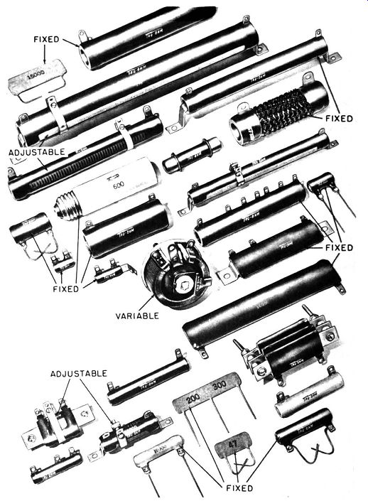
Fig. 2-3. Popular types of wirewound resistor-fixed, adjustable, and variable.
Special types and features. Manufacturers of wirewound resistors have available a variety of types. Figure 2-3 shows some of the more popular models that are in general use. The most common type is the cylindrical unit previously described. Those with power ratings of 5 or 10 watts generally have radial end lugs with stiff wires attached, and mounting is accomplished by means of those leads. Larger units have radial end lugs and are frequently supplied with end brackets for mounting. Manufacturers sometimes have a small selection of cylindrical resistors with one or more fixed intermediate taps, but these are generally made to order, since the placement of the taps depends upon the design of the specific equipment. Most manufacturers have available cylindrical resistors with no outer layer of insulation on one side. These are adjustable resistor, and the clamp-type tap can be set to the desired place by the equipment manufacturer. Extra clamps are available so that the user may attach any reasonable number of taps at the desired places.
Cylindrical units designed for compact size and high power dissipation are made with the resistance wire in the form of a flat strip which is wound with the narrow edge in contact with the core. This leaves the wire in the form of a raised, but insulated, strip which dissipates heat more easily. Cylindrical types are also available with tubular end terminals called ferrules. This type is intended for mounting by means of clamps which grasp the terminals. Other cylindrical types are available with screw-thread terminals similar t6 those used on light bulbs, and these are mounted in threaded sockets. Still other types are encased in a housing with end pins so that the resistor can be mounted in a tube socket. Most of these special terminal types are made from stock components but are generally obtainable only on special order.
When a number of power resistors are used in one piece of equipment, the oval, stack-mounting type is convenient. Each resistor is supplied with a mounting standoff at each end, and any desired number of units can be attached together, flat side to flat side. Flat power resistors are also available. These are wound on flat strips of ceramic or insulated metal, and are covered with "high-temperature insulation." This type is sold as a low-cost resistor for use at extremely high temperatures.
Types and Sizes.
Table 2-3 lists the major physical characteristics of wirewound resistors of the power type.
--------------------------------------
TABLE 2-3

Commercial Fixed Wirewound Resistors
Axial-Lead Type
Description:
Wattages: Tolerances: Body size range: Resistance range: Description: Wattages: Tolerances: Body size range: Resistance range: Description: Wattages: Tolerances: Body size range: Resistance range:
Identical in appearance to axial-lead composition resistors.
First color-code band is extra wide
½, 1,2 5%, 10%
½ watt-¾ in. long, 5/16 in. diam.; 2 watt-1 ¾ in. long,
¾ in. diam.
½ watt-0.24 to 820 ohms; 2 watt-1.0 to 8200 ohms
Power Type-Cylindrical Body
Ceramic tubular core, enamel or cement coating 5, 5, 10, 20, 50, 100, 200 10% below 50 ohms; 5% above 50 ohms 5 watt -- 9/16 in. long, ¼ in. diam.; 200 watt-10 ½ in. long, 1 ¼ in. diam.
5 waa-1 to 1000 ohms; 200 watt-25 to 100,000 ohms
High-Power Type-Cylindrical Body
Same as power type. Edge-wound resistance element gives ribbed appearance
Over 20 power ratings from 90 watts to 1500 watts 10% standard; closer on special order 90 watts-4 in. long, 9/16 in. diam.; 1500 watts-20 in. long, 1/2 2 in. diam. 90 watt-0.04 to 5.0 ohms; 1500 watt-1.0 to 70.0 ohms
---------------------------------------
WIREWOUND RESISTORS, PRECISION TYPE
Basic construction. In wirewound resistors of the precision type, tolerances of less than ± 1% are considered to be of greater importance than efficient heat dissipation. Resistance wire with a low temperature coefficient is used, and the construction is designed to maintain its close resistance tolerances under operating conditions. Special types succeed in maintaining these desirable characteristics while also maintaining efficient power dissipation. Ceramic coatings are generally eliminated, protective coatings of lacquers, plastics, and other organic materials being used instead. The latter coatings offer the required mechanical support and protection while supplying good moisture-proofing. Since these materials do not require curing at high temperatures, they supply the required protection, while the elimination of such heat treatment prevents resistance changes in the winding.
Although precision resistors have been made in the form of a coil wound on a flat strip of insulation, coils with plug-in bases, coils wound on flexible cores, and units consisting of a number of separate coils connected in series, the encased spool types with radial or axial terminals or leads, as shown in Fig. 2-4, are about the only types associated with precision resistors today. In this construction, the resistance wire is wound upon a spool of ceramic or plastic insulating material, the ends of the wire are connected to the terminals, and the coil is coated or impregnated with insulation.
Aside from obvious differences in the types of terminals and mounting provisions which will be considered later, one characteristic which is not obvious to the eye is the type of winding used to improve the frequency-response characteristics of the resistor. The standard winding in which the wire is wound like thread on a spool is known as the continuous or inductive winding. Special windings designed to minimize inductive and distributed capacitance effects are known as noninductive windings. The important factor is the manufacturer's actual frequency-response specifications for the resistors he can supply, regardless of the special kind of winding used.
Precision wirewound resistors are often made to order rather than carried in stock. In ordering such resistors, the purchaser selects the general body and mounting style required, total resistance, tolerance, humidity-protection characteristics, and any other special requirements. Then the manufacturer quotes a price for meeting the straightforward requirements.
Types. Table 2-4 indicates the outstanding features of the various types of precision wirewound resistors available.
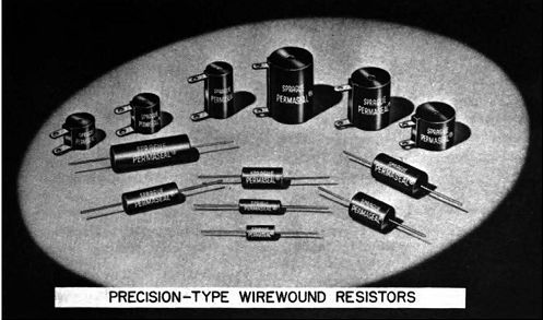
Fig. 2-4. Wirewound resistors, precision type.
------------ TABLE 2-4 Precision Wirewound Resistors

MISCELLANEOUS FIXED RESISTORS
Carbon-film resistors. Carbon-film resistors are made by dc positing a thin layer of carbon on a ceramic rod or tube. The thickness of the film is varied to give the desired total resistance, and the thickness range in general use is between 0.00001 and 0.00000001 inch. Terminals are made by coating the ends with graphite or conductive paint or by plating the ends with metal.
Resistances up to several thousand ohms can be obtained by control of film thickness. Higher resistance values are obtained by cutting a continuous spiral through the film over the full length of the tube. The remaining carbon is thus in the form of a band wound around a ceramic core. Controlling the width of this spiral provides a means of obtaining the desired total resistance. High quality commercial types are coated with resin over which is placed a baked-on, moisture-resistant coating. Hermetically sealed types have an outer ceramic shell to seal out moisture and air and to give additional mechanical protection.
Advantages of carbon-film resistors are that they have negligible voltage coefficient, very low temperature coefficient, and excellent frequency-response characteristics up to 30 mhz. They rep- resent a good compromise between composition resistors and precision wire-wounds. Resistors of 200 ohms have a temperature coefficient of about - 0.025% resistance charge per deg. C. For resistors of 10 megohms this change is in the order of - 0.05%. A ¼-watt, 1% resistor has a body about 1 inch long and ¼ inch in diameter. The resistor may be operated at 1 watt, but the tolerance then widens to 5%. A ½-watt, 1% resistor is about 2 inches long and ¼ inch in diameter and may be operated at 2 watts with 5% accuracy.
As this guide goes into publication, new manufacturing techniques make available carbon-film resistors with a 1% tolerance in power ratings of ½, 1, and 2 watts and with resistances from 25 ohms to 30 megohms. The approximate body sizes for these power ratings are ¾ by 3/16, 1 by 5/16, and 2 by 5/16 inches respectively.
Boron-carbon resistor. Boron-carbon resistors are made in the same general manner as the carbon-film type and are available in similar resistance, power, and tolerance ratings. Their advantage is an even lower temperature coefficient. At a resistance of 200 ohms, the temperature coefficient is one-third that of carbon film, and at 1 megohm the coefficient is one-half that of carbon film.
Metal-film resistor. Metal-film resistors have the same general construction as carbon-film resistors except that the film consists of metal or metal alloy. Through the use of suitable alloys, temperature coefficients lower than those for carbon or boron carbon can be obtained. Available power and tolerance ratings are equivalent to those for carbon-film types, and resistance values from I ohm to I megohm can be obtained.
High-voltage, high-power resistor. Use of the techniques for forming a spiral of resistance material on a ceramic tube has led to the development of resistors with good stability at high resistance values. Since materials with low resistivity can be made into resistors with long conduction-path length, high voltage can be applied, while low voltage per unit length is maintained. Resistors with a 2-watt, 5000-volt peak rating are available from 2500 ohms to 250 megohms in a body size of l¾-inches long by 5/16 inch in diameter. Resistors with a 90-watt, 100,000-volt peak rating are available from 1 megohm to 20,000 megohms in a body size of 20 inches long by 2 inches in diameter. Tolerances of 5, 10, and 15% are available.
VARIABLE RESISTORS CONSTRUCTION
Basic components. The basic components of the most widely used types of variable resistors were shown in Section 1, Fig. 1-3.
Although the shapes and sizes of the various parts may vary with the wattage rating and with the particular production techniques of the various manufacturers, the general arrangement is nearly always the same. The only fundamental differences are in the types of resistance elements used. Figure J-3 (B) shows construction with a wirewound resistance element, and (C) shows the same with a composition element. Both constructions consist of a base, a resistance element with a terminal at each end, a sliding contact arm connected to the center terminal, a rotatable shaft fastened to the contact arm, a threaded bushing, and a cover. The shaft can be turned so that the contact arm can be set to any desired portion of the resistance element. With different settings of the shaft, there are different resistances between either end terminal and the contact-arm terminal. The details of construction vary with the variable resistor wattage ratings. Those with ratings lower than 2 watts generally are adaptable to the mounting of a supplementary switch or additional variable resistors, as will be considered later. As is the case with fixed resistors, there are a limited number of different wattage ratings available for variable resistors.
The most common ratings are 0.2, 0.25, 0.5, 2, 4, 7, 25, 50, 150, and 300 watts.
Composition element. There are two basic forms of composition elements. In one type the material used is similar to that employed in fixed composition resistors. This material is pressed to the required shape and mounted upon the base or is pressed into a shaped depression in the base. The total resistance is con trolled by varying the proportions of the mixture components, as in the case of fixed composition resistors. In the other type a base of insulating material is made to the required size and shape and is coated with composition of the formulation and thickness required to give the desired total resistance.
Wirewound element. There are three basic types of wirewound elements. One type, generally used in variable resistors with power ratings below 5 watts, consists of a Rat strip of insulating material with resistance wire wound around it in a ·single layer, with spaces between the turns. After winding, the form is bent to the required shape and attached to the base. In the second type the wire is wound around a ceramic form of the final shape desired. In this type, a ceramic protective coating is generally used instead of a metal cover, and this construction is usually found only in vari able resistors with power ratings above 25 watts. In the third type, the wire is wound on a flat metal strip, usually aluminum, with a layer of flexible insulation, such as asbestos, between the wire and the strip. This element is then bent to shape and mounted upon a thick metal base. Only a thin layer of heat-resistant insulation is used, so that heat from the resistance wire is easily conducted away. This construction is usually found only in variable resistors with power ratings above 100 watts.
----------------------
TABLE 2-5 Variable Resistor
Composition
Description: Wattages: Body size: Total resistance range:
See text. Design details vary with individual manufactures
0.20, 0.25, 0.5
0.20 watt-¾ in. diam. x ½ in. thick; 300 watt-6 in. diam. X 2¾ in. thick
0.20 watt-1000 ohms to 2.5 megohms; 0.50 watts-500 ohms to 10 megohms
Wirewound
Description: Wattages: Body size: Total resistance range:
See text. Design details vary with individual manufacturers
2. 4, 7, 25, 50, 150, 300 2 watt-1 1/16 in. diam. x 7/16 in. thick; 300 watt-6 in. diam. X 2¾ in. thick 2 watt-6 to 15,000 ohms; 300 watt-1 to 2500 ohms
------------------
Types. Table 2-5 presents a survey of the outstanding characteristics of available composition and wirewound resistors.
Terminology. There are a number of basic terms which are commonly applied to variable resistors. These are illustrated in Fig. 2-5 and described in the following paragraphs.
All of the descriptive terms which are applied to variable resistors are based on the viewpoint of looking straight into the rotatable shaft, as shown in Fig. 2-7. The left terminal is defined as the terminal on the left, and the right terminal is the one on the right in this frame of reference. When the rotatable shaft is turned completely counterclockwise, the contact arm is at the closest possible point to the left terminal, and the resistance between the contact (center) terminal and left terminal is essentially zero.
When the rotatable shaft is turned completely clockwise, the con tact arm is in the closest possible position to the right terminal, and the resistance between the right and center terminals is essentially zero.
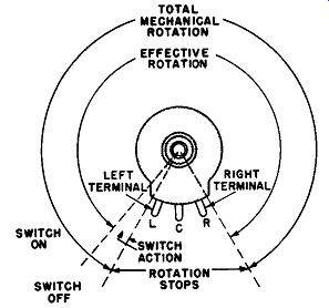
Fig. 2-5. Variable resistor terminology.
The total mechanical rotation is the complete angular rotation through which the shaft can be turned between its fully clockwise and fully counterclockwise positions. A protrusion in the base, called a stop, prevents the contact arm from being turned past the determined limit of rotation. The effective rotation may be defined as the total angular rotation of the shaft which is effective in producing a change in resistance between the center terminal and either the left or right terminal.
In standard variable resistors, the effective rotation is essentially identical to the total mechanical rotation and is usually in the region of 310°. If the variable resistor has a switch mounted on it, as is commonly the case for volume controls in radios and television sets, the total mechanical rotation is increased about 20° without increasing the effective rotation. When the shaft is turned completely counterclockwise, the switch contacts are open, and the resistance between the center and left terminals is essentially zero. As the shaft is turned clockwise, this resistance remains at zero while the switch mechanism is going into operation. At approximately 20° of clockwise rotation the resistance is still zero and the switch contacts snap closed. This is the point at which effective rotation begins, since any further clockwise rotation causes an increase in resistance between the two terminals.
MOUNTING PROVISIONS
Types. There are two types of mounting provisions in common use with variable resistors. Most small variable resistors, usually those below 150 watts in power rating, have what is known as the single-hole mounting. The encased resistor is mounted by means of its threaded bushing through a single hole in a panel or bracket as shown in Fig. 2-6 (A). The standard thread used for this purpose is ¾-32 NEF-2. The other type of mounting is known as the three hole mounting and is generally used with variable resistors over 150 watts in power rating. In this type, shown in Fig. 2-6 (B), the shaft goes through the center hole of the case, but there is no threaded bushing. Fastening is accomplished by means of screws through two side holes. The screws are threaded into holes tapped into the resistor base and tightened. Many variable resistors have a non-turn device, which is a pin or tab projecting from the base.
A hole is drilled into the panel or bracket, and the projection in the base enters the hole. This arrangement prevents the resistor case from turning when torque is applied to the shaft at either extreme of its mechanical rotation.
Shaft types. A wide variety of shaft types has been developed to suit the various ways used to turn the shaft, by knob or other device. The types of shafts and accessories in most common use are shown in Figs. 2-7 through 2-9.
VARIABLE RESISTOR MOUNTINGS
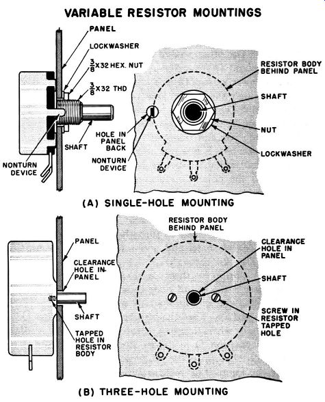
Fig. 2-6. (A) SINGLE-HOLE MOUNTING ( B) THREE-HOLE MOUNTING
In military equipment there are three standard types of shafts.
Simplest of these is the round shaft shown in Fig. 2-7 (A). A knob is .attached to the end of this shaft by means of a setscrew which bites into the surface. The disadvantage of this method is that the knob may slip when the shaft is forced against either limit of its mechanical rotation. The flatted shaft, shown in Fig. 2-7 (B), eliminates knob slip, since the setscrew protrudes down through the wall of the knob. The relationship between the positions of the flat and the contact arm of the variable resistor is standardized as shown in (B). In certain applications, the adjustment of a vari able resistor is intended for use by the equipment manufacturer and by service technicians rather than by the equipment operator. Well-known examples of this are the variable resistors located at the rear of a television set. In such cases, a slotted shaft, as shown in Fig. 2-7 (C), is used. No knob is attached to the end of the shaft, a screwdriver being used instead. The relationship between the slot and contact arm positions is as shown in Fig. 2-7 (C). Variable resistors supplied for commercial equipment frequently are equipped with the types of shafts just described. however, there is a broad selection of special flats, slots and serrations available. Their purpose is to permit rapid attachment of knobs by mass-production techniques. Instead of being attached by means of setscrews, knobs for commercial equipment often are merely pressed onto the shaft and are held in place by means of springs and friction devices in the knob which grasp the special surface.
A special type of variable resistor which is very useful for repair work is the attachable shaft type, one example of which is shown in Fig. 2-8, together with an assortment of available shafts.
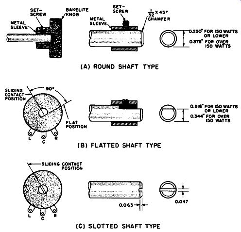
Fig. 2-7. Military standard shaft types. (A) Round. (B) Flatted. (C) Slotted.
(A) ROUND SHAFT TYPE (B) FLATTED SHAFT TYPE (C) SLOTTED SHAFT TYPE
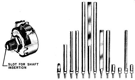
Fig. 2-8. Commercial variable resistor shaft types. (A) One technique of coupling
selected shaft. (B) A selection of available shafts.
This resistor has a short shaft provided with a deep slot into which the selected attachable shaft can be inserted. The added shaft is held to the resistor shaft by means of a split washer which clamps into a groove common to both shafts. In another type, the end of the added shaft has a knurled section which is forced into a hole in the resistor shaft, and friction holds the two together.
Another variable resistor arrangement which is often found is the tandem unit shown in Fig. 2-9 (A), this unit containing three variable resistors. In this arrangement a simple shaft can be used to control the sliding contact of two or more variable resistors and a switch. If independent control of two functions is required, the concentric shaft type, shown in Fig. 2-9 (B), is used. The latter type is used in combination controls, such as the volume-contrast control on TV sets, used when there is limited panel space for controls. Both the tandem and the concentric shaft types are avail able on order from manufacturers. The various components of these units are also available separately, so that repairmen can conveniently construct replacements for damaged units.
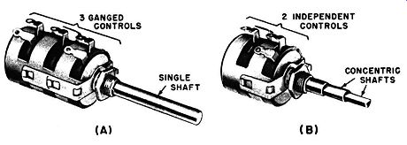
Fig. 2-9. Multiple variable resistor units. (A) Three variables controlled
by single shaft. (B) Two Independent variables with concentric shafts.
CIRCUIT CONNECTIONS
Variable resistors of either the composition or wirewound type are connected into electrical or electronic circuits in either the rheostat or potentiometer arrangement.
Rheostat connections. In the rheostat arrangement shown in Fig. 2-10 (A), one terminal of the resistance element and the terminal of the movable contact arm are connected into the circuit.
RHEOSTAT CONNECTIONS
(A) BASIC CONNECTION ( B) "OFF" POSITION CONNECTION
(C) CONNECTION FOR PROTECTION AGAINST OPEN CIRCUIT
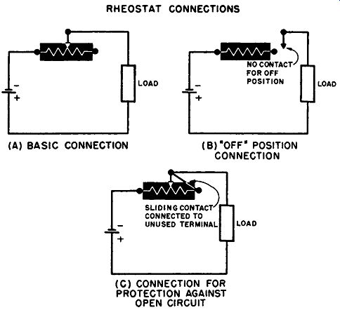
Fig. 2-10. (A) Rheostat connection, (B) Rheostat with "off" position.
(C) Connection for un-used terminal.
By moving the contact arm, the resistance between the two terminals can be varied from zero to the maximum value of the resistance element. Depending upon which terminal of the resistance element is used, the resistance in the circuit can be made to increase or decrease as the shaft is rotated clockwise. Since only two of the terminals are used, one of the terminals of the resistance element can be eliminated completely. In some cases the contact arm can be turned past the end of the resistance element, as shown in Fig. 2-10 (B), so that there is an "off" position in which there is no connection between the two wired contacts. With three terminals it is common practice to connect the unused terminal to the con tact arm, as shown in Fig. 2-10 (C). This provides protection against a condition of infinite resistance (open circuit), should the contact arm fail to maintain proper pressure against the resistance element.
Instead the total resistance of the element enters the circuit the moment the contact fails.
Potentiometer connections. In the potentiometer circuit arrangement the three terminals are connected as shown in Fig. 2-11.
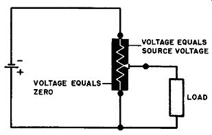
Fig. 2-11. Potentiometer connection.
A source of ac or dc voltage is connected across the two ends of the resistance element. The output, or load, is connected across the terminal of the contact arm and one end terminal. Turning the shaft changes the amount of resistance between the contact arm and each of the end terminals so that the output voltage can be varied from zero to the full value applied across the two outside terminals.
RESISTANCE TAPERS
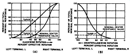
Fig. 2-12. Variable composition resistor tapers. (A) Clockwise tapers A and
C. (B) Counterclockwise taper.
Un-tapered resistors. If the resistance element is constructed in a uniform manner, the resistance between either end terminal and the center terminal will vary as shown in curve A, Fig. 2-12 (A), as the shaft is turned. The result is that essentially 25% of the total resistance will exist between these terminals when the contact arm is turned 25% of its effective rotation from the end terminal.
When the rotation is 50 and 75%, the resistance between the end and center terminals will be 50 and 75%, respectively, of the total.
Thus the resistance variation is uniform with the degree of rotation, and the plot of resistance against rotation is essentially a straight line. This type of resistor is known as an un-tapered or linear resistor. Although the term is not technically correct, this arrangement is frequently known as a linear taper or A taper.
Tapered resistor. In certain applications it is not required that resistance vary in a linear manner as the shaft is turned. Instead it is more important that the effect being controlled (such as the loudness of sound from a loudspeaker, the speed of a motor, or the brightness of a bulb) be proportional to the degree of shaft rotation. In such cases the desired result can be obtained by pro viding for a resistance change which is not proportional to the degree of shaft rotation. Such a resistor is known as a tapered resistor.
There are a number of tapers available from different manufacturers, but the most commonly used types are the clockwise and counterclockwise tapers. The clockwise taper for composition resistors is shown in curve C of Fig. 2-12 (A). When the resistance is measured between terminals L and C, the resistance varies as shown. During the first 30% of clockwise rotation, the resistance between the two terminals shows an imperceptible rise above zero.
At about 50% of clockwise rotation the resistance between the two terminals is approximately 10% of its total value. Further clock wise rotation causes a very rapid increase to the total value. In military specifications this resistance variation is known as a C taper, and a commercial name sometimes used is the left-hand taper.
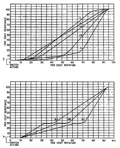
Fig. 2-13. Commercial variable composition resistor taper charts.
The counterclockwise taper for composition resistors is shown in Fig. 2-12 (B). In military specifications this type is known as an F taper, and commercially it is often known as the right-hand taper.
When the resistance is measured between the right and center terminals and the contact arm is turned counterclockwise, there is no significant resistance rise above zero for the first 30% of rotation. At 50% rotation the resistance is at 10% of its total value.
Further rotation causes a rapid increase to the total value. Examples of commercial variable resistor taper charts are shown in Fig. 2-U. In molded composition resistors the taper can be produced by varying the proportions of the conductive and nonconductive materials at various portions of the resistance element. The same effect can also be obtained by using a uniform mixture and varying its thickness or width along the length of the resistance element.
In wirewound variable resistors, the un-tapered type is made by using uniform wire and uniform turn spacing along the length of the resistance element. A wirewound resistance taper can be produced by changing the turn spacing, by changing the characteristics of the resistance wire, or both. In wirewound resistors the resistance variation is not as smooth as in the composition type, as shown by the typical examples of the wirewound A, C, and F types in Fig. 2-14.
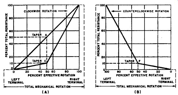
Fig. 2-14. Charts of variable wirewound resistor tapers. (A) Clockwise tapers.
(b) Counterclockwise tapers.
SPECIAL-PURPOSE RESISTORS THERMISTORS
Thermistors are thermally sensitive resistors. While most materials increase in resistance with rising temperature, the resistance of a thermistor drops sharply. The resistance drop is in the order of 4% for every degree Centigrade rise in temperature. For this reason, thermistors are useful in applications involving temperature measurement and control.
When an electric current is passed through a thermistor, its temperature will rise. The speed and extent of the temperature rise depend upon the magnitudes of the current and resistance, plus the thermal mass of the thermistor and the heat dissipation facilities provided. Since a decrease in resistance accompanies the temperature rise, these various characteristics make it possible to use thermistors in voltage, current, and power control circuits and in time-delay devices. If a thermistor conducting an electric current is placed in a stream of liquid or gas, or in a container, the rate of heat dissipation is determined by the composition and flow rate of the surrounding medium. Changes in the composition or flow rate change the temperature of the thermistor and cause significant variations in the electric current These current variations can be calibrated to indicate the composition, flow rate, pressure, or level of the medium in which the thermistor is placed.
Thermistors are made of a mixture of semiconductor oxides; mainly the oxides of nickel, manganese, and cobalt. The proportions of these materials are varied to produce the desired characteristics.
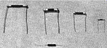
Fig. 2-15. Rod-type thermistor.
During manufacture the mixture is combined with a binding material and formed into rods, discs, washers, or beads.
Heating in an oven produces a finished material which has the appearance of a ceramic. Leads or terminals are bonded in place.
Bead thermistors are generally available with a glass coating or encased in a glass envelope. The bead length and diameter may be as small as 0.01 and 0.005 inch, respectively and as large as 0.5 and 0.2 inch, respectively. Available resistances at 25-C cover the range from 1000 ohms to above 10 megohms.
Disc thermistors are available in diameters ranging from 0.2 to 0.6 inch. Washer-shaped units generally have a diameter of 0.75 inch. Both types are available in thicknesses ranging from 0.05 to 0.5 inch. Available resistances at 25-C cover the range from 10 to 1000 ohms. Thermistors of these types can be stacked together to male various series and parallel arrangements, and their form makes them convenient for mounting.
Rod-type thermistors (see Fig. 2-15) are used when high resistances are required. Lengths and diameters range from 0.25 and 0.05 inch, respectively, to 2 and 0.1 inch, respectively. Resistance values range from 1000 ohms to 100,000 ohms.
VARISTORS
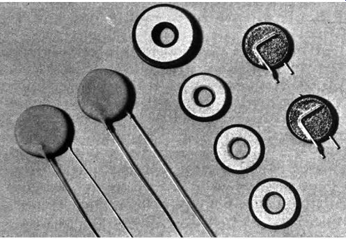
Fig. 2-16. Washer-and disc-type varistors.
Varistors are resistors which exhibit a significant change of resistance with applied voltage. There are two types of varistors.
One type exhibits a large change of resistance when there is a change in the polarity of the applied voltage. Units of this type are commonly known as "solid-state" rectifiers and include units such as selenium and copper-oxide rectifiers and silicon and germanium diodes. Such devices are amply described in specialized textbooks, and their characteristics are so widely different from units commonly known as resistors that they will not be considered here.
The second type of varistor exhibits a resistance which changes with the applied voltage. In the case of ordinary resistors the relationship between voltage, current, and resistance follows Ohm's law. In the case of a varistor the relationship is:
E" R=--. I
The value of " is a constant which depends upon the varistor manufacturing process. Units with " values in the range of from 3 to 5 are commonly available, and some manufacturers produce varistors with " values in the range of from 2 to 7. Because of the unusual characteristics of varistors, an increase in the applied voltage causes an increase in current which is significantly higher than in the case of a standard resistor. Variable resistance characteristics of this type make varistors uniquely suited for use as voltage and current regulators.
Essentially the same process is used in the manufacture of most commercial varistors. Silicon carbide particles are mixed with purified clay and water. The mix is pressed into washers, discs or rods; and these units are placed in a high-temperature furnace.
After the firing process, metal electrodes are sprayed on, and connecting leads or terminals are attached. A coating of water proofing compound is added.
Discs and washers are the varistor shapes commonly avail able (see Fig. 2-16). Diameters generally range from 0.5 to 1.0 inch, and thicknesses range from 0.025 to 0.2 inch. Four significant ratings are used to describe the functional characteristics of a varistor. Power ratings generally available range from 1 to 10 watts.
Values of" are generally in the range of from 3 to 5. Recommended current ranges for a varistor may be as low as 0.05 to 10 ma or as high as from 20 to 500 ma. Because of the change of resistance with voltage, no resistance rating is listed. Instead, a voltage is listed for a specified current. Typical voltage/current ratings may be as low as 1 volt at 1 ma or as high as 50 volts at 1 ma.