AMAZON multi-meters discounts AMAZON oscilloscope discounts
CAPACITANCE
Basic characteristics. When two metal plates are placed close together, as shown in Fig. 3-1 (A), the combination exhibits certain electrical effects which are known as capacitance. The outstanding characteristic of the combination is that it opposes any change in voltage across its plates.
This characteristic may be broken down into three effects which are closely related. First, a measurable time elapses before the two plates acquire the voltage difference of a voltage source connected across them. Second, the two plates maintain this acquired voltage difference for some time after the voltage source is disconnected. If there were no leakage conduction through such media as the air or other insulating material separating the plates, and if there were no other path of electrical conduction between the plates, the acquired voltage difference would be maintained indefinitely after the source of emf is disconnected. Third, if the two plates are connected together through a resistance, there is a measurable time delay before the voltage difference between them drops to zero.
These effects of capacitance are due to the fact that similar electric charges repel each other, and unlike electric charges attract each other. Before any voltage is connected across the plates of a capacitor, all of the atoms in both plates are electrically neutral.
That is, they contain an equal number of protons and electrons.
When the voltage source is connected across the plates, the negative terminal forces additional electrons onto the plate to which it is connected, and that plate becomes negatively charged. The positive voltage terminal attracts electrons away from the plate to which it is connected and leaves that plate positively charged.
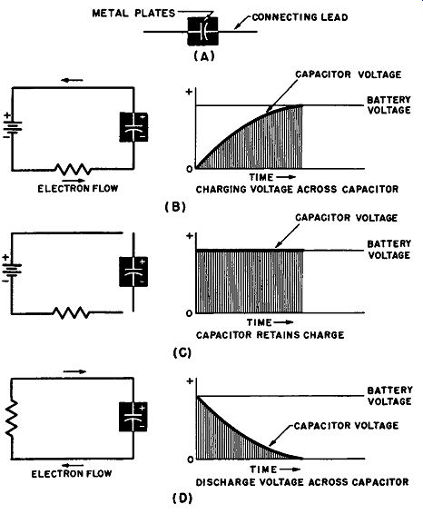
Fig. 3-1. Capacitor characteristics. (A) Basic form. (B) Delay in capacitor
charge. (C) Capacitor retains charge. (D) Delay in capacitor discharge.
The charges on the two plates are equal but of opposite polarity.
Thereafter, since electrons repel each other, the electrons on the negative plate oppose the action of the voltage source in forcing more electrons toward that plate. And, since protons attract electrons, the protons on the positive plate oppose the action of the voltage source in attracting electrons from that plate.
Although opposition is offered to the charging effects of the voltage source, the voltage across the two plates eventually becomes equal to that of the source; and at that time no further charging effect takes place. However, the positive and negative charges on the two plates attract each other through the space between the plates, setting up a strong electrostatic field between the plates.
Since work is expended in charging the capacitor, that work appears in the form of potential energy stored in the capacitor.
This potential energy is released in the form of current flow when a circuit is connected across the plates.
Capacitive reactance. When the voltage source connected across the capacitor is a d-c source, current flows through the connecting wires only during the time the capacitor is charging. If a source of a-c voltage is connected across the capacitor, the charge on each plate continually increases, decreases, and reverses its polarity.
The result is that an ac current continuously flows through the connecting wires. The charging and discharging of the capacitor plates offers opposition to the flow of current in the circuit, and this opposition is known as capacitive reactance.
The charge that can be stored in a capacitor increases as the area of the plates is increased, as the distance between the plates is decreased, and as materials of better insulating quality are placed between the plates. Details concerning these relationships will be considered shortly. Capacitive reactance is infinitely large when a dc voltage source is connected across the plates, and this reactance decreases as either or both the capacitance of the capacitor and the frequency of the applied voltage are increased.
In electrical and electronic applications there is frequent need for a unit in which any particular desired amount of capacitance is lumped into the form of a single unit which is convenient to use.
Such a unit is called a capacitor or a condenser. Although capacitance is the preferred term applied to the electrical effects exhibited by a capacitor, the term capacity is in popular usage.
BASIC FACTORS DETERMINING CAPACITANCE
Basic construction. The basic form of a simple capacitor is shown in Fig. 3-2. It consists of two metal plates, with attached terminals or leads, and the two plates are separated by an insulating material or "dielectric." The dielectric material commonly may be treated paper, mica, oil, ceramic, air, compressed gas, or a vacuum.
The total capacitance of any particular construction is basically determined by the type of dielectric material used, the area of the plates, and the distance between the plates-although there are other important factors which will be considered later.
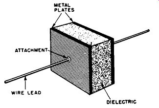
Fig. 3-2. Basic capacitor construction.
Dielectric constant. Capacitance increases as the area of the plates is increased, as the distance between the plates is decreased, and as insulating materials of higher dielectric constant are used.
The term dielectric constant is defined on the basis of a comparison between two capacitors of identical plate area and plate separation, with the material in question separating the plates of one capacitor, air separating the plates of the other capacitor. Dielectric constant is thus defined as the ratio between the two total capacities. Since mica has a dielectric constant of about 7, a mica capacitor has 7 times the total capacitance of an identical capacitor with air as the dielectric material. The dielectric constants of several common materials are listed in Table 3-1.
TABLE 3-1
-----------
Material | Dielectric constant
Crown glass | Plate glass | Mica ( U.S. clear)
Kraft paper, dry Paraffin Mineral oil Fused quartz Unglazed porcelain
------------
The basic relationship between these various factors and the total capacitance is:
KA c---
- 4,,.d '
.... where K is the dielectric constant, A is the area of one of two identical plates, and d is the distance between the plates.
The term "dielectric constant" is somewhat of a misnomer, since it is not a true constant. K varies with temperature and with the frequency and amplitude of the voltage applied across it.
CAPACITOR TYPES
In electrical and electronic equipment, it is very often necessary to use capacitors for coupling the signal between amplifier stages, bypassing the signal away from various vacuum-tube elements, decoupling stages, filtering ripple from power supplies, forming complex signal filter networks, and forming tuned circuits for r-f oscillators and amplifiers. In these various applications the equipment designer has a choice of three broad groups of capacitor types: fixed, adjustable, and variable. These will be introduced here, and details concerning the wide variety of commercial types will be discussed in Section 4.
Fixed capacitors. A fixed capacitor has its total capacitance determined at the time of manufacture, and there are no pro visions for changing this predetermined value. The designer selects the total capacitance and other required characteristics from a wide selection of types and values. Figure 3-3, (A) through (D), shows the paper tubular, mica, electrolytic, and ceramic types. These are the most common types, but there are a number of other special types which will also be considered in Section 4.
Adjustable capacitors. There are applications, such as certain types of tuned circuits, in which the exact value of capacitance required in the circuit cannot be predicted or controlled with the required accuracy. In such applications, it is helpful to have available a capacitor which can be adjusted to the exact required value when the equipment is aligned after assembly. Adjustment by the equipment user is unnecessary, although a later adjustment may have to be made by a service technician during equipment servicing. Since the capacitor does not require frequent resetting, no special pains are taken to make this adjustment particularly convenient, and the range of adjustment is generally quite small.
Four common types of adjustable capacitors are shown in Fig. 3-4. Part (A) shows a type with mica dielectric, the total capacitance of which can be changed by compressing or expanding the distance between the plates. Fig. 3-4 (B) shows a type with
ceramic dielectric, the total capacitance of which can be changed by rotating a movable semicircular plate with respect to a fixed plate of similar shape. Rotating the plate affects the total opposing area between the plates and thus adjusts the total capacitance.
Figure 3-4 (C) shows a type with air dielectric, which is adjusted by rotating the metal plates. Part (D) shows a type with air dielectric which is adjusted by changing the distance between the plates. Details of these and other adjustable capacitors will be considered in the next section.
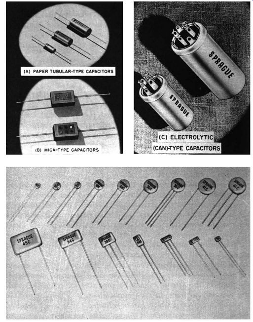
Fig. 3-3. Common types of fixed Capacitor. (A) Paper tubulars. (B) Mica. (C)
Electrolytic. (D) Ceramic.
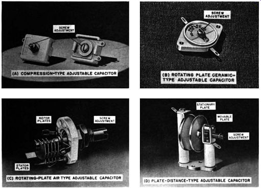
Fig. 3-4. Adjustable capacitor. (A) Compression type; (B) Rotating-plate ceramic
type. (C) Rotating-plate air type. (D) Adjustable-plate distance type.
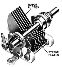
Fig. 3-5. Variable capacitor.
Variable capacitors. In a number of applications the equipment operator must tune his equipment by changing capacitance over a fairly wide range. Figure 3-5 shows one type of variable capacitor which is commonly used for this purpose in most home radio receivers. Total capacitance is changed by varying a set of movable plates which intermesh with-but do not contact--a set of fixed plates. Because such rotation changes the total opposing area between the fixed and movable plates, the total capacitance is changed. Care is taken in the design and manufacture of these capacitors to secure ease and smoothness of rotation along with an accurately predictable variation throughout the full range of rotation. Details of different types of variable capacitors will be considered in Section 4.
CAPACITOR CHARGE AND ENERGY
Charge. The capacitance of a capacitor is basically determined, as mentioned previously, by the area of the plates, the distance between the plates, and the dielectric material used. The number of excess electrons that can be held upon the negatively charged plate of any given capacitor depends upon the capacitance and the applied voltage according to the relationship: Q=CE, where Q equals the charge expressed in coulombs, the quantity C equals the capacitance expressed in farads, and E equals the applied voltage.
One farad of capacitance is that amount of capacitance which will accumulate one coulomb of charge when the applied voltage is equal to one volt. Capacitors normally found in electronic equipment generally range in capacitance from 1 micro-micro-farad (1 u.u.f) to 1000 microfarads (1000 µf). Thus few capacitors found in commercial equipment have a capacitance of more than a few thousandths of a farad.
Energy. Since the voltage source must expend energy while it is forcing electrons to accumulate on the plates of a capacitor, work is done according to the relationship:
• A coulomb is defined as the unit of electrical charge which results from the accumulation of 6,M0,000,000,000,000,000 (or 6.3 x 10^8) excess electrons.
Capacitance (farads) X voltage2 Work (joules)= 2
• Since power is defined as the time rate of doing work, the average power expended in charging the capacitor is expressed by the relationship:
cv2 Power (watts) = --- 2T (sec)
When an ac voltage is applied across the capacitor, the power expended is indicated by:
P= CV,,2F,
where the power P is expressed in watts, the frequency F in hz, and V, indicates the peak applied voltage.
CONSIDERATIONS AFFECTING CAPACITOR SELECTION
In the preceding discussion it was mentioned that other factors besides plate area, plate separation, and dielectric material affect total capacitance. These factors include frequency, temperature, and age. Other factors affecting the application of any particular capacitor construction are the "strength," dc leakage, power factor, polarization, and absorption characteristics of the dielectric material. Because of these various characteristics, capacitance cannot be regarded as a constant determined only by construction but as a quantity which is affected to a significant extent by the particular application.
As is the case with resistors, an equipment designer cannot select a capacitor simply on the basis of the total capacitance he requires. Capacitors, like resistors, cannot be manufactured to the exact total capacitance values required and are generally supplied with an indication of the tolerance to which they have been made.
In addition, the factors mentioned in the previous paragraph also affect capacitor application. Thus the equipment designer must determine what capacitance effects will take place in each specific application. He must decide which of these effects are undesirable and must be compensated for and which effects are unimportant to the specific application. After such considerations are made, he has a basis for selecting the lowest-cost capacitor having acceptable characteristics. The paragraphs which follow review the major considerations affecting capacitor selection, and Section 4 reviews the types and features of commercially available capacitor.
Dielectric strength. The ability of the capacitor dielectric to resist breakdown when voltage is applied across it is known as dielectric strength. This quality is usually expressed in terms of kilovolts percentimeter, or in volts per mil, of dielectric thickness.
Dielectric strength is not a quantity that is simply determined from the type of material and its thickness. There are temperature, resistance, and frequency effects which also must be considered.
Dielectric strength usually decreases with temperature rise, since the resistance of most capacitor dielectric materials decreases with temperature rise. Dielectric strength is not uniform throughout the structure of a typical piece of dielectric material. Localized variations in the composition and structure of the material result in regions of low resistance. Current leakage is then concentrated in these sections, which results in localized heating and a greater tendency to break down. Because of these effects, testing the ability of a capacitor to resist breakdown requires both a brief application of high voltage and a long period of low-voltage application. In addition, a measurement is made of the steady current that flows when a constant direct voltage is applied across the capacitor, and this is known as direct leakage current.
These effects are not the only ones involved in checking capacitors. Dielectric strength also generally decreases with increasing frequency of the applied voltage and with age. Capacitor selection requires a careful consideration of those of the mentioned factors which are appropriate to the specific application.
The higher the strength of the dielectric used, the smaller is the distance needed between the plates to resist breakdown at any particular operating voltage. Thus, when materials with high dielectric strengths are used, greater capacitance can be obtained in a given capacitor size. The effects of this will be seen in the next section in comparing the physical sizes of different types of capacitors of the same total capacitance.
Dielectric absorption. When a capacitor is connected across a dc source, there is a surge of current as a charge builds up.
Following that is a small, steadier current flow which slowly decreases. This additional current flow does not add to the charge on the plates, but it is absorbed by the dielectric. This dielectric absorption produces a strain in the dielectric material known as dielectric polarization, and represents additional energy stored in the capacitor.
If the capacitor leads are touched together, the electrons from the negative plate quickly flow through the leads to the positive plate, thus apparently reducing the charge to zero. In the case o a large capacitor, such a large current flow may take place than a spark may be seen at the point where the leads touch, and a loud snapping sound may be heard. If the leads are separated and touched together again a few second later, an additional but weaker current flow may be heard and seen. This second discharge represents the energy that was absorbed by the dielectric and which has gradually been released in the form of additional charge on the plates. In the case of a capacitor with a large amount of solid dielectric, the dielectric absorption may be so large that several additional secondary discharges may be obtained.
Capacitors which exhibit relatively large amounts of dielectric absorption tend, more than other capacitors, to accumulate les and less charge as the frequency of the applied voltage is increased At radio frequencies, and at those slightly below, the rapid reversal of the dielectric polarization cause heating of the dielectric and represent considerable power loss in the capacitor.
CAPACITOR LOSSES
Power losses in a capacitor are due to dielectric losses and leakage. The effect of these losses can be evaluated by consideration of the phase difference and power factor.
Dielectric losses and leakage are defined with respect to what is termed the geometric capacitance. A capacitor will accumulate greater charge when applied voltage is at a low frequency than when it is at a higher frequency. Thus, the capacitance of a practical capacitor decreases with increasing frequency, and its capacitance at infinite frequency is called its geometric capacitance. Though not completely correct, the term useful capacitance presents a more descriptive concept and may be used instead. If the capacitor had a perfect dielectric material, its capacitance would remain the same at all frequencies; its useful capacitance would then be equal to the capacitance at the lowest frequency.
Figure 3-6 (A) shows the equivalent circuit of a capacitor with both dielectric absorption and d-c leakage. In the diagram C represents the useful capacitance, with the d-c leakage resistance R1 connected in parallel, and with the dielectric absorption indicated by the combination of R, and C, also connected in parallel with the useful capacitance. The equivalent circuit shown in Fig. 3-6 (A) is commonly resolved to the form of a capacitor with a series fixed resistor, which represents all losses, as shown in Fig. 3-6 (B).
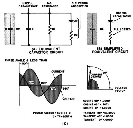
Fig. 3-6. Basic capacitor characteristics, (A) Equivalent circuit. (B) Simplified
equivalent circuit. (C) Power factor and Q. (A) EQUIVALENT CAPACITOR CIRCUIT
; (B) SIMPLIFIED EQUIVALENT CIRCUIT
The characteristics of phase angle are covered in texts on basic electricity and electronics and will be reviewed here only very briefly to define capacitor power factor. When an ac voltage is applied across a capacitor, the current through the capacitor leads the voltage by an angle 6 shown in Fig. 3-6 (C), which is called the phase angle and which may approach but never exceed 90 . The power factor is equal to the cosine of the phase angle as shown by the equation:
Power factor= cos (J •
The voltage across the capacitor E and the a-c Row through the capacitor I together with the power factor can be used to define the power loss in the insulating material:
Power loss = El cos (J •
The power factor is a term which takes into account all of the power losses in a capacitor. Most of the phase difference with respect to the ideal value of 90° is due to dielectric absorption.
DC leakage through the dielectric, represented by R1 in Fig. 3-6(A) does add to the phase angle but, for a good capacitor, is not significant at high frequencies. If the total power loss in watts is measured, the power factor can be expressed in terms of a percentage by the relationship:
wx 10^6
Cos (J (percent) = --- 2,,f CE2
where W equals the power loss in watts, f equals the frequency of the applied voltage in hz, E equals the rms voltage applied, and C equals the capacitance expressed in p.f.
There is a factor called Q which can be used as a quantitative figure of merit for comparisons of various capacitors. Q is defined with respect to the current and voltage vector diagram shown in Fig. 3-6 (C). Q is equal to the tangent of the angle between the voltage and current vectors at any particular specified frequency.
Q can be expressed by the formula: I Q= Rx 2 pi FC ' where R equals the equivalent series resistance (symbolizing losses) in ohms, F equals the frequency in hz, and C equals the capacitance expressed in farads.
The figure of capacitor merit, Q, is referenced to the equivalent series resistance of the capacitor.