AMAZON multi-meters discounts AMAZON oscilloscope discounts
1-1 Function of the Resistive High-Voltage D-C Probe
Most conventional volt-ohm-milliammeter (vom) and vacuum-tube volt meters (vtvm) have d-c voltage measuring ranges which do not exceed 6,000 volts--in fact, many do not exceed 2,000 volts. Such ranges are sufficient for measurement of the low and medium voltages generally encountered in electronic and industrial electric equipment. However, it is frequently necessary to measure the much higher d-c voltages present in some of the circuits in industrial electrical equipment, electro-medical apparatus, radio and tv transmitters, and the horizontal output and high-voltage picture tube circuits of television receivers (see Fig. 1-1A). For example, the typical actual second-anode d-c operating voltages for black-and-white tv picture tubes of various sizes, and for the color picture tubes announced thus far, are as follows: The normal d-c voltage measuring range of a conventional high-resistance vom, and of a vtvm, can be effectively extended to make high-voltage measurements possible through the use of a simple external multiplier resistor of proper value, arranged in a suitable insulated probe body, and connected in series with the input circuit of the instrument. A typical resistive high-voltage probe is illustrated in Fig. 1-1B. While such probes are primarily intended for use with high resistance vom's and with vtvm's, they also have some special applications in connection with oscilloscopes (see Sec. 1-9). The multiplier resistance employed is ordinarily chosen to provide a convenient decimal scale-multiplication factor such as 100-to-1, or 1,000-to-1, so that the d-c scale of the vom or vtvm is direct-reading with the addition of one or more zeros when the probe is used.
1-2. Calculating the Multiplier-Resistance Values
Required for use with a VOM The value of multiplier resistance required to extend the d-c voltage range (usually the highest d-c voltage range of the instrument is extended) of a vom to a desired value may be easily calculated if the sensitivity of the instrument is known, or if the input resistance of the instrument when the range switch is set for that particular d-c voltage range value, is known. The following practical example will illustrate this:

Fig. 1-1. (A) Tv high-voltage circuits where a resistive high-voltage probe
must be used with a vom, or a vtvm, for d-c voltage measurement. (B) Cross
section of a high-voltage d-c probe, and its heavy-duty connecting cable, for
use with a sensitive vom or a vtvm. The insulating probe housing is specially
shaped and constructed to minimize electrical leakage and corona. The full
handle length contains a grounded internal flashover guard shield. A ribbed
external leakage and arc-back barrier is also provided. The long spiral-film
type multiplier resistor in removable cartridge form extends almost the full
length of the probe. Either the pin-plug type termination shown here, or a
standard screw-on mike type (panel) connector for use with most vtvm's may
be provided at the meter end of the connecting cable.
This probe will provide voltage ranges to 60,000 volts de when used with standard vtvm's or high-sensitivity (20,000 ohms-per-volt) vom's. (B) Courtesy: Precision Apparatus Co., Inc.
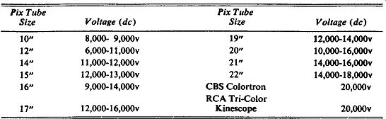
TABLE 1-1. TYPICAL ACTUAL SECOND-ANODE VOLTAGES FOR PICTURE TUBES OF VAR1OUS SIZES
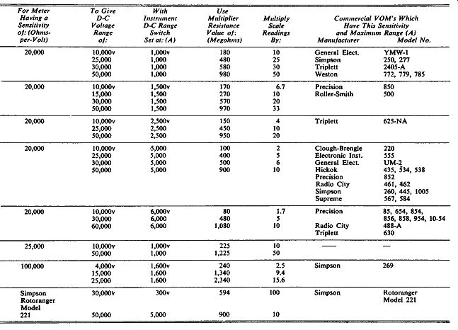
TABLE 1-2. HIGH-VOLTAGE (D-C) MULTIPLIER RESISTANCE SELECTION CHART OR VOM's
--- Compiled from information supplied by Precise Development Corp.
Let us assume that a service-type vom whose sensitivity is 20,000 ohms-per volt and whose maximum d-c voltage range is 6,000 volts is to have this range extended to 30,000 volts, so that all required high-voltage measurements in monochrome and in color tv receiver servicing may be made with it. This is to be accomplished by means of an external multiplier resistor, R, connected in series with it, with the range switch set at the 6,000-volt range position, as shown in Fig. 1-2A. The input resistance, R_M, of the instrument is equal to the full-scale voltage of the range multiplied by the instrument sensitivity in ohms-per-volt. In this particular case, R_M = 6,000 X 20,000 = 120,000,000 ohms, or 120 megohms.
The voltage distribution in the probe-plus-meter circuit will be as shown in Fig. 1-2B. Observe that when the test circuit voltage is 30,000 volts, the meter is to read full scale, so the voltage being applied to input terminals of the meter must be 6,000 volts. This leaves 30,000 - 6,000 = 24,000 volts to appear as a voltage drop developed across the multiplier resistor R. Since this is a simple series circuit, the voltage drops are proportional to the resistance, so
R 24,000 R
-- = ---- or -- = 4 R.u 6,000 RM
Therefore, R = 4 X 120 = 480 megohms.This is the required multiplier resistor value for these particular conditions. When this resistor is used, each reading taken on the 6,000-volt d-c scale must be multiplied by the factor 5 (30,000 + 6,000), to obtain the true voltage.
When selecting and applying resistive high-voltage probes to vom's, it must be remembered that because the input resistance value of a vom is entirely different for each setting of the d-c voltage range switch, the calculated value of the multiplier resistance required to obtain a particular multiplying factor with a specific instrument is the correct one for only the particular range-switch set ting that was considered in the calculation.
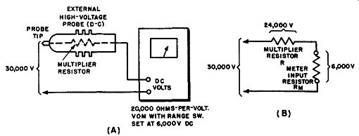
Fig. 1-2. (A) Connection of multiplier resistor in series with vom input circuit.
(B) Voltage distribution in the series probe-plus-meter circuit, for the particular
conditions specified in the text problem.
Table 1-2 is presented here as an aid in the rapid determination of the correct multiplier resistance required to extend the normal specified d-c voltage range of conventional 20,000, 25,000, or l00,000 ohms-per-volt vom's to the higher ranges frequently required in the testing of some high-voltage circuits in electrical and electronic equipment. For added utility, the manufacturer's name and model numbers of popular commercial vom's which fall into each sensitivity-and-range category are also listed. For instrument and range combinations other than those listed in this table, the calculation procedure explained earlier in this section may be used.
1-3. Resistive Loading Effect of Probe-and-VOM Combination
The current drawn from the test circuit by the resistive high-voltage probe and vom combination is a matter of importance when this combination is used for measuring the voltage in high-voltage circuits whose voltage regulation is poor. For example, the voltage regulation of the typical picture-tube high voltage supplies employed in tv receivers is relatively poor. As a result, the out put voltage tends to decrease appreciably (see Fig. 1-3) if the current demand is increased very much percentage-wise above that of the picture tube in normal operation. Consequently, for accurate measurement of the high voltage at the second anode of a picture tube by means of a resistive high-voltage probe and vom combination, it is necessary to make the measurement in such a manner that the current load on the high-voltage power supply of the receiver will not be appreciably greater than the normal beam current of the picture tube. The beam current of most picture tubes of the 17- to 21-inch size group may be considered as being approximately 300 microamperes, for normal brightness.
Let us assume that a conventional 20,000 ohms-per-volt vom having a 6,000-volt d-c range is used in combination with an external 480-megohm resistive high-voltage d-c probe to extend this range to 30,000 volts (see Table 1-2), and that this combination is to be employed to check the second-anode voltage of a 21-inch picture tube. This voltage to be checked will be approximately 14,000 to 16,000 volts (see Table 1-1). If the actual second-anode potential is 16,000 volts, the probe-plus-vom combination (whose total resistance is 20,000 X 6,000 ohms + 480 meg = 600 meg) will cause a current drain of approximately 27 microamperes. Obviously, this nominal additional current drain added to the beam current (approximately 300 µa) of the tube for normal brightness will not appreciably alter the actual second-anode voltage. Accordingly, the measurement may be made by merely applying the measuring circuit to the second-anode terminal and chassis-ground of the receiver.
Fig. 1-3. Measured steady-load voltage regulation characteristic of high-voltage supply for the 16AP4 picture tube. Courtesy: RCA
To investigate the current loading effects further, let us next consider the conditions if a 1,000 ohms-per-volt meter having a top d-c voltage range of 3,000 volts is used for this measurement. A 27-megohm multiplier resistor would be required to extend the range to 30,000 volts, and the current drain imposed by the measuring-instrument circuit would not be 533 µ,a. Since the beam current of the picture tube is considered to be 300 µ,a, it is plain that in this case the appreciable test-instrument current drain would load down the high-voltage power supply very seriously, resulting in a large regulation error if the measurement were made in the conventional manner. More accurate measurement could be accomplished by removing the second-anode lead from the picture tube during measurement (or turning down the brightness control to minimum), so that the current drain of the instrument would be substituted for (instead of being added to) the normal beam current of the picture tube. Of course, greater accuracy is obtained by using a 20,000 ohms-per-volt vom for this purpose, so that the measuring circuit has relatively high resistance.
1-4. Selection of Multiplier-Resistance Values for use with VTVM's
A series multiplier resistor arranged to form an external probe may also be used to extend the d-c voltage measuring range of a vtvm so that the instrument may be used for the measurement of high voltages. However, the behavior of such a multiplier used with a vtvm is different in one respect from that when used with a non-electronic vom.
The circuit arrangement in Fig. 1-4 shows an external multiplier resistor arranged in d-c probe form connected in series with the conventional type of d-c input circuit employed in vtvm's. In order to permit the vtvm to make d-c voltage measurements accurately over a variety of easily selected voltage ranges, a voltage-divider circuit is usually arranged across the input terminals to the instrument, as shown, and a range switch permits a definite proportion of the applied input voltage to be tapped off and applied to the measuring tube and indicating meter. The tube draws no current from the input circuit. Since the full voltage-divider resistance is always in the input circuit and is constant in value regardless of the setting of the range switch, when this input circuit arrangement is employed, an external multiplier resistor will multiply each range of the vtvm by the same factor (for example 100) and hence the same multiplier resistor can be used when any range of the vtvm is employed. By selecting a suitable value of the multiplier resistance for the high-voltage probe, the normal voltage range for each position of the vtvm range switch can be multiplied by a desired amount. A decimal (10, 100, 1,000, etc.) multiplying factor is usually chosen for operating convenience because high-voltage measurements can then always be made on the upper portion of the scale, which provides higher accuracy of indication. In most cases, the multiplier resistance value is selected to provide the desired high-voltage measuring range when the vtvm range-selector switch is set at the highest d-c voltage range of the vtvm.
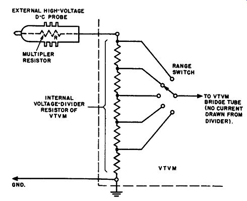
Fig. 1-4. The measuring tube of a vtvm draws no current, and hence the meter
in the vtvm really indicates the voltage drop at any selected point along the
internal voltage-divider resistor, instead of measuring the current through
the instrument, as does a vom. For convenience, the value of the external multiplier
resistor in the resistive high-voltage probe can be selected to multiply each
of the vtvm voltage ranges by a convenient decimal factor, such as 100.
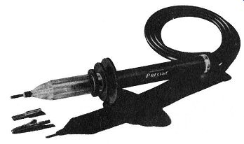
Fig. 1-5. External appearance of a high-voltage d-c probe for use with a vom
or a vtvm, provided with an interchange able conventional tip for probing,.
and an alligator clip for permanent connection to the circuit. The multiplier
resistor cartridge is held be tween a double-spring suspension system inside
of the clear plastic portion at the left. This probe is rated at 30,000 volts
maximum. Courtesy: Precise Development Corp.
The multiplier resistance required to extend the voltage range of a vtvm is calculated in the same general manner as for a vom (see Sec. 1-2). For example, suppose it is required to extend the 500-volt d-c range of a vtvm having 11 megohms input resistance, to 50,000 volts (100 to 1 voltage multiplication). When the test input voltage is 50,000 volts, the voltage applied to the normal vtvm d-c input terminals and l I-megohm input resistance must be 500 volts. A voltage drop of 50,000 - 500 = 49,500 volts must therefore be developed across the multiplier resistor. The value of the latter must be, therefore,
49,500 R =---- '( II= I,089 meg. 500
(Actually, a 1,090-meg multiplier is used to take into account the 1-meg isolating probe usually used with the vtvm. The h-v probe is substituted for the isolating probe, whose purpose is described in Section 2.) If it is desired to measure, say, 19,000 volts with this high-voltage probe and vtvm, the range switch should be set to the 500-volt range. The indication will be 190 volts on the 500-volt scale.
The meter reading is then multiplied by the probe multiplying factor of 100, to give 19,000 volts.
It is evident that the high-voltage multiplier resistance value which must be used with a particular vtvm in order to multiply its d-c voltage range by a specific factor, must be selected especially for that particular vtvm. Also, it must not be assumed that two different model vtvm's made by the same manufacturer necessarily have the same input resistance and so may use the same multiplier resistance value. They may be designed with different internal resistances, making different values of multiplier resistance necessary for a given multiplying factor.
Table 1-3 is presented here as an aid in the rapid determination of the correct multiplier resistance required to extend the normal specified d-c voltage range of a number of popular service-type vtvm's to the higher ranges required in the testing of some high-voltage circuits in electronic equipment. The type of connector required at the end of the probe cable in order to match the type of input terminal employed on the particular vtvm is also specified in each case.
1-5. Physical Design and Construction of Resistive High-Voltage Probes
The multiplier resistors, available in all of the values listed in Tables 1-2 and 1-3 to meet the requirements of most 20,000 ohms-per-volt vom's and most vtvm's, are generally of the high-voltage cartridge type having a spiral film-type resistance clement printed on a ceramic core (see Fig. 1-1). They generally are removable so that different values may be used when necessary.
The probe body, which acts as the housing for the multiplier resistor, is made of insulating material having high dielectric strength and low leakage. Safety, operational simplicity, and rugged construction are the prime considerations in its design. It is provided with several safety flanges to minimize surface leakage and corona, to protect the hand of the operator from coming in contact with the high voltage, and also to protect him from arcing or corona. An insulating handle is provided at the end.
Some high-voltage probes, see Fig. 1-5, are provided with interchangeable tips to increase their versatility in making contact to the circuits under test.
One is the conventional type for probing, the other is an alligator clip for connecting the probe permanently to the circuit during test.
A shielded cable is usually employed. The high-voltage probes for use with practically all vom's require a pin-plug type of end connector on the cable to match the input circuit connectors on the meter. Those for use with vtvm's may require any one of three different types of end connectors (see right-hand column of Table 1-3) to match those used on the meter.
An internal shield, grounded to the cable shield, is usually provided for the full handle length to protect the operator from possible flashover and to ground any electrostatic charges that might accumulate on the probe body. The resistor is not shielded.
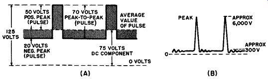
Fig. 1-6. (A) Pulse voltage with a d-c component present. In this particular
example, the peak-to-peak value of the pulse voltage is of the same order as
the d-c voltage. When this pulsating d-c voltage is applied to the input terminals
of a d-c voltmeter, the instrument will indicate 75 volts. In this case, the
a-c voltage component is sufficiently low so that the instrument will not be
damaged. If the value of the d-c component were only 10 volts, for example,
the a-c component would then cross the zero axis, and the wave would not then
be referred to as pulsating d-c, but as a-c with a d-c component. The distinction
is somewhat academic but can lead to confusion if the definitions are not kept
clearly in mind. The pulses present in some tv receiver circuits have peak
values very much greater than the d-c component present, as shown at (B). For
example, the d-c voltage at the plate of the horizontal-output tube may be
of the order of 300 volts, but the pulse voltage which accompanies it may be
of the order of 6,000 volts peak-to-peak.
1-6. Operating an Instrument with a High-Voltage Probe Safety Precautions

TABLE 1-3 HIGH-VOLTAGE (D-C) MULTIPLIER RESISTANCE SELECTION CHART FOR VTVM's
----Compiled from information supplied by Precise Development Corp.
End-Connector Type Code:
• = Amphenol MC-IF (or equivalent)
screw-on type mike (panel) connector.
t = Amphenol MC-1F connector plus Amphenol MC-1P phone jack
•• = Pin plug.
The resistive high-voltage probe is employed by removing the original d-c test lead from the vom or vtvm and substituting the inner conductor of the probe cable for it. The gnd terminal of the vom or vtvm should be connected to the shield of the probe cable and to the chassis or the B-minus line of the equipment under test. Remember that the shielding in a high-voltage probe and its cable must always be grounded as directed above, otherwise the entire test system will be "hot" and the operator may receive a severe and possibly dangerous shock. (When testing the circuits of transformerless tv receivers, an isolation transformer should be connected between the receiver and the a-c power line to prevent the possibility of placing a short across the power line if the meter case and chassis should accidentally become grounded). The range switch of the meter should be set to the proper position (in most cases, this is the one for the highest d-c voltage range of the meter). Multiply all voltage indications obtained on this range by the multiplying factor of the probe.
It is advisable to form the habit of keeping your unoccupied hand in your pocket whenever you are making high-voltage measurements. The other hand should hold the handle end of the probe only, keeping it as far away from the safety flanges as possible. It is also advisable to make the connection to the circuit with the power off, then apply power and read the voltage value.
1-7. Use of High-Voltage D-C Probe as a Low-Pass Filter in the Measurement of D-C Voltage with High-Voltage A-C Pulses Present
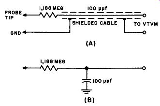
Fig. 1-7. (A) A high-voltage resistive probe with the capacitance of its shielded
cable is seen to have the characteristics of a low-pass filter (B). This property
of the probe is useful in measuring d-c plate voltage values in the presence
of high-voltage short-duration a-c pulses at the plate of the horizontal-output
tube of a tv receiver, without damage to the vom or vtvm.
It is frequently necessary to employ a vom or a vtvm to measure d-c voltages of the order of several hundred volts in the presence of very high voltage short duration pulses of the order of several thousand volts, without damaging the vom or vtvm (see Fig. 1-6). For example, this condition exists at the plate of a horizontal output tube in a tv receiver where the d-c voltage may be only 300 or 400 volts but it is accompanied by sharp, short-duration pulses of approximately 4,000 to 6,000 volts peak-to-peak.
While each high-voltage pulse does not affect the pointer deflection of the d-c voltmeter directly, it may send a large pulse current through its multiplier resistor network. This current can cause serious damage by overheating or burning out the voltage-divider resistors.
However, it is quite practical to measure the d-c voltage at the plate of a horizontal-output tube without damage to the voltmeter if a high-voltage d-c probe is used. In this case, the high-voltage probe is not used primarily to attenuate the measured voltage but to serve together with the input capacitance of the shielded cable and voltmeter, as a filter which keeps large short-duration pulse currents from flowing. However, the d-c voltage will also be attenuated, so a low-voltage meter range should be used. A 100-to-1 resistive high-voltage probe is convenient; the range switch of the voltmeter must then be set to a low-voltage range, such as 3 or 4 volts full scale. When the range switch is set to the 3-volt range, a 100-to-1 high-voltage d-c probe will provide an effective full-scale range of 300 volts de, but more important it provides the required circuit filtering so that the vtvm is not damaged by the high-voltage pulses.
Consider how much the 6,000-volt pulse voltage is attenuated at the meter terminals. Assume that a vtvm having an input resistance of 12 megohms is used.
The 100-to-1 multiplier resistor will have a value of 1,188 megohms. Accordingly, 1/100 of the applied d-c voltage appears at the vtvm input terminals. However, the attenuation factor for the unwanted pulse voltage is very much greater.
Suppose that the total input capacitance of the shielded cable plus the vtvm input capacitance is 100 µµf, see Fig. 1-7A. The equivalent circuit is shown in Fig. 1-7B. At the fundamental frequency (15,750 hz) of the horizontal-output pulses, this capacitance has a reactance of about 0.1 megohm, which causes a pulse attenuation of about 12,000 to 1. In other words, only about ½ volt ac (pulse) appears across the vtvm input terminals.
1-8. Use of 100-to-1 Resistive High-Voltage Probe to Increase the Input Resistance of a VTVM for Measurement of Low Voltages in High-Resistance Circuits
The vertical blocking oscillator in a tv receiver often has a high grid impedance, with a resistance component of 10 megohms, or more. Under such circum- stances, the application of a vtvm to measure the grid bias seriously disturbs the circuit operation, as the circuit resistance is reduced to approximately one-half by application of the instrument.
To avoid this type of trouble, the operator may make use of a 100-to-1 resistive high-voltage probe. The multiplier resistor in such a probe has a value in the order of 1,000 megohms, which is sufficiently high so that it does not disturb the grid circuit of the vertical blocking oscillator. If the vtvm is operated on the 1-volt range, the full-scale indication becomes 100 volts, and a grid bias of -75 volts represents three-quarters full-scale deflection.
1-9. Objections to use of a Resistive High-Voltage Probe with a Scope to Display Waveforms of High A-C Voltages
A resistive high-voltage probe may be used with a vtvm to accurately and safely measure the value of the high second-anode voltage at the tv picture tube, or the high voltage at the plate of the horizontal output tube, or at the plate of the damper tube. Technicians sometimes fall into the error of trying to go a step further by using the same type of probe with an oscilloscope that has pro vision for a-c input only, in an attempt to display and measure the peak-to-peak value of the sweep voltage, the ripple present in the high voltage applied to the picture tube second anode, etc. When this is attempted, practically the full high voltage being applied to the probe input circuit can also he present at its out put circuit and this may cause breakdown of the input blocking capacitor within the oscilloscope (see Fig. 1-5A). The blocking capacitor in the scope is usually rated at only 600 volts.
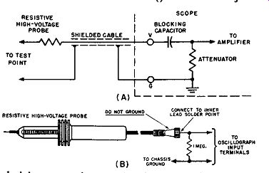
Fig. 1-8. (A) Technicians sometimes make the error of attempting to use a
resistive high-voltage probe with an a-c type oscilloscope to observe the ripple
in the high-voltage supply. This leads to possible breakdown of the blocking
capacitor in the scope input circuit. Use of the alternative circuit arrangement
( B), which is often suggested, is also open to several objections which are
discussed in the accompanying text.
It is sometimes recommended in servicing literature that a check of these voltages can be made with a high-voltage probe and a-c type scope if a 1-meg resistor is connected in shunt with the scope input terminals as shown in Fig. 1-5B. Although scope capacitor puncture is avoided by this method, there are other serious drawbacks to its use. These are: (1) since the actual attenuation factor of the probe when used with the a-c scope is unknown, the peak-to-peak voltage of the ripple cannot be measured; (2) the multiplier resistor in this type of probe is unshielded, so it is quite susceptible to hand-capacitance effects and to variable capacitance effects to surrounding metallic objects. Also, whenever such a probe is used in the vicinity of stray fields, spurious voltages induced in the resistor by them cause spurious displays that interfere with the main display; (3) the d-c probe is uncompensated, and always introduces some degree of distortion into the desired waveform. Because these actions make it impossible to obtain accurate display of the peak-to-peak voltages on the screen, they cannot be measured accurately.
Such a high-voltage d-c probe cannot be used in such tests with a d-c scope, since the high d-c voltage which is present (with respect to the relatively small a-c ripple voltage) deflects the scope beam off screen whenever the vertical gain control is advanced sufficiently to obtain a sizeable pattern.
A resistive type high-voltage probe designed for use with a vtvm should, therefore, be used only with a vtvm. When high a-c voltages are to be investigated with a scope, the technician should employ a suitable high-voltage capacitance-divider a-c type probe (see Section 2). Such probes largely avoid waveform distortion and stray-field pickup, and have a known attenuation factor.