AMAZON multi-meters discounts AMAZON oscilloscope discounts
2-1. Need for an A-C Voltage Divider in the Use of Scopes for High-Voltage Circuit Testing
Troubles in the various high-voltage circuits of tv receivers can usually be located very quickly by means of suitable signal-tracing techniques employing the proper instruments. D-c voltage measurements in the high-voltage circuits present no particular problem, for they can be made with a vom or a vtvm in combination with a suitable resistive high-voltage multiplier probe, as explained in Section 1. However, it is frequently necessary to employ an oscilloscope to measure the peak-to-peak values, or to observe the waveforms, of the high voltage pulses present at several points in these circuits--especially in the 15,750 hz horizontal sweep circuits. Whenever oscilloscopes are employed in high voltage circuits, it should be remembered that they are rated by their manufacturers as to the maximum allowable voltage which may safely be applied to their input terminals, and the majority of these ratings for service-type scopes are of the order of only 600 volts.
Excessive input voltage applied to a scope can do harm in several ways. It may actually puncture the blocking capacitor, and char or burn out attenuator resistors. It may arc through terminal-insulating washers and carbonize terminal strips. Or, it may overload the scope amplifier and distort the displayed wave form without doing actual physical damage to the scope. In fact, although rated at around 600 volts maximum input, many service-type scopes become over loaded and begin to distort the reproduced waveform when much lower voltages are applied to the vertical input terminals.
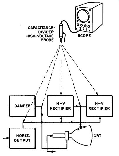
Fig. 2-1. Tv receiver high voltage 15,750 hz horizontal sweep circuit in which
a capacitance-divider type high voltage probe must be used with a scope for
a-c voltage measurement or waveform observation.
It is evident that some of the a-c voltages encountered in a tv receiver chassis are sufficiently high to damage the scope input circuit if applied directly to the vertical input terminals of the scope for either voltage measurement or wave form observation. The sweep voltage at the plate of the horizontal-output tube, which may be as high as 6,000 volts peak-to-peak, which is the key voltage to be checked in most horizontal sweep circuit troubleshooting, is a case m point. The voltages at the plate of the damper tube, at the plate of the high-voltage rectifier tube, and in the high-voltage filter circuits, are similar examples (see Fig. 2-1). To protect a scope against damage when such high a-c voltages must be checked, it is necessary to employ a suitable voltage divider which will make it possible to apply only a fraction of the actual test circuit voltage to the oscilloscope input terminals and still preserve the waveshape that is to be observed.
Furthermore, if actual measurement of the voltage is required, the voltage divider must attenuate the test circuit voltage by a definite known factor so that the peak-to-peak (or other) value can be read from the calibrated scope screen.
One possible method of protecting a scope against damage when such high a-c voltages must be checked was discussed earlier, in Sec. 1-9. It utilizes a conventional resistive type high-voltage (d-c) probe, that is connected in series with the vertical-amplifier d-c input of the oscilloscope (in oscilloscopes which provide such a connection). The multiplier resistor in the probe and the internal resistance of the scope functions as a voltage-dividing network. This combination can be designed to provide a voltage-reduction ratio of 1,000 to 1 if desired, depending upon the internal resistance of the scope and the multiplier resistance used. With this stepdown ratio, a 20,000-volt signal input for example, will provide a 20-volt signal to the scope input. If the scope being used has provision for a-c input only, a d-c path may be provided by shunting a 1-megohm resistor across the input terminals as shown in Fig. 1-5B. The a-c voltage division obtained with this arrangement is not as accurate as the d-c voltage division because the capacitance between the probe body and ground varies with every change of position in which the probe is held. Because the capacitance shunts the multiplier resistance, the divider ratio for a-c is variable. Unfortunately, these variations are particularly noticeable at the 15,750 cycle horizontal-deflection frequency range in which most of the measurements and tests where this arrangement might he used are made. Consequently, this arrangement is unsatisfactory for tests where it is necessary to measure the amplitude of the voltage waveform.
Another objectionable condition is that crosstalk fields in and around the high-voltage section of a tv receiver enter the unshielded portion of the probe and produce undesired currents in the internal series resistor. These currents combine with the desired currents, thereby causing distortion of the observed waveform. Consequently this arrangement is not satisfactory for tests in which it is necessary to carefully check the waveform of the voltage under observation. This arrangement is generally satisfactory only for those high-voltage signal-tracing applications where the only scope indication required is one that shows either the presence or the absence, and the general shape of, the a-c voltage wave.
A resistive type voltage-divider is satisfactory for use in d-c and low-frequency a-c circuits. For higher frequencies, such as the horizontal deflection frequency in a tv receiver, a capacitive form of voltage divider provides much more satisfactory operating characteristics.
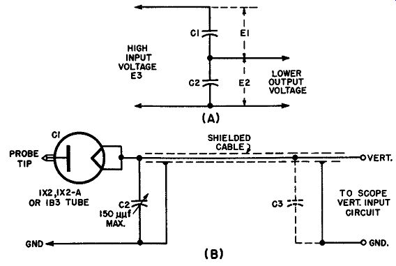
Fig. 2-2. (A) Basic circuit arrangement of a capacitive-type voltage divider.
(B) A practical capacitance-divider type high-voltage probe for attenuating
high test voltages to the lower values that lie within the safe input voltage
rating of the scope.
Trimmer capacitor C2 is adjusted to provide the correct desired voltage-stepdown ratio when the probe and its cable are connected to the input circuit of a given scope.
2-2. The Capacitive Type of Voltage Divider
In the capacitive type of voltage divider, the high voltage is applied to two capacitors connected in series, as illustrated in Fig. 2-2A. A division of the applied voltage takes place, with a portion appearing across each capacitor. Consequently, this arrangement may he used as a voltage divider between high- voltage test circuits and the scope input terminals to reduce the test signal voltages to suitable lower values that can be safely handled by the input circuit of the scope. This enables a scope to be used for a-c high-voltage testing which would otherwise damage the input circuit of the instrument. The voltage divider is usually made up in convenient probe form, with a shielded cable for connection to the scope input terminals.
The voltages which appear across the individual capacitors are in inverse ratio to the capacitances (and their reactances). Thus, the following relationship exists in the circuit of Fig. 2-2:
also, Er gives, Er C2
= E2 Cr
E3 - E2.
Substituting the value for Er in the foregoing equation E3 - E2 C2, E3 C2
------ = -- from which -- - 1 E2 Cr E2 Cr
Since E3 is the required voltage-stepdown ratio, r,
E2 we have C2, r - r = -- or C2 = Cr (r-r)
Cr
This last equation enables the value of C2 to be easily calculated when the voltage-stepdown ratio and the Cr value that will be used have been decided upon.
For large voltage stepdown, capacitance Cr is much less than capacitance C2. Any proportion of voltage division may be affected by proper choice of the two capacitances to provide the desired voltage ratio in accordance with the above equations.
2-3. Practical Capacitance-Divider High-Voltage Probe Design
The essential elements of a practical high-voltage capacitance-divider probe are illustrated in Fig. 2-2B. The input impedance (which varies with the frequency) is made as high as possible to minimize loading of the high-voltage receiver circuits under test, so that the measured peak-to-peak voltage values will be correct. Since the probe is to be used exclusively for high-voltage circuit testing, high-voltage insulation must be provided in its construction. Commercial probes are shielded to minimize hand-capacitance effects and stray-field pickup that would alter the scope trace.
In order to safely withstand the highest voltages encountered in tv receiver test work, the first capacitor, Cr, employed in the network usually consists of a high-voltage rectifier tube, such as a 1 x 2, 1 x 2-A, or a IB3, connected not as a rectifier but as an inexpensive small high-voltage capacitor. The plate-to-filament capacitance of these tubes ranges between approximately 0.9 to 1.5 uuf, and their breakdown voltage is upwards of 15,000 volts. The tube should not be gassy, or it will not withstand the high potentials encountered.
Capacitor C2, which is mounted within the probe head, is of the variable trimmer type so that the ratio C2/Cr can be adjusted to the correct value to pro-duce the desired voltage-attenuation ratio (usually 100-to-1) at any time. In a 100-to-1 ratio probe, the trimmer capacitor need withstand only about 1/100 of the voltage applied to the probe tip. Since the highest voltage encountered in the applications where such probes are used in tv receiver work is less than 20,000 volts, the trimmer capacitor need not have a voltage rating higher than about 200 volts.
In Fig. 2-2B, C1 represents the combined capacitance of the shielded cable plus the input capacitance of the scope. Since C1 parallels C2, the voltage division ratio and probe calibration will be affected by any change in either the cable capacitance or the scope input-circuit capacitance. Consequently, since the probe trimmer C2 is adjusted to provide the correct voltage-stepdown ratio with a given shielded cable and scope capacitance, the calibrating capacitor C2 must be readjusted whenever the probe is used with a different cable or scope.
Service technicians who do not need to use a capacitance-divider type high voltage probe sufficiently often to warrant the expense of purchasing the ready made variety may construct the simple home-made 100-to-1 probe, illustrated in Fig. 2-3. This consists of two lengths of RG-59/U coaxial cable. All of the outer braid is removed from the shorter length of coax, and approximately 3½ inches of outer braid is removed from the longer length. The two pieces of coax are placed so that they overlap 3 inches, and are taped together. Plastic electrical tape should be used for this purpose. A 100-µµf, 500-volt capacitor is connected between the inner and outer conductors of the long piece of coax. If a variable trimmer type capacitor is used, it may be adjusted to obtain a stepdown ratio of exactly 100-to-1, so that the calibration factor of the scope will be changed by a decimal value (add two zeros) when the probe is employed. Also, the step down ratio may be "touched up" whenever it becomes necessary.
2-4. Choice of the Voltage-Stepdown Ratio, and Maximum Voltage Rating
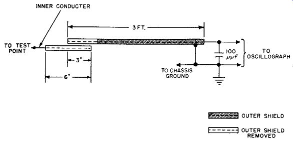
Fig. 2-3. Simple shop-constructed capacitance-divider type high-voltage probe
made of coaxial cable. The voltage stepdown ratio is approximately 100-to-1.
Courtesy: DuMont Service News.
Since it is preferable for convenience in estimating the signal voltage from the height of the trace produced on the scope screen, the voltage-divider probe is usually designed to provide decimal attenuation; i.e., the stepdown ratio is usually made either 10-to-1, or 100-to-1, the latter being the most commonly used since the greater attenuation is more often required when high-voltage circuits are to be tested. If a 1,000-volt wave is applied to the input terminals of a 100-to-1 voltage divider, only 10 volts will be applied to the input terminals of the scope. If the scope screen has been calibrated for peak-to-peak sensitivity of 1 volt per square, the 1,000-volt wave will produce 10 squares of deflection on the screen. By using such a decimal voltage-divider, it is not necessary for the opera tor to recalibrate the scope every time the attenuator is employed with it. He merely adds one zero or two zeros, as the case may be, to the original scope calibrating factor.
When circuits in which high voltages of lower levels exist are being checked (as for example when checking the waveform across the horizontal-deflection coils of a tv receiver), it is often more desirable to use a divider probe having a ratio of only 10-to-1 so that sufficient voltage is applied to the scope input terminals to produce adequate deflection for accurate waveform study or peak-to-peak voltage measurement, without overloading the scope amplifier.
The design of the probe must be such that it is able to safely withstand the maximum circuit voltage to which it will be subjected at any time. A rating of at least 30kv is required for picture-tube second anode voltage checks in mono chrome and color tv receivers.
2-5. Adjusting the Trimmer Capacitor for Correct Voltage-Stepdown Ratio
If the high-voltage capacitance-divider probe is used when the peak-to-peak voltage values of waveforms are to be measured by the scope, the probe should be adjusted accurately for 100-to-1 (or 10-to-1) stepdown voltage. A simple method of doing this, for a scope that contains a 100-to-1 input attenuator is given below.
Most tv service scopes are provided with a decimal step attenuator. To check the calibration of a 100-to-1 probe, first apply the scope input terminals alone across a low-impedance circuit, such as the cathode circuit of a tv receiver damper tube, using direct leads to the scope. Set the scope step attenuator to the lowest-sensitivity (Xz) position, and adjust the vernier attenuator for any convenient number of squares of deflection on the screen. Then connect the probe between this same signal point and the scope input and advance the step attenuator to the Xzoo position (100 times as sensitive). If the attenuation factor of the probe is correct, the waveform will then occupy the same number of squares on the scope screen as before. If it does not occupy the same number of squares, the probe trimmer may be suitably adjusted by means of an insulated screw driver until it does. It is then in correct adjustment to produce 100-to-1 voltage attenuation when it is used with that particular shielded cable and that particular scope input circuit.
Some service scopes are in use which do not have a compensated input system. It should be observed that the input capacitance of such a scope will vary as the scope attenuator is varied, and hence the calibration factor of the probe will also be changed somewhat. Further, it is very likely that waveform distortion will be encountered at the lower settings of such an attenuator, due to frequency discrimination and phase shift in the attenuator itself.
2-6. Test Circuit Loading Effects of Capacitance-Divider Type High-Voltage Probes
Because the input capacitance of a 100-to-1 high-voltage capacitance-divider probe is usually less than 2 µµf, as compared with an input capacitance of approximately 8 µµf for a typical 10-to-1 high-voltage capacitance-divider probe, the 100-to-1 probe has a much higher input impedance than the latter, hence imposes much less loading on the circuit to which it is applied.
The reduced likelihood of circuit loading imposed by a high-voltage 100-to-1 capacitance-divider probe is an advantage in many tests. However, this probe cannot be used in low-level circuits because it may be impossible to obtain usable vertical deflection on the scope when the voltage is attenuated to only 1/100 of its original value by the probe.
Most typical service scopes have a vertical-deflection sensitivity of approximately 0.02 volt rms per inch at full gain, corresponding to a sensitivity of 0.057 volt peak-to-peak per inch. Under these conditions, the 100-to-1 probe will provide 1 inch of deflection for an input signal of 5.7 volts peak-to-peak. If the signal voltage is less than this, the 10-to-1 probe will probably have to be used in order to obtain usable deflection on the scope.
The input impedance of the capacitance-divider type of high-voltage probe is relatively high, but becomes less as the frequency increases. The variation of the input impedance of the type of probe shown in Fig. 2-2B in the horizontal sweep frequency range is shown in Fig. 2-4. The value of the input impedance is determined by the plate-filament capacitance of the tube used in the voltage divider.
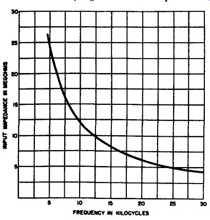
Fig. 2-4. The input impedance of a typical capacitance divider type high-voltage
probe decreases as the frequency increases.
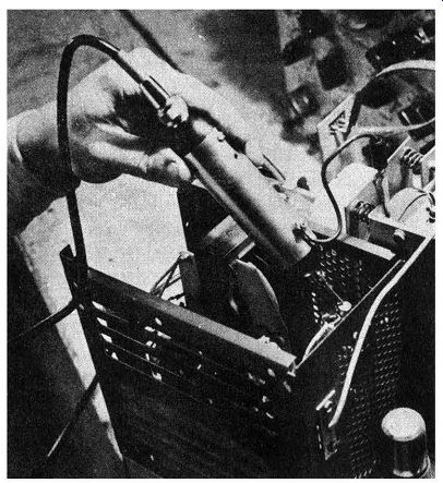
Fig. 2-5. Close-up of a 100 to-1 capacitance-divider type high-voltage probe
being applied to the plate terminal of the horizontal-output tube of a tv receiver
in order to check the 6,000-volt peak-to-peak voltage and examine its wave
form at that point, without impairing the waveshape or incurring danger to
the input circuit of the scope. This particular probe is useful to 10,000 p-p
volts. Observe the grounding lead from the probe shield clipped to the receiver
chassis. Courtesy: Scala Radio Co.
At lower frequencies, such as 60 hz, the input impedance of the probe becomes extremely high. However, the probe cannot be used in circuits of such low frequency such as a vertical sweep circuit, because it is uncompensated.
Therefore the very small series capacitance of the tube used in it, in conjunction with the input resistance of the scope, distorts the waveform of the voltage under test. Spikes (high-frequency components) in the waveform are passed satisfactorily, but the low-frequency sawtooth component is distorted.
2-7. Capacitance-Divider Type High-Voltage Probe Applications and Practical Operating Hints (1) Troubleshooting Horizontal-Sweep Circuits.
The capacitance-divider type high-voltage probe is an uncompensated type of probe, and although it does have some other uses, it is intended primarily for use in troubleshooting the horizontal sweep circuits of tv receivers, where the frequency is 15,750 hz, and the capacitive component of the scope input impedance dominates the attenuation factor of the arrangement. It can be applied, for example, at the plate of the horizontal-output tube, as shown in Fig. 2-1 and Fig. 2-5, or at the plate of the damper tube, to examine the operating waveforms and to measure their peak to-peak voltages, without impairing the waveshape or incurring danger of dam age to the scope. The shape of the wave helps the technician identify certain defects in the flyback transformer, and the p-p voltage shows the condition of the drive circuit.
When used in such applications, the scope should first be calibrated for a known sensitivity in peak-to-peak volts of deflection per square on the ruled graph screen. The probe is then connected to the scope, and the calibration factor is multiplied by 100. For example, if the scope has been calibrated for a sensitivity of 10 peak-to-peak volts per square, the 100-to-1 high-voltage probe converts this calibrating factor to 1,000 peak-to-peak volts per square, and a 6,000 peak-to-peak volt waveform will occupy six squares on the scope screen.
The operator should note that the peak-to-peak voltages of such waveforms are usually specified in the service notes for the tv receiver with a tolerance of about 20 percent, which means that the receiver operation is to be judged faulty if a wave that is normally 6,000 p-p volts should measure more than 7,200 p-p volts, or less than 4,800 p-p volts. It must also be observed in this regard that variations in power-line voltage are reflected through the receiver circuits as variations in measured peak-to-peak voltage values. Receiver manufacturers specify waveform voltages upon the basis of a design-center a-c line voltage of 117 rms volts.
(2) Troubleshooting 60-Cycle Vertical-Sweep Circuits. Capacitance-divider type high-voltage probes should not be used in the 60-cycle vertical-sweep circuits of a tv receiver, because at 60 cycles the capacitance of the probe is working into an effectively constant resistance. The reactance of the probe input capacitance is not constant, but decreases with increase of frequency (see Fig. 2-4). In consequence, each harmonic component of the waveform undergoes a different attenuation, so waveform distortion results due to the resulting frequency discrimination and phase shift. Because of such distortion, use of this probe in circuits of such low frequency must be restricted to those applications where the technician needs to determine the presence or absence of a waveform without concern about its shape (see also No. 4 below).
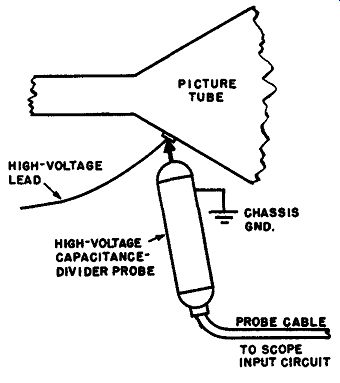
Fig. 2-6. High-voltage ripple and 60-cycle regulation buzz can be displayed
on the scope screen with the use of a capacitance-divider type high-voltage
probe applied to the crt second-anode terminal. (See also Fig. 2-7 and Fig.
2-9.)
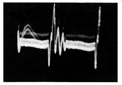
Fig. 2-7. Typical ripple voltage on the output voltage of the high-voltage
supply at the second-anode of the picture tube.
(S) Checking for Ripple Voltage in the High-Voltage Supply. The alert technician may be interested in additional applications of the capacitance-divider high-voltage probe, such as the one illustrated in Fig. 2-6. This test displays the ripple voltage on the output of the high-voltage supply, as shown in Fig. 2-7.
When the ripple is excessive, the beam current in the picture tube is modulated by the ripple, and alternate light and dark gray vertical bars appear on the left hand side of the raster. The scope is swept at 15,750 cycles per second (or a sub-multiple) to display the ripple voltage. A probe having a voltage rating of at least 20,000 volts is required for making this test in black-and-white receivers (see Table 1-1 in Section 1). The color tube in color tv receivers is operated at higher voltages, and a probe with a voltage rating of at least 110,000 volts may be required for such receivers.
Occasionally the technician makes the error of attempting to use a resistive type high-voltage probe with a scope to observe the ripple on the high-voltage supply. This leads to trouble, because after a short time the blocking capacitor in the scope input circuit charges up to puncture voltage, and ruptures. Only a capacitance-divider type high-voltage probe should be used for such tests.
(4) Checking for 60-Cycle Buzz Pulse. When the scope is swept at 60 hz, the same test may be used to check for the presence of 60-cycle buzz pulse in the output from the high-voltage power supply. The buzz pulse is developed by modulation of the beam current in the picture tube by the vertical sync pulse at the grid of the picture tube. The appearance of such a buzz pulse is shown in Fig. 2-8.
In case the d-c voltage at the second anode of the picture tube exceeds the voltage rating of the probe, a series blocking capacitor C should be used, as shown in Fig. 2-9. In this case, the attenuation factor of the probe is altered. It must be remembered that the operating characteristics of a high-voltage capacitance-divider probe are such that ripple voltage is displayed on the scope with its actual waveshape, whereas a buzz pulse of lower frequency is displayed distorted to a greater or lesser extent. However, the distortion encountered when displaying such 60-cycle waveforms is of little concern to the technician, because he is usually interested only in determining whether or not the buzz pulse is present.
In case it should be desired to obtain the true shape of such 60-cycle pulses, it becomes necessary to use a high-voltage type of compensated R-C low-capacitance probe. Such probes are somewhat bulky and their applications are some what limited; hence they are not often used in service work.
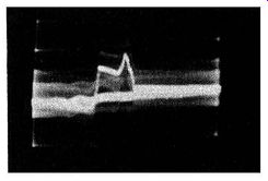
Fig. 2-8. 60-cycle buzz pulse at the second anode of the picture tube, displayed
by a capacitance-divider high-voltage probe and scope (sine wave sweep). The
low-frequency characteristics of the probe are such as to distort the pulse
waveshape, but since the technician needs chiefly to determine only the presence
or absence of the pulse, the distortion is not important in this application.
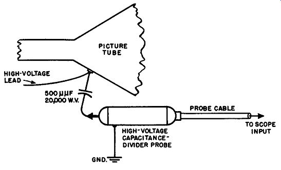
Fig. 2-9. When testing at the second anode of the picture tube for ripple,
or for tunable buzz pulses, it is good practice to place a d-c blocking capacitor,
C, in series with the voltage-divider probe, as shown here, for protection
in the event that the d-c voltage at this point exceeds the voltage rating
of the probe.
Another method which is used to obtain good waveform with 60-cycle pulses is to increase the capacitance of both of the capacitors in the probe, in order to minimize the effect of the input resistance of the scope. However, the increased input capacitance causes such a probe to load the circuit under test more heavily, and the probe is accordingly less useful for tests in other circuits where the operating frequency may be higher.
(5) Video Amplifier Tests. When tracing low-frequency square waves through a video amplifier, a capacitance-divider type probe should not be used because excessive wave distortion will result. The only satisfactory method of investigating the operation of a video amplifier at low frequencies is by means of a properly compensated R-C low-capacitance probe. Of course, the scope used must have adequate low-frequency response for this use.