AMAZON multi-meters discounts AMAZON oscilloscope discounts
3-1. Probe and/or Test Leads Become Part of the Test Circuit
The internal input circuit of commonly used test instruments, such as vom's, vtvm's, and scopes, are customarily brought out to two or more externally mounted terminals located in a convenient position on the case. Consequently, in order to apply the instrument to selected points in a circuit under test, it is necessary to extend the instrument circuit from these input terminals to the circuit under test by means of a pair of suitable test leads, or by a cable. Various ways of doing this are illustrated in Fig. 3-1. If the particular test conditions make it necessary to use a probe of some kind with the instrument, the probe is attached to the test end of the cable so that its tip may be applied directly to the point of test.
Thus, the function of the pair of test leads (or the test cable) is basically to serve as the electrical link between the test instrument and the circuit under test. In doing so, it becomes an integral part of the instrument input-circuit system. If a probe is employed, its electrical components and internal wiring also become part of this circuit. This is a vital point to be recognized and kept constantly in mind because, as will presently be explained, the high-frequency operating characteristics of the test leads or cable may introduce undesirable effects on the operation of the circuit under test; or the cable and/or probe may allow spurious voltages to be induced in them by extraneous fields, and these spurious voltages enter the input circuit to the instrument. The instrument indication may be adversely affected in either case, so a true indication of the conditions existing at the test points will not be obtained, and misleading conclusions will result.
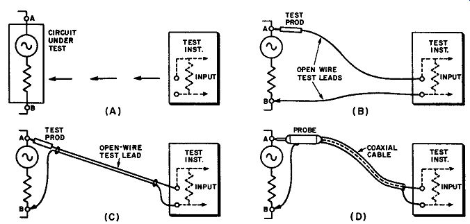
Fig. 3-1. (A) The input circuit of any test instrument must be extended from
the instrument input terminals to the test points in the circuit under test.
Direct test leads, or a probe and cable, may be employed to accomplish this.
(B) Direct test leads employing an open-wire line consisting of two independent
separated wires.
(C) Direct test leads employing open-wire line consisting of a 2-wire parallel-cord arrangement. (D) If a probe of some kind must be used with the instrument, it is inserted in this extension circuit (usually at the test-point end). In either case, the probe and / or test leads, or cable, become an integral part of the test instrument input system.
3-2. Inherent Series Inductance, Shunt Capacitance, and Resonance Effects in Test Leads
Two arrangements of an open-wire line used for the test leads of an instrument are illustrated in Fig. 3-1. Two independent separated wires are shown in Fig. 3-1B; a 2-wire parallel-cord arrangement is illustrated in Fig. 3-1C. There is more than meets the eye here because, from an electrical viewpoint, an open-wire transmission line is far more than just two wires. The current that flows through each wire produces a magnetic field around it, and simultaneously, the potential difference existing between the wires establishes an electrostatic field at right angles to this. These fields are illustrated in Fig. 3-2A. As a result, each elemental (or small) length of wire in the line has inductance, L, as shown in Fig. 3-2B; each elemental (or small) length of line has capacitance, C, between the two wires, and also between each wire and any nearby conductor such as a metal chassis, etc. Also, each elemental length has series resistance, R, and shunt leakage. G, (which can be kept comparatively small in practice, even at high frequencies, by the proper use of modern low-loss insulating materials such as polyethylene). In the separate-wire arrangement in Fig. 3-1B, the distributed capacitance between the wires themselves, and between the wires and other nearby conductors, varies with each shift in position of leads with respect to each other or to the other objects, since this changes the distance between them.
For convenience, these distributed constants may be considered as being lumped at one point along the line as shown in Fig. 3-2C. To them are added the effective L1, R1 and C1 of the input circuit of the instrument itself. The sum total of these are presented to the circuit under test. The total L of this input circuit becomes very important at high frequencies where even a short length of lead, having small inductance, develops appreciable inductive reactance that decreases the signal energy transfer through it. The total distributed or "stray" circuit capacitance (which includes that caused by the proximity of the wires to a metal chassis, to the human body, etc.) also becomes very important, since it results in considerable shunting at the higher frequencies because the reactance of this capacitance decreases as the frequency increases. Also, because of this inductance and capacitance, the input circuit can operate in many circumstances as a resonant stub or circuit.
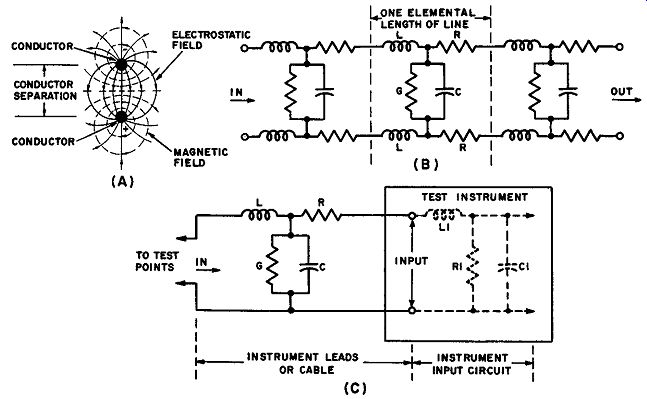
Fig. 3-2. (A) View of the instantaneous magnetic and electrostatic fields
about each wire at one point along an open-wire transmission line. (B) As a
result of the existence of these fields each elemental length of the line contains
series inductance and resistance, and shunt capacitance and leakage. The distributed
constants in an open wire line are shown here. (C) Equivalent circuit, assuming
lumped constants.
These circumstances can often lead to serious consequences when a vtvm or a scope is applied to certain types of circuits under test. An example of this is illustrated in Fig. 3-3 in which a meter is being employed with open-wire test leads to check the plate voltage in a tv i-f amplifier stage. Under these conditions, the test leads act as an open stub whose detuning influence may cause the stage to break into violent oscillation. This causes the value of the plate voltage to change, resulting in a misleading meter indication and consequent incorrect conclusions regarding the condition of the stage.
3-3. Action of Stray Fields Upon Probes and Open-Wire Test Leads
The use of unshielded open-wire test leads and probes may be responsible for other obscure effects which introduce inaccuracies in measurements made in high-frequency circuits. For example, a test lead, or the internal wiring or components of an unshielded probe, may often act as an antenna in picking up signal energy from one circuit and re-radiating it to another circuit in the device being tested. In this way, normally shielded and isolated sections of an electronic device may become cross-coupled to each other by the application of the test instrument-sometimes to such an extent that regeneration or oscillation occurs.
Another objectionable condition is often encountered when open-wire test leads are used with a vtvm or an oscilloscope. The open-wire leads have spurious voltages induced in them by strong stray magnetic and electrostatic fields which may exist about the equipment under test, or by the power-frequency fields surrounding the wiring system of the test bench and nearby wall. For example, strong stray fields commonly arise from the horizontal and the vertical deflection circuits of tv receivers under test. Stray fields from the vertical sweep system are especially bothersome since the vertical deflection circuits carry Power-line frequency (60 cycle) currents. The 15.75- khz fields from horizontal-deflection circuits are also troublesome. The situation is illustrated in Fig. 3-4. When the circuit under test has a high impedance, the spurious interference voltages induced in open-wire test leads used with a scope are likely to result in a corresponding visible interfering pattern on the scope screen. This seriously interferes with the pattern it is desired to check, measure, or study.
Some probes used in tv service work are either unshielded, or only partially shielded, in construction. Such probes often cause incorrect instrument indications when they are used in the vicinity of flyback circuits, etc., in a tv receiver chassis, because the strong stray fields present around such circuits induce spurious voltages in the unshielded components and internal wiring of the probe and these may be sufficiently strong enough to affect the vtvm or scope indication. A simple method for testing a probe to determine whether its shielding is adequate to prevent this is illustrated later in Fig. 7-20.
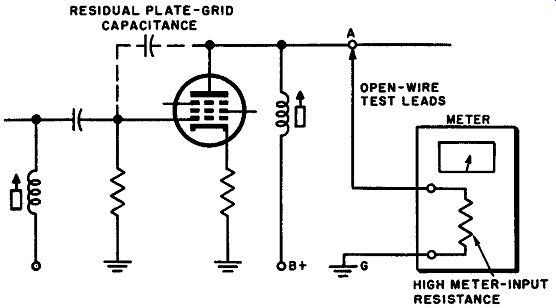
Fig. 3-3. The pair of open-wire test leads work into the high input resistance
of the vtvm. Accordingly, the tv i-f amplifier circuit under test "sees" the
open-wire test lead as a tuned open stub; this stub has a resonant frequency
which changes with each shift in the position of the two wires comprising the
test leads, or of the operator. The amplifier plate circuit may become detuned
by the stub, and if the detuning is such as to make the plate circuit resonate
in the vicinity of the grid circuit frequency, and if there is sufficient tuned-plate
tuned-grid feedback present, the stage "takes off" and oscillates
violently. As a result of the oscillation, the grid of the tube draws current,
which develops a large negative bias on the grid. The negative bias on the
grid changes the amplifier operation from Class A to Class C, and changes the
average plate current through the tube. This change in average plate current
results in a different value of plate resistance, which in turn causes the
distribution of d-c voltage drops in the circuit to change. Under these conditions,
the technician measures an incorrect value of the plate voltage, and draws
false conclusions regarding the conditions of the stage.
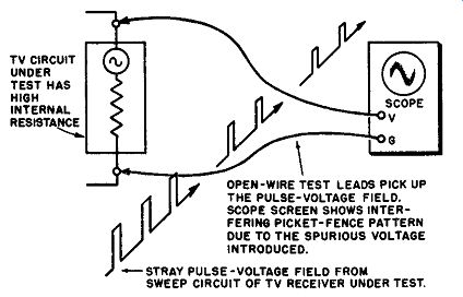
Fig. 3-4. When open-wire test leads are used with a scope, spurious voltages
may be induced in the exposed leads, or in an unshielded probe, by strong stray
fields present about the equipment under test. If the circuit under test has
a high impedance, a corresponding visible interference pattern is likely to
appear on the scope screen.
3-4. Minimizing the Effects of Strong Fields by Means of Shielding
Effective reduction or elimination of spurious-voltage induction by strong fields can be accomplished by employing a suitable shielded construction for those probes which are susceptible to this trouble, and the use of suitable shielded cable (such as flexible coaxial cable), for the test leads between the probe and the instrument, as shown in Fig. 3-ID. The type of coaxial cable commonly employed is illustrated in Fig. 3-5A. The inner stranded-wire conductor is used for the "hot" test prod or probe connection, as shown in Fig. 3-JC. The surrounding one or two layers of copper braiding, which is concentric or "co axial" with the inner conductor, serves as the other conductor of the line and also acts as an electrostatic shield to prevent stray outside fields from inducing spurious voltages in the cable. The instantaneous magnetic and electrostatic fields that exist at a point along a coaxial cable due to the current flowing through it arc illustrated in Fig. 3-5H. Observe that the coaxial construction con fines them entirely within the cable, so there is no external radiation of any of the radio-frequency energy from within the cable.
The wire, W, which serves to connect the outer conductor to the circuit under test should be short. Its contact with the circuit under test should be made as close as possible to the point where the test prod or test probe makes contact with that circuit, because this wire, as well as the corresponding one at the instrument-end of the test cable, is unshielded and so could act as a radiator or could have spurious voltages induced in it by stray fields. If the test cable is viewed as an extension of the measuring-instrument circuit, the logic of effectively shielding the test cable right up to the actual points of contact with the circuit under test, and also up to the instrument input terminals, becomes obvious. This wire also has inductance and capacitance, which can be minimized by keeping it as short as possible. In addition, the use of a fitting that maintains the shielding at the input terminals of the instrument is highly desirable.
3-5. Increased Capacitive Effect in Coaxial Shielded Cable
The use of a shielded input cable represents an important advance over open test leads, because the stray fields about the test bench and equipment under test are rejected hy the shield construction. However, the use of a coaxial test cable is not a cure-all for the troubles encountered in sampling the voltage of a circuit under test for application to the indicating instrument, and it introduces some special problems of its own.
The one important disadvantage to its use is the fact that due to the close proximity of the two conductors in the cable, to their increased effective surface area, and to the higher dielectric constant of the insulating material between them as compared with that of air, the distributed capacitance of a coaxial cable is considerably greater than that of a pair of open-wire test leads of the same length. Consequently, the undesirable effects of distributed capacitance in the test lead are intensified when shielded cable is used. However, the capacitance of the shielded cable is fixed and remains unchanged irrespective of the position or movement of the cable while tests are being made. This is a definite advantage over the variable-capacitance effects encountered during manipulation of the open-wire test leads shown in Fig. 3-1B, and to some extent for those shown in part C of the same figure.
The distributed capacitance of a coaxial cable is a function of the material used for the insulation, and a function of the cable dimensions. (Note: Typical values arc 20 to 30 µµF per foot of cable length.) Obviously the only way to re duce the capacitance by a change in cable dimensions is to increase the ratio of the diameter of the outer conductor (shield) to that of the inner conductor. But beyond a certain point, this results in a cable that is too bulky, weighty, and inflexible and uses a prohibitive amount of comparatively expensive dielectric (which also has r-f losses).
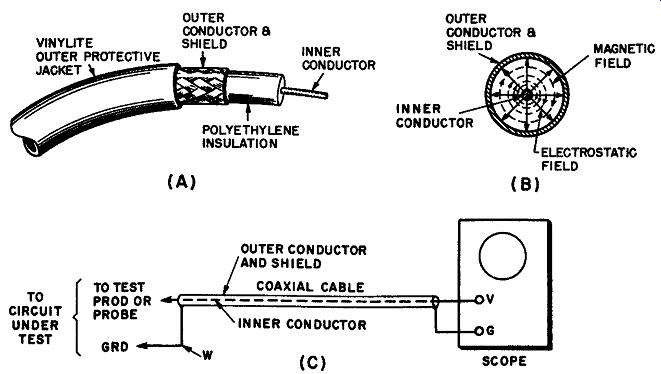
Fig. 3-5. (A) Type of r-f flexible coaxial cable widely employed for test
leads. ( B) The instantaneous magnetic and electrostatic fields that exist
at one point along a coaxial cable due to the current flowing through it at that
instant. (C) Method of connecting a coaxial cable to serve as the test leads
between a test instrument and a test prod or probe.
3-6. Shielded Test Cable may not always appear Capacitive to the Circuit under Test
It is sometimes assumed that because a shielded input cable to a test instrument usually appears capacitive to the circuit under test, that such must always be the case. The shielded input cable will cease to appear capacitive, and will eventually start to appear inductive as the frequency of the test signal increases.
The point at which it begins to act like a coil instead of a capacitor depends upon the length of the cable with respect to the wavelength of the signal under test.
The instrument almost always places a load at the output end of the cable which is higher than the characteristic impedance of the cable (typically 50 to 75 ohms). Under this circumstance, the input terminals of the cable will at first appear as a capacitor at lower frequencies, becoming inductive at higher frequencies. At lengths which are an odd number of quarter wavelengths at the operating frequency, the cable becomes series-resonant; at lengths which are an even number of quarter wavelengths, the cable becomes parallel-resonant. On the other hand, in cases where the instrument places a load at the output end of the cable which is lower than the characteristic impedance of the cable, the input terminals of the cable will at first appear inductive at lower frequencies, becoming capacitive at higher frequencies. At lengths which are an odd number of quarter wavelengths at the operating frequency, the cable becomes parallel resonant; at lengths which are an even number of quarter wavelengths, the cable becomes series-resonant.
As the frequency of the test signal is progressively raised through multiples of the resonant frequency of the shielded cable, the input reactance changes from capacitive to inductive and goes through various resonances. The first resonance occurs when the cable length is one-quarter wavelength at the operating frequency. For a 4-foot cable, this occurs at about 40 mhz, and for a 3-foot cable at about 55 mhz.
3-7. Loading Effects Imposed on the Tested Circuit by Test Cable Plus Instrument
Circuit loading caused by test instruments is a problem which the electronics technician must always keep in mind. Several specialized aspects of this subject, as encountered in the two types of probes discussed in Sections 1 and 2, are explained in Sec. 1-3 and Sec. 2-6. Other reference has frequently been made to "test circuit loading" and its effects on the p-p value and the waveform of the voltage under test. Additional important aspects of this subject must now be considered.
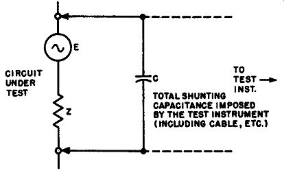
Fig. 3-6. Any typical circuit under test can be represented accurately by
a voltage source E and impedance Z. The test instrument and cable applied to
it shunt it with capacitance C, which loads it capacitively.
Circuit loading may be classified as resistive loading or capacitive loading.
Resonance effects, produced by the application of the testing circuit, may also be considered in conjunction with circuit loading.
(1) Resistive Loading Effect. Because the input circuit of a vom, a vtvm, or a scope (d-c input) has a definite resistance value, its connection to a circuit under test places a resistive load on that circuit. However, the actual degree of the effect of this load upon the circuit operation may vary from negligible resistive shunting to a detrimental reduction of the voltage under test. The latter is more frequently the case if the circuit under test is a low-voltage high impedance circuit (such as a grid-bias or ave circuit, etc.). Resistive loading can be minimized by the use of modern high-resistance type measuring instruments, and in some applications, by the method explained in Sec. 1-8.
(2) Capacitive Loading Effect. Where high-frequency circuits are concerned, the effects of the application of the over-all input capacitance of the vtvm or scope across the circuit under test is usually of far greater importance as regards possible disturbance of the circuit operation than is the resistive loading imposed. For a setup consisting of the measuring instrument, the test cable, and test prods or a direct-type probe, the total or over-all input capacitance is equal to the sum of the paralleled capacitances of these individual devices. For example, if the capacitance of a direct-type probe together with its associated coaxial cable is 60 uF, and the input capacitance (vertical input circuit) of a scope with which it is to be used is 30 uF, the over-all input capacitance being applied to the circuit under test is 90 uF.
Unfortunately, the capacitive loading which a test instrument (inducing its cable) imposes on a circuit under test is not always considered from the proper, correct or complete viewpoint. The value of the shunting capacitance, C, itself does not determine completely the degree of the loading; consequently, it is not sufficient to merely specify the over-all input capacitance which the measuring circuit applies to the circuit under test. This capacitance value means nothing unless it is considered with respect to the internal impedance of the circuit under test, as shown in Fig. 3-6. Any tube, transformer, or coupling capacitor, can be properly represented as a source of voltage, E, in series with an impedance, Z, which has a value equal to the internal impedance of the circuit under test. It is the value of the reactance of C as com/Jared with the value of Z which determines whether or not the loading is appreciable. If Z is small, compared with the reactance of C, C does not load the circuit appreciably; if Z is large compared with it, C may appreciably alter the operation of the circuit and the voltage and waveform appearing at the test points. In some cases, it may kill the circuit action entirely.
The question to be asked, then, is this: Is the reactance of the over-all capacitance, C of the measuring circuit large, or is it small, with respect to the internal impedance of the circuit under test? And it must be remembered that the reactance of C is not a constant quantity, but decreases as the circuit frequency increases.
The consideration is often expressed in another manner: A given value of shunting capacitance loads a high-impedance circuit more heavily than it loads a low-impedance circuit. For example, the primary of a horizontal-deflection trans former is a fairly low-impedance circuit, but the primary of a ratio-detector transformer is a high-impedance circuit. Thus, although we can satisfactorily use a direct simple coaxial input cable when measuring the peak-to-peak a-c voltages of a horizontal-output transformer, we shall be disappointed if we try to use the…
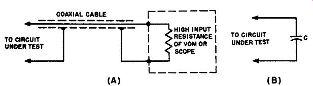
Fig. 3-7. (A) The shielded coaxial cable works into the high input resistance
of the vtvm or scope. For all practical purposes, the coaxial cable can be
properly regarded as an open stub. Therefore, the cable has a resonant frequency,
at which its input terminals "look like" a low resistance (usually
75 ohms). At frequencies below resonance, the cable "looks like" a
combination of capacitance and resistance. (B) At low frequencies, the cable "looks
like" a capacitor C. The value of C is considerably greater than for a
pair of open test leads of the same length, and this is the price that is paid
for immunity to stray fields. Naturally, this capacitance can cause the same
types of detuning effects in resonant circuits or in low capacitance circuits
to which the cable may be connected, as has already been noted for open-wire
test leads ( see Sec. 3-2 and Fig. 3-3). The application of this overall capacitance
to the test circuit is not harmful in some tests, but in others it may alter
the operation of the test circuit sufficiently so that the voltage wave indicate
is not the true one as regards either peak value or waveform.
… cable alone when measuring the peak-to-peak a-c voltages of a ratio-detector transformer because it will severely load the latter and cause the waveform and p-p value of the voltage to change.
Because the shunting effect of the over-all input capacitance increases with an increase in frequency, appreciable attenuation of the higher frequency components in the test voltage may result, thereby altering its waveform if it happens to be a complex wave or pulse that has considerable high-frequency content.
(3) Resonance Effects. Another important effect which the over-all input capacitance of the vtvm or scope may have on the circuit under test is illustrated in fig. 3-7. As mentioned previously, the input cables used with test instruments become series-resonant at some frequencies, and anti-resonant (parallel-resonant) at others. This causes abnormal increase or decrease of output voltage to the instrument to occur if an input voltage having an r-f component of these frequencies is fed to the cable. In severe cases, the series-resonance action may in crease the output to several times the voltage of the input, while at others, the anti-resonance action may reduce the output to practically zero. Such erratic frequency response characteristics can be very troublesome when measurements are being made, if the cable resonances occur at the frequencies of the input test voltage to the cable. Consequently, as we shall learn presently, steps are usually taken to filter out all r-f variations in the output voltage of rectifying and de modulator probes so that resonance effects in the cables used with them are minimized.
The Ferranti effect causes a probe used with an input cable to a test instrument to appear to have increased sensitivity at some frequencies and decreased sensitivity at other frequencies as a result of standing waves which occur on the cable. Standing waves always occur on improperly terminated cables or lines when the operating frequency corresponds to a wavelength for which the cable may be regarded as "long." A cable is electrically long when its input impedance differs appreciably from its characteristic impedance. This situation produces some harmful effects when the cable happens to be an odd or even multiple of one-quarter of the operating wavelength (quarter-wave stub). An eighth-wave stub may also be troublesome, although it is less pronounced in its effects than a quarter-wave section.
3-8. Why Loading Effects of the Measuring Circuit Must Often be Minimized
It is obvious that the actual degree of the effect of the over-all input capacitance of the vtvm or scope may vary from negligible shunting in some circuits under test, to complete upset of the normal operation in others, the latter resulting in susceptibility to the very approach of a test prod to the circuit. To summarize:
(1) Use of unshielded input test leads, under some testing conditions, may result in appreciable pickup of spurious pulse voltages and hum voltages that may alter the a-c readings obtained on a vtvm, or obscure and alter the wave form display on a scope, thus leading to incorrect and misleading indications.
(2) It is not always satisfactory to use simply a shielded input cable, because the capacitance of the shielded cable plus the input capacitance of the vtvm or scope may result in an overall input capacitance sufficiently large to cause excessive loading of the circuit under test, with consequent alteration of the waveform or the p-p value of the voltage under test. This is especially true in high-frequency, high-impedance circuits.
In some types of a-f measurements, the likelihood of spurious-voltage pickup is so slight that it may be preferable to use an unshielded lead instead of the shielded cable usually supplied with the vtvm--especially when the circuits under test may be adversely affected by the higher capacitance of the shielded cable.
The input impedance is greatly increased by using the unshielded lead. For example, the input impedance of the a-c voltage circuit of a particular service type vtvm, when using the shielded cable supplied, is equivalent to a 2.7-meg resistor shunted by a capacitance of 194 µµf. If an unshielded lead is used in stead, the input impedance is equivalent to a 2.7-meg resistor shunted by a capacitance of only 40 µµf. (The shielded lead in this case has a capacitance of 154 µµf.)
(3) Since the maximum working-frequency range of a direct-cable and instrument combination varies inversely with the impedance of the test-voltage source, it is impractical to specify one maximum frequency limit for a particular instrument- and cable-combination. In general, all low-frequency voltages (including those having complex waveforms) developed across either low-impedance or high-impedance circuits can be displayed or measured with sufficient accuracy if this type of cable is used. Accurate measurement or waveform display of high frequency voltages (or of complex waves or pulses having considerable high frequency content) is limited to the lower impedance circuits if only a direct type cable is used, because the capacitive loading acts to reduce these voltages.
As a general rule of thumb, the over-all input impedance of the test instrument should be at least 10 times that of the circuit under test if the effects of resistive and capacitive circuit loading are io be avoided.
Capacitive loading of the video, sync, and sweep circuits of tv receivers reduces the signal voltage and also distorts the waveform.
(4) Where high-frequency tuned circuits are concerned, the detuning effect caused by application of the over-all input capacitance of the vtvm or scope, or by resonance within the instrument input cable, are the most important factors.
The effect of such actions in horizontal, vertical and r-f oscillators is generally to reduce the operating frequency, output voltage, and normal response of the circuits. It is possible to use an isolating resistor to kill the resonant-stub action of the instrument cable.
(5) The stray-field rejection benefits of a shielded input cable used with a d-c vtvm or a scope may be retained, and at the same time the circuit-loading effects caused by the appreciable over-all input capacitance which results may be effectively reduced whenever it is necessary to do so, by means of a suitable circuit-isolation probe. Two types of isolation probes are described in Sections 4 and 5. Another method, which employs a cathode-follower attachment, is also described later (Sec. 5-11).
3-9. Monitoring-Scope Test for Determining Degree of Circuit-Loading Caused by Test Instrument
The question often arises during peak-to-peak voltage measurement with a vtvm or a scope, or during waveform analyses with a scope, whether application of the instrument to the circuit under test is causing appreciable circuit loading to take place. To quickly and definitely answer this question, the "monitoring scope" test can be used. One scope, or vtvm, is used to make the desired measurement or check in the circuit. A separate scope is used simultaneously to monitor the operation of that circuit to determine whether substantial circuit loading is taking place.
The first instrument is used with a suitable probe, to test the peak-to-peak voltage, or the operating waveforms, of the circuit at the proper check points.
The monitoring scope is left connected at the output of the circuit under test, during the probing procedures. Any decrease in the pattern height or shape of the indication on the monitoring scope when the first instrument is applied at some point in the circuit, indicates that corresponding circuit loading is taking place. To cite a practical example, consider a situation in which the sync circuits of a tv receiver are being checked for trouble. The monitoring scope is left connected at the output of the sync circuit (input of the phase detector), while the checking scope is used to check waveforms and peak-to-peak voltages progressively through the sync circuit. Each time the checking scope is applied, the pattern on the monitoring scope is observed to make certain that the output voltage has the same value and shape as before the probe was applied. In case substantial loading is revealed, a suitable low-capacitance probe (see Section 5) must be used with the checking scope.