AMAZON multi-meters discounts AMAZON oscilloscope discounts
1. Introduction
Propagation is the process of sending or transmitting energy from one place to another. When applied to radio waves, it designates the conditions and methods governing the progress of these waves from the time they leave the transmitting antenna until they are intercepted by a receiving antenna. Quality and dependability of radio transmission vary widely with such factors as time of day, time of year, sunspot cycle, frequency, polarization, and the radio path.
A knowledge of wave propagation is essential in understanding the operation of radio communication, television, radar, and other electronic systems.
All such systems use a transmitter to produce a signal, which is then applied through a transmission line to a transmitting antenna. The signal is radiated from this antenna in the form of electromagnetic waves. A portion of the energy carried by these waves may be absorbed in a given receiving antenna, from which it is applied through another transmission line to the receiver. The energy absorbed by each receiving system is so small that any number of receiving antennas may intercept the transmissions from one transmitter.
Figure 1 is a representation of a simple radio communication system. Note that in this system the electromagnetic wave travels (is propagated) through the earth's atmosphere, although this is not a requirement for the utilization of electromagnetic radiations.
Radiations from distant galaxies reach the earth through a virtually perfect vacuum.
The successful use of a radio communication system depends primarily on the distance between the transmitter and the receiver, the sensitivity of the receiver, and the power and efficiency of the transmitter. However, other factors such as atmospheric noise, changes in the humidity and temperature of the air, and the nature of the terrain between the receiver and transmitter can modify signal transmissions even though the distance, transmitter power level, and receiver sensitivity are all conducive to satisfactory results under normal conditions. In order to understand and evaluate these factors, it will be necessary to examine the nature of the electromagnetic wave.
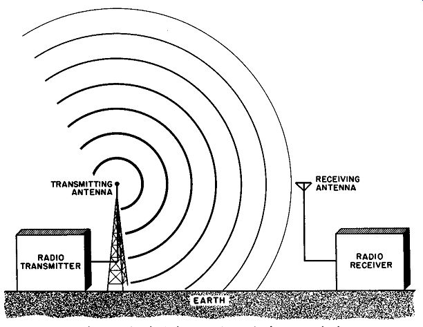
Fig. 1. Radiation of spherical waves in a simple communications system.
2. Wave Motion
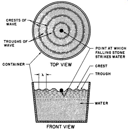
Fig. 2. Waves in water.
An electromagnetic wave travels through space in much the same manner as a wave in a pond of water. Consequently, the action of waves in water can be used as a physical illustration of these aspects of electromagnetic wave motion. When a stone falls into a pond, ripples are formed, as shown in Fig. 2. These waves consist of a series of regularly spaced crests and troughs, which move out ward in concentric circles from the point at which the falling stone disturbed the water. The radii of these circles increase as the distance from the point of disturbance increases. Therefore, these waves are said to travel or propagate radially outward from the point of disturbance.
The distance or separation between any two adjacent troughs or crests is always the same. Since each crest and its adjacent trough form a single wave, the separation between two adjacent troughs or crests is equal to the wavelength and is designated as, (lambda). The crest and trough of a water wave are at different vertical levels.
The difference between the crest (or trough) level and the average level (level in absence of waves) is a quantity known as the wave amplitude.
When a stone is dropped into a pond, the amplitude of the first wave is larger than that of the second wave, the amplitude of the second wave is larger than that of the third wave, and so forth. Thus, the waves produced gradually diminish in amplitude and ultimately disappear.
This action, of course, cannot be directly compared to that of electromagnetic waves, because the electromagnetic wave is produced continuously as long as a radio signal is being transmitted.
When the rate or frequency (times per second) at which waves are produced has the value f, the waves will travel outward at a velocity (V) equal to the product of the frequency (f) and the wavelength (A) . Thus:
The velocity of an electromagnetic wave in air is the same for all frequencies and is nearly equal to 300,000,000 meters (186,000 miles) per second.
Thus a wave alternating at a frequency of 500 kilocycles per second (500,000 cycles per second) has a wavelength = .372 miles or about 1964 feet
3. Radiation
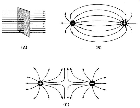
Fig. 3. (A) Faraday's method of mapping field strength based upon the number'
of electric lines passing through a unit square normal to the surface. Electric
lines of force between (B) oppositely charged bodies and (C) bodies having
a like charge.
Radio waves represent a form of electrical energy predicted by James Maxwell nearly a century ago. Basically, they are made up of constantly changing electric and magnetic fields, with the total energy of the wave divided equally between the two.
Michael Faraday proposed a useful method of mapping an electric field to show its direction and magnitude at a given point.
Once the intensity and direction of the field were known, he imagined a unit square drawn perpendicular to the field at that point (Fig. 3A), and a sufficient number of lines cutting through the square to represent the magnitude of the electric field at that point.
These lines of force are said to exist in the direction of the field (note arrowhead) . Faraday explained the attraction and repulsion between charged bodies by assuming that the lines of force are in a continual state of tension (like rubber bands) , and that they tend to repel each other laterally.
In Fig. 3B it can be seen that the lines of force leave the negatively charged body perpendicular to the surface and enter the positive body perpendicular to its surface. Since the lines are repelled from one another and tend to contract, the bodies tend to attract each other. In Fig. 3C the lines emerge from the two positive bodies shown and go to a negative body (too distant to show in the illustration). Mutual repulsion between these lines tends to create repulsion between the two bodies. It should be mentioned that the lines of force are not physical realities, but are used only to illustrate a somewhat elusive concept.
An electric field may be defined in another way. Assume that a capacitor having a plate separation of five meters is charged to a potential of 100 volts (Fig. 4) . Electric lines of force permeate the volume between the plates, and will be everywhere constant in density, save for an insignificant distortion at the ends. It is obvious that if the potential at one plate is zero with respect to - 100 volts at the other plate, there is a change of 100 volts in a distance of 5 meters (or an increase of 100 volts/5 meters = 20 volts per meter).
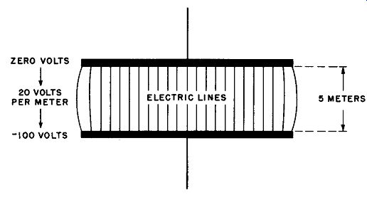
Fig. 4. The electric field of a capacitor.
It should be understood from this that a difference in potential exists between any two different points on a given electric line of force. There need not be a physical source of voltage in the region under consideration; reference to electric lines of force in "free space" specifies their magnitude as a given voltage difference per meter. Electric lines of force are vectors having direction and magnitude. They also represent the direction of force applied to a small positively charged body placed in that field, in accordance with the equation:
E (stat-volts per cm) = F (dynes) / Q (Stat coulombs)
Now if the 100-volt source we have been considering were alternating, a current would flow through the wires connecting the capacitor with the source. The current would charge and discharge the capacitor, causing a polarity reversal during each cycle in accordance with basic theory. What happens inside the capacitor, however, cannot be completely described in terms of elementary electron theory. The idea that a kind of current flows from plate to plate inside the capacitor must be introduced.
It is a physical reality that an alternating voltage applied to a capacitor produces a current that flows into one plate and out of the other. This happens only when the voltage across the capacitor is changing; i.e., when the electric field between the plates is varying in magnitude. James Maxwell proposed that under these conditions, the current entering one plate did not stop, but continued to flow across the space between the plates. Indeed, one of Maxwell's original assumptions (upon which his famous theory of electro-magnetism was based) is that a change in an electric field is equivalent in its electromagnetic effects to an actual flow of current. Maxwell called this current a displacement current; today the term space current is often applied.
Clearly then, a changing electric field always gives rise to a type of current, or equivalent current, that actually flows through space. In accordance with basic theory this space current -- as well as the actual current in the wires -- leads the applied voltage of the electric field in phase by 90 degrees. This concept is important for a mature understanding of the propagation of radio waves.
4. The Magnetic Field
Magnets that are free to move in space behave very much like electric poles in the sense that attraction and repulsion both occur, depending upon the orientation of the poles of the magnets. More over, the magnitude of these forces, like those in an electrostatic field, depends upon similar constants such as pole strength, separation, and the character of the medium in which the magnets are immersed.
The parallelism between electric and magnetic poles immediately suggests that there is a magnetic field in existence in the vicinity of magnetic poles. A magnetic field is often represented by lines of force pointing in the direction of the field, or in the direction of the force exerted upon a unit north pole placed in the field As we shall show later, electric and magnetic fields produced by electric potentials and their accompanying currents are always perpendicular to each other with respect to direction; this inflexible "partnership" is one of the prime tenets of Maxwell's theory of electromagnetic radiations, and has been amply proven in both physical and mathematical terms by countless experiments.
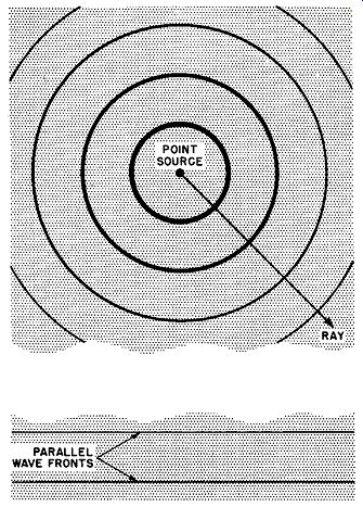
Fig. 5. Spherical propagation from a point source.
5. Electromagnetic Waves
On the basis of classical theory, it can be shown that an accelerating electric charge will always radiate energy in the form of electromagnetic waves. In an antenna, electronic charges (electrons) are made to accelerate, and this is what causes radiation.
If these radio waves arc emitted from a point source (a source so small as to have only mathematical significance) they will expand spherically like a balloon being inflated. (See Fig. 5.) An increment of energy in a specific direction is called a ray. The rays are always perpendicular to the surface of the imaginary balloon, and thus diverge as the balloon increases in size. As the energy expands, its intensity per cubic unit of space must diminish, since the total energy is spread over a larger total volume. At a great distance, the surface of each successive "balloon" is nearly parallel to those of its neighbors. (This explains why radio waves are usually considered parallel to one another, except near the source.) This "surface" is called a wave front, and in relation to any point through which it passes, it may be regarded as a plane surface.
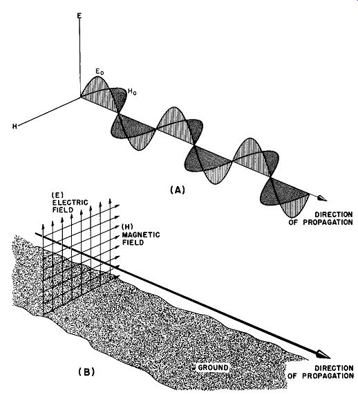
Fig. 6. (A) E and H components of the electromagnetic wave. (B) Vector equivalent.
If we examine a ray of a radio wave, we find that it is made up of electric and magnetic fields. The fields are perpendicular to one another and to the direction of travel (propagation) . The fields vary sinusoidally at the frequency of the source.
The simplest type of electromagnetic wave is shown in Fig. 6.
Such a wave is a polarized wave; that is, the magnetic and electric components do not oscillate in random directions, but are fixed. The polarization of a radio wave is taken as the orientation of the electric vector with respect to the earth. Thus a vertically polarized wave (as shown in Fig. 6) possesses a vertical electric field (E) and a horizontal magnetic field (H) . The vectorial method of illustrating this is shown in Fig. 6B. For most communication purposes, the radio wave is either horizontally or vertically polarized.
A fundamental relationship showing the instantaneous value of the magnetic and electric fields as a function of velocity of propagation, distance from the source, and frequency of oscillation in terms of practical mks (meter-kilogram-second) units is:
(2)
(3)
Where:
H(lnst.) = Instantaneous value of the magnetic vector in amperes per meter.
E (Inst.) = Instantaneous value of the electric vector in volts per meter.
H .. = Maximum value of the magnetic vector.
Eo = Maximum value of the electric vector.
t = Time (in seconds) required for the wave to reach a determined point in space.
f = Frequency in cps.
X= Distance in meters.
C= Velocity of electromagnetic radiation.
(300,000,000 meters per second). The peak amplitude of either field at a given distance from the source may be given as a function of the radiated power:
E0 = 120H0 =60P / r2 (4)
Where:
P = Radiated power in_ watts (joules/sec).
r = Distance from the source in meters.
120-pi and 60 carry the dimensions of ohms.
6. QUIZ
(1) What factors affect the successful use of a radio communication system?
(2) Explain the nature of electromagnetic wave motion.
(3) What is a wavelength?
(4) Explain the meaning of the formula V = lambda x f.
(5) What is an induction field?
(6) How is electromagnetic wave energy radiated?
(7) Define: volts per meter; space current.
(8) Give the fundamental relationship expressing the peak amplitude of either field at a given distance from the source as a function of the radiated power.
(9) The electromagnetic wave is composed of E and H field components.
What is the phase and amplitude relationship between these components?
(10) How does a horizontally polarized wave differ from a vertically polarized wave?