To Check the Audio Amplifier System for Amplitude Distortion
Equipment: Audio oscillator and scope having horizontal amplifier with flat frequency response through the audio-frequency range.
Connections Required: Connect output cable from audio oscillator to audio-amplifier input. Connect vertical-input cable of scope across voice-coil terminals of speaker. Connect horizontal-input terminals of scope to audio-oscillator output cable.
Procedure: Adjust scope controls for diagonal line or Lissajous pattern, as shown in the following. Set audio-oscillator output below overload point of amplifier. Check pattern over audio-frequency range.
Evaluation of Results: When audio system is free from amplitude distortion, the diagonal line, ellipse, or circle displayed on the scope screen will be free from geometrical irregularities. Curvature or kinks in a line display, or flattened regions in an elliptical or circular display, show the occurrence of amplitude distortion.
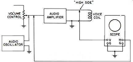
--- Test setup.
Moderate amplitude distortion {audio Negligible amplitude distortion. oscillator frequency varied.
Moderate amplitude distortion and Severe amplitude distortion (overload). phase shift.
NOTE 105
Floating Voice Coil
Inspect the receiver circuit diagram to determine whether the voice coil is grounded on one side or is "floating." If the coil is "floating," ground one side or use a double-ended scope. (See U94.)
+++++++++
U91
To Check the Audio Amplifier for Amplitude Distortion (Motional Impedance of Speaker Eliminated from Pattern)
Equipment: Audio oscillator, load resistor, and scope having horizontal amplifier with flat frequency response through the audio-frequency range (DC scope preferred for very low frequency tests) . Connections Required: Connect output cable from audio oscillator to audio-amplifier input. Disconnect voice coil and substitute 2-watt resistor having a value equal to voice-coil impedance. Connect vertical-input cable of scope across resistor. Connect horizontal-input terminals of scope to audio-oscillator output.
Procedure: Adjust scope controls for diagonal line or Lissajous pattern, as shown in U90. Set audio-oscillator output below overload point of amplifier. Check pattern over audio frequency range.
Evaluation of Results: When audio system is free from amplitude distortion, the diagonal line, ellipse, or circle displayed on the scope screen will be free from geometrical irregularities. Curvature or kinks in a line display, or flattened regions in an ' elliptical or circular display, show the occurrence of amplitude distortion.
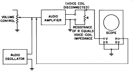
--------- Test setup.
NOTE 106
Motional Impedance Characteristic of Speaker
The difference in patterns observed in U90 and U91 gives the motional impedance characteristic of the speaker. The better the speaker, the more constant is its motional impedance over a wide audio-frequency range.
NOTE 107
Use of Double-Ended Scope
If one side of the voice coil is not grounded or if circuit configuration prevents grounding one side for audio-output tests, use a double-ended scope. Ground scope case to receiver chassis. Connect vertical-input terminals of scope across the double-ended circuit, as shown in U94.
+++++++++
U92
To Measure the Voltage Gain of the Audio Amplifier
Equipment: Audio oscillator and low-capacitance probe.
Connections Required: Apply audio-oscillator output to amplifier input. Connect probe output to vertical-input terminals of scope.
Procedure: Set audio-oscillator output below amplifier overload point. First, connect probe across the amplifier input and then connect probe across amplifier output.
Evaluation of Results: The ratio of vertical deflections at points 1 and 2 in the following illustration gives the voltage gain from the grid of the input stage to the plate of the output stage. Note that this test provides no data on power gain, since input and output impedances are not taken into account in this test.
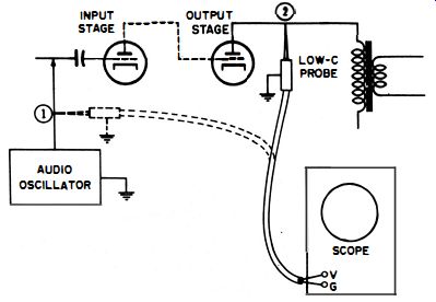
-------- Test letup.
++++++++++++
U93
To Check the Frequency Response of the Audio System
Equipment: Audio oscillator with uniform output over the audio range and scope with flat frequency response (DC scope preferred) .
Connections Required: Connect audio-oscillator output cable to amplifier input. Connect vertical-input terminals of scope across voice-coil circuit.
Procedure: Operate audio oscillator below amplifier overload point. Adjust scope controls for usual sine-wave display.
Vary audio-oscillator frequency while watching scope deflection.
Evaluation of Results: Disregard phase shift and observe only the amount of vertical deflection; horizontal-gain control may be turned to zero. Considerable variation of response is often observed in low-priced receivers.
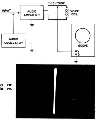
----- Test setup. ------ Pattern obtained in frequency response check (horizontal
gain reduced to zero).
NOTE 108
Effect of Tone Control in Audio-Amplifier Network
Some receivers have a tone control in the audio-amplifier network. The tone control setting affects the frequency response and phase shift over the audio-frequency range.
Hence, this factor must be considered in evaluating amplifier performance.
+++++++++
U94
To Observe Waveforms in Double-Ended Audio Circuits
Equipment: Scope with double-ended vertical input.
Connections Required: Ground scope case to receiver chassis.
Connect vertical-input terminals of scope across the double ended circuit, as shown in the following typical circuit.
Procedure: Same as in single-ended tests.
Evaluation of Results: Same as in single-ended tests.
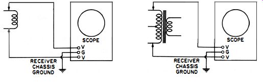
(A) Across floating voice coil. (B) Across push-pull audio output transformer.
Test setup for observing double-ended audio circuits.
+++