To Measure the Rise Time of a Square Wave with a Differentiating Circuit
Equipment: Resistor (75 ohm) , assortment of small capacitors (or trimmer capacitor) , and square-wave generator.
Connections Required: Connect the resistor and a capacitor in a differentiating circuit as shown. Connect the square-wave generator to the input of the differentiating circuit, and connect the scope via a low-capacitance probe to the output. A 75-ohm resistor is suitable for most tests.
Procedure: Using a measured output voltage from the generator (such as 1 volt peak-to-peak), change the value of C by using different capacitors until the output pulse is 65% of the square-wave amplitude. (In this example the pulse would have an amplitude of 0.65 volt peak-to-peak. )
Evaluation of Results: When the capacitor in the differentiating circuit has a suitable value, the 'differentiated pulse is 65% of the amplitude of the applied square wave. The time constant of the differentiating circuit is then equal to the rise time of the square wave, within the limits of practical accuracy. For example, suppose that you find that a 0.00l-mfd capacitor must be used with a 75-ohm resistor. The time constant of this combination is 0.075 microsecond, so the rise time of the square wave is approximately 0.075 microsecond.
This test is based on the fact that the charge on capacitor C (see the following illustration) is decaying while the square wave is rising. Thus the amplitude of the differentiated pulse is related to the rise time of the square wave.
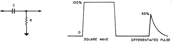
----- Test setup. Input and output of test circuit .
++++++
U96
To Make a Ringing Test of an Inductor or Winding of a Transformer
Equipment: Square-wave generator, pulse generator, or scope that provides a fast-rise test pulse.
Connections Required: Connect coil winding under test to the vertical-input terminals of the scope, as shown in the following sketch. Couple the square-wave or pulse voltage to the coil via a gimmick or a small (fixed or trimmer) capacitor.
Procedure: Advance scope gain and apply sufficient drive voltage to display a convenient pattern height. Set the time base of the scope to obtain the desired waveform expansion. The pattern is automatically synchronized if you use a test pulse from the scope itself.
Evaluation of Results: Count the number of peaks in the ringing waveform from the 100% to the 37% amplitude point; this is the number of cycles. Multiply this number by pi (3.14) . The product is equal to the Q value of the coil at its ringing frequency. If you are using a triggered-sweep scope, you can determine the ringing frequency by noting the setting of the time base. For example, if one cycle of the ringing waveform occupies one centimeter and the time base is set for a sweep speed of one microsecond percentimeter, the ringing frequency is one megacycle/second.
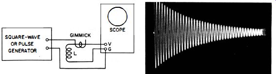
--- Ringing test setup. Typical pattern.
NOTE 109
Lack of Adequate Amplitude in Ringing Pattern
Beginners sometimes have difficulty in obtaining a ringing pattern with adequate vertical amplitude. The cause of this is that the driving square wave or pulse has too slow a rise time. Use a better source if difficulty is encountered. It is not good practice to connect the square-wave or pulse generator directly to the inductor under test because the output resistance of the generator is then shunted across the inductor.
This reduces the Q of the inductor and gives a misleading measurement.
It is best practice to use a gimmick for coupling; the gimmick insures that the inductor is only slightly loaded by the generator. The use of a gimmick reduces the drive voltage to the inductor, so the square-wave or pulse source must have a fast rise.
++++++++
U97
To Measure the Bandwidth of an LC Circuit with a Ringing Test
Equipment: Square-wave generator, pulse generator, or scope that provides a fast-rise test pulse; coil, and capacitor (fixed or variable).
Connections Required: Connect equipment as shown in the follow illustration.
Procedure: Display the ringing waveform obtained with a chosen value of C, and count the number of peaks (cycles) in the ringing waveform from the 100% to the 37% amplitude point.
Compute the ringing frequency (see U96) . Evaluation of Results: Multiply the number of cycles observed by pi (3.14) . This gives the Q value of the LC circuit. Divide the ringing frequency (given by the time-base setting) by the Q value. This gives the bandwidth of the LC circuit with acceptable accuracy. For example, suppose that the Q value of the coil is 50, and the ringing frequency is 1-mhz.; the bandwidth is approximately 20-khz. Note that the bandwidth of a coil and capacitor combination changes when the capacitor is tuned to a different frequency. As shown in the illustration which follows, the bandwidth is equal to the number of cycles between the 0.707 voltage points on the frequency response curve. The 0.707 voltage points are also called the half-power points, or the -3 db points.
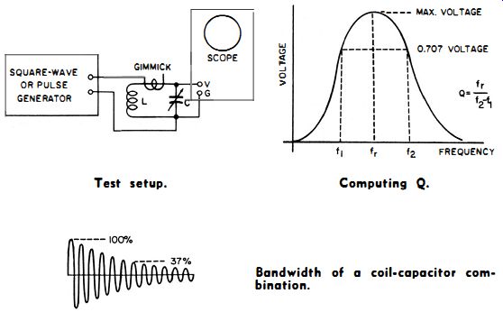
----- Test setup. Computing Q. ----- Bandwidth of a coil-capacitor combination.
++++++++++++
U98
To Make a Square-Wave Test of a Two-Section RC Integrator
Equipment: Square-wave generator.
Connections Required: Connect output from square-wave generator to input of two-section integrator as shown in the following diagram. Connect the scope via a low-capacitance probe to the output of the two-section integrator.
Procedure: Set the square-wave generator and scope controls to obtain a display of the leading edge of the output waveform.
Compare this with the curve in the following chart.
Evaluation of Results: The universal time-constant chart shows the characteristic waveform of a two-section integrator. The waveform normally rises to 50% of maximum amplitude in 2 time constants, and rises to 95% of maximum amplitude in 8 time constants. Note that this assumes a symmetrical circuit, in which both resistors have the same value and both capacitors have the same value. For example, if R of an integrator unit is 10K and C is 0.1 mfd, RC is equal to 0.001 second, or 1 millisecond. If the integrator unit is good the output waveform should rise to 50% of maximum amplitude in 2 RC time constants, which in this case is 2 milliseconds.
This is the most practical method of testing a "package" integrator, because the individual components are not accessible for test.
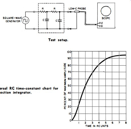
-------- Test setup.
------ Universal RC time-constant chart for two-section integrator.
++++++++
U99
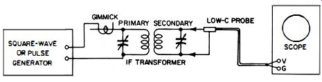
To Make a Ringing Test of an IF Transformer
Equipment: Square-wave generator, pulse generator, or scope with test-pulse output.
Connections Required: Connect the test setup as shown in the following diagram.
Procedure : Advance the scope gain and apply sufficient drive voltage to obtain a convenient pattern height on the scope screen. Use a square-wave frequency and a horizontal sweep rate that produce several beat intervals, as shown in the following photo. (If you use a test-pulse output from the scope, the pattern will be automatically synchronized.) Adjust the trimmer capacitors of the IF transformer for (1) maximum pattern amplitude and (2) well-defined zero-beat points, as shown in the photo.
Evaluation of Results: Beginners are advised to limit themselves to comparative ringing tests of IF transformers. However, a few of the pattern characteristics may be noted. An IF transformer has two resonant frequencies, which result from the mutual inductance indicated in the equivalent circuit; these two frequencies beat together to produce the ringing pattern.
If we call these ringing frequencies fl and f?, the beat frequency is equal to f2 - f1 . The center frequency of the IF transformer is equal to the ringing frequency of the pattern, (f1 + f2) /2. If a sweep-frequency generator signal is applied, you will see fl and f:l as the hump frequencies indicated. The ringing frequency in the pattern corresponds to fo. The ringing pattern decays because of the AC resistances of the primary and secondary. The rate of decay is determined by the Q values of the windings. Note that you must employ a fast-rise square wave or pulse to obtain the ringing pattern illustrated.
--------- Test setup.
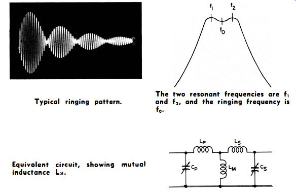
-------- Typical ringing pattern. The two resonant frequencies
are f1 and f2, and the ringing frequency is fo.
+++++++
U100
To Display a Waveform on Expanded Sweep
Equipment: Scope with expanded sweep function.
Connections Required: Apply waveform voltage under test to vertical-input terminals of scope.
Procedure: Set scope controls for expanded-sweep display, as shown.
Evaluation of Results: Waveform details become apparent on expanded sweep. For example, in the following photo, expanded sweep gives a useful evaluation of the noise voltage on the trailing edge of the pulse. Note that the rise is so fast, it is invisible.
---- Test setup.
------ A pulse waveform displayed using conventional sawtooth sweep.
The same waveform displayed using the expanded sweep function.
++++++
U101
To Measure the Phase Angle Between Two Sine-Wave Voltages, Such As the Input and Output of an Amplifier
Equipment: Audio oscillator and load resistor.
Connections Required: Drive amplifier with audio oscillator.
Terminate amplifier in correct load with resistor. Feed amplifier input voltage to horizontal-input terminals of scope. Feed amplifier output voltage to vertical-input terminals of scope.
Procedure: Make tests at frequencies within flat frequency response range of scope amplifiers. Operate scope on horizontal-input function. Adjust gain controls for suitable pattern size.
Evaluation of Results: An inclined line, ellipse, or circle appears on the scope screen. The ratio of dimensions shown gives the sine of the phase angle.
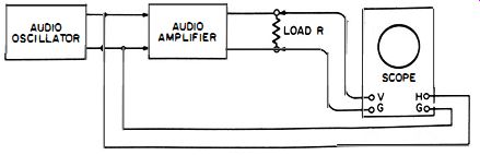
---------- Test setup.
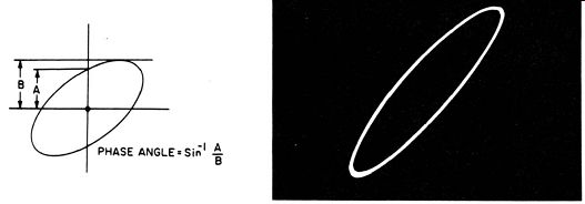
----- Method of computing phase angle.
Waveform observed on scope in fore going test.
Values of the sine for angles from 0° to 180°.
+++