AMAZON multi-meters discounts AMAZON oscilloscope discounts
Now it is time for a practice session, where all you have learned can be applied to solving actual problems. All case histories were written from actual experience; they were not simply "arm-chaired" from theory.
The experiences are described step by step, beginning with the customer complaint and ending with the method of repair.
The troubles described will not necessarily be those most often encountered; instead, they are ones which can cause the most difficulty.
The following troubles are described to demonstrate the testing procedures in this guide, and to assist you with some of the more elusive troubles encountered in transistor radios.
CASE HISTORY NO. 1-THE DEAD PORTABLE
Type of Radio: Transistor AM portable Transistors: 6 Stages: Converter, 1st IF, 2nd IF, driver, push-pull output Customer Complaint: "The radio doesn't play." Test Procedure:
1. The radio was turned on and the batteries checked.
Result-Normal voltage and current drain.
Meaning-The batteries are good, and the electrolytics are not shorted.
2. The radio was observed closely.
Result-It was completely dead, except for a slight pop as it was turned on and off. There were no obvious loose connections or broken conductors.
Meaning-The speaker was probably all right, and the circuit board apparently was not broken.
3. The volume control was turned to its maximum position, and the audio system was checked by the body click test.
That is, with one hand on the chassis and the other holding a metal probe, the probe was used to tap the base lead of the driver transistor. The body resistance thus prevented the transistor from being grounded directly.
Result-A click was heard.
Meaning-The audio system was functioning.
4. The same procedure was applied to the 1st IF base lead and the converter collector lead.
Result-Nothing was heard at either point.
Meaning-The trouble was in one of the IF stages, since no signal could be sent through them.
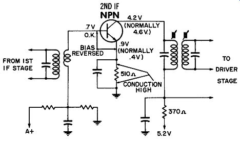
Fig. 10-1. Abnormal voltages in this stage are caused by a leaky transistor.
5. Voltages were read on the IF transistors.
Result-The 1st IF stage measured all right, but the 2nd IF transistor had incorrect conduction and bias voltages (see Fig. 10-1). Meaning-The transistor was drawing a lot of collector current, but the bias voltage was reversed from normal. This meant the transistor must be partially shorted between emitter and collector.
6. The transistor was removed from the radio and checked.
Result-The leakage resistance between emitter and collector (with base floating) dived rapidly toward zero.
Meaning-The transistor was very leaky.
Conclusion When some very simple procedures were followed, this case was solved in a few minutes. Systematic stage isolation plus voltage readings paid off.
A minimum of test equipment was used-the eyes and ears, a small probe, and an ohmmeter.
CASE HISTORY NO. 2-THE DROPPED RADIO
Type of Radio: Transistor AM portable Transistors: 6 Stages: Converter, 1st IF, 2nd IF, driver, push-pull output Customer Complaint: "The radio is dead-it was dropped." Test Procedure:
1. The radio was turned on and given a listening test.
Result-Nothing was heard.
Meaning-Not conclusive.
2. The batteries were checked.
Result-Battery voltage normal; battery current nor mal or slightly below.
Meaning--The batteries were good, and no filters were shorted.
3. The radio was given a good visual check. The printed side of the board was pointed downward and soldered to the front plate. The transistors were on top, however, and easily accessible.
Result-No cracks or other obvious faults were noted.
Meaning-Not conclusive.
4. The base lead of the audio driver transistor was given the click test.
Result-No click was heard.
Meaning-The audio system was not working.
5. Voltage readings were taken on the audio transistors.
Result-All driver transistor voltages read about the same (see Fig. 10-2). The collector voltage was very high.
Meaning-The collector lead may be open, allowing the collector to assume the emitter potential.
6. The radio was given another careful visual check in the area of the driver transistor.
Result--A small crack was observed which extended through to the copper conductor, between the driver collector lead and the collector transformer.
Meaning--The collector circuit was open.
Conclusion Close visual observation is very valuable; but when the defect cannot be seen, routine isolation and voltage checks should be made.
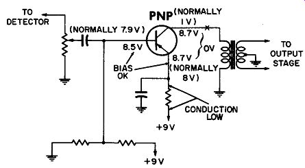
Fig. 10-2. Improper voltages resulting from an open in the collector circuit.
CASE HISTORY NO. 3--INTERMITTENT AND WEAK OUTPUT
Type of Radio: Transistor AM portable Transistors: 9 Stages: RF, oscillator, mixer, 1st IF, 2nd IF, AGC, audio driver, and push-pull output.
Customer Complaint: "The radio fades at times." Test Procedure:
1. The radio was turned on.
Result-Normal reception.
Meaning-Not conclusive.
2. The radio was jarred to see if it would fade.
Result-The signal suddenly became weaker.
Meaning-The radio was intermittently weak.
3. The battery voltage and current were checked.
Result--Normal voltage and current.
Meaning--The batteries weren't weak or making poor connection; the electrolytics weren't shorted.
4. The circuit board was tapped at various spots, and so were the components.
Result--The radio seemed to be sensitive to jarring around the IF section.
Meaning--The IF section should be checked.
5. A close observation was made of that area.
Result--Nothing was found.
Meaning--No loose connections were visible.
6. The radio was jarred again until its output became very weak. Gain checks were then made.
Result--The IF section was very weak.
Meaning--Further check should be made in that section.
7. Voltage were read in the IF stages.
Result--All were normal.
Meaning--DC conduction was normal.
8. A pencil soldering iron was applied to the IF transformer terminals.
Result--The last IF was very sensitive to heat, and the sensitivity became normal when the radio was touched.
Meaning--The transformer was intermittent.
Conclusion
An intermittent open capacitor in the base of an IF trans former does not usually cause the development of an incorrect voltage. This goes back to the rule that if all voltages are normal, the defect is probably an open capacitor or a detuned circuit. In this instance we had both because the capacitor was part of a tuned circuit. So, when it opened, it detuned the transformer. The result was an extremely weak radio, but no incorrect voltages!
CASE HISTORY NO. 4--THE HIGH-DRAIN PORTABLE
Type of Radio: Transistor AM portable Transistors: 6 Stages: Converter, 1st IF, 2nd IF, audio driver, push-pull out put.
Customer Complaint: "The radio is dead." Test Procedure:
1. The radio was turned on.
Result-It was dead.
Meaning-Not conclusive.
2. The battery voltage was checked with the radio turned on.
Result-It was 1.2 volts (instead of 9). Meaning-It was much too low.
3. The battery current was checked.
Result--It was 60 milliamperes (instead of 6).
Meaning--There was a short on the "A+" line.
4. The printed circuit was closely observed for a solder short.
Result--Nothing unusual was noted.
Meaning--No apparent short in the circuit.
5. The electrolytic was checked with an ohmmeter on the Rx1 scale.
Result--It was 40 ohms.
Meaning--It was much too low.
6. The electrolytic was disconnected and checked again.
Result--It was still about 40 ohms.
Meaning--The capacitor was defective.
Conclusion Much time was saved by checking the battery voltage and current first.
CASE HISTORY NO. 5--CASE OF THE UNUSUAL SHORT
Type of Radio: Transistor AM portable.
Transistors: 9 Stages: RF, oscillator, mixer, 1st IF, 2nd IF, AGC, audio driver, push-pull output Customer Complaint: "Dead radio."
Test Procedure:
1. The radio was turned on.
Result--It was completely dead-not even a "hiss." Meaning-Not conclusive.
2. The battery voltage and current were checked.
Result--Both were within normal limits.
Meaning--Batteries O.K.; electrolytic not shorted.
3. Stage gains were checked with a noise generator.
Result--At the base of the audio driver-good signal.
At the base of the 1st IF-no signal. At the base of the mixer-extremely weak signal.
Meaning-The trouble is in the IF section, because a good signal normally is heard at the 1st IF base.
4. Voltages were checked in the IF stages.
Result-The 2nd IF voltages were normal, but the 1st IF voltages were not (see Fig. 10-3). Meaning-There was a defect in the 1st IF base circuit, because the base voltage was much too high.
5. On a hunch, we checked the collector voltage of the pre ceding stage.
Result-The mixer collector and the 1st IF base voltages (Fig. 10-3) checked the same.
Meaning-1st IF transformer T1 was shorted between the primary and secondary.
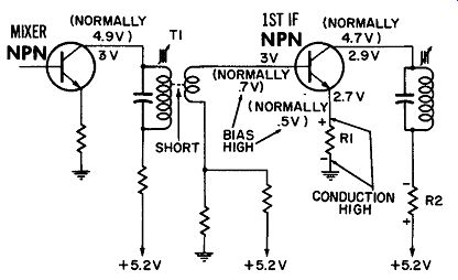
Fig. 10-3. Voltages caused by a short between the primary and secondary
windings of the 1st IF transformer.
Conclusion
An ohmmeter confirmed the defect. The base voltage was much too high because of the shorted transformer, and thus caused the 1st transistor to conduct much too heavily. As a result, the collector voltage dropped, and the emitter voltage rose because of the voltages produced by the current flow through R1 and R2.
By isolating the trouble to the IF section and then properly analyzing the voltages, we rapidly found the cause. (We also could have isolated the trouble by click testing.)
CASE HISTORY NO. 6--AM-FM WITH NO AM
Type of Radio: AM-FM table model
Transistors: 11
Stages: FM RF, FM mixer, FM osc., AM osc., 3 dual-purpose FM IF amps, audio amplifier, audio driver, push-pull out put.
Customer Complaint: "Dead on AM, O.K. on FM." Test Procedure:
1. The radio was turned on.
Result--AM dead, FM O.K. Meaning--The audio system is working, and so is FM tuner. Trouble must be in one of the dual stages or AM oscillator.
2. On a hunch, another radio was placed next to the defective one, and tuned to a station near 1600 khz. The defective radio was "Rocked" between 1000 khz and 1400 khz.
Result-The oscillator "beat" signal, or "birdie" was not heard.
Meaning-The AM oscillator was probably not working. (Further checks revealed that the bias on the oscillator was high, and did not change when the radio was tuned. A new AM oscillator transistor was tried and set returned to normal.) Conclusion By careful inspection and listening to both bands, it is easy to isolate most troubles rapidly in AM-FM radios.
CASE HISTORY NO. 7-THE FADER FIXED FAST
Type of Radio: AM auto radio Transistors: 6 Stages: RF, converter, IF, AF amp, driver, output.
Customer Complaint: "Radio fades when I get out of town or near buildings." Test Procedure:
1. The radio was still in the car. It seemed weak on out of town stations; locals O.K. Meaning-The antenna trimmer could be off "Peak."
2. The radio was tuned to a very weak station near 1400 khz.
The trimmer was rocked back and forth until the station was loudest.
Result--The sensitivity improved tremendously.
Conclusion
On a weak or fading auto radio complaint, always check the antenna trimmer before removing the radio from the car. (If AM-FM radios, make sure antenna height is 30 inches above fender for best FM reception). The antenna trimmer is only adjusted on AM; it is not in the circuit on FM.