AMAZON multi-meters discounts AMAZON oscilloscope discounts
FM is not ideally suited for automobiles, but it is becoming very popular because of the excellent programming, fidelity, and noise-free reception. It does offer considerable relief from the overcrowded AM band, but the range is definitely limited.
The FM band (88-108 mhz) is actually between Channel 6 and 7 TV channels. Proof of this can be easily seen in areas which have a channel-6 TV station. The audio can be heard just below 88 mhz on many FM receivers.
Broadcasts in this frequency range are "line of sight"--the receiving antenna must "see" the transmitting antenna. In homes where the antenna is on the roof, it is possible to obtain range from high powered stations of 100 miles or more. In automobiles, a different situation exists where the antenna is virtually half a rabbit ears operating close to the ground. The range from a typical 50,000-watt station is 25 miles (Fig. 9-1). Beyond this distance, flutter can be expected. Lower-power stations exhibit flutter at less distance.
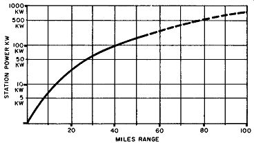
Fig. 9-1. Range versus FM station power for average condition in flat terrain.
The length of the car antenna is very important when listening to FM. To obtain maximum signal pick-up, it should be extended to exactly 30 inches above the fender. This 30 inch length is ¼ wavelength at the center of the FM band.
This matches the antenna to the radio, since the AM antenna trimmer is switched out of the circuit and has no effect on FM signals. Failure to use the proper antenna height increases the flutter effect.
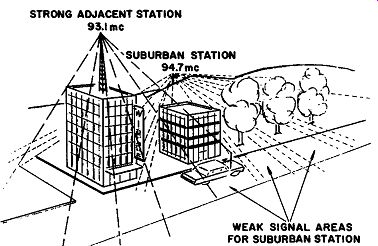
Fig. 9-2. How low antenna height, buildings, etc. limit FM range.
Other causes of flutter are terrain (hills, etc.) and buildings (Fig. 9-2). Not only do they block the signal as the car moves by, but they cause multipath reception. That is, signals from the station are reflected by the buildings and arrive at the car antenna a fraction of a second later than the direct signal.
If the two arrive in phase ( depending on the position of the car), they add, but when the car moves and they arrive out of phase, they cancel each other. This is flutter-a momentary drop out, or loss, of signal.
SCHEMATIC FAMILIARIZATION
AM-FM auto radio circuits are very similar to the household AM-FM radios described earlier. For this reason, the circuits should look familiar and will only be discussed briefly.
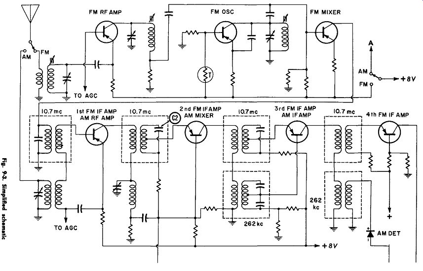
Fig. 9-3 shows a simplified AM-FM auto radio schematic.
At the top of the schematic are three tuner stages-the FM RF amplifier, FM oscillator, and FM mixer. Power is switched to the tuner when the band switch is in the FM position, and, at the same time, the antenna is connected to the FM-RF input. The station signal is amplified and sent to the FM mixer, where it meets the signal generated by the FM oscillator.
The difference of those two signals is 10.7 mhz.
The 10. 7 mhz IF signal is coupled to the 1st FM-IF stage, which is a dual purpose amplifier (it doubles as the AM-RF amplifier). After amplification by two other dual purpose stages and the 4th FM-IF, it is sent to the FM detector and three direct coupled audio amplifiers: AF-1, AF-2, and the power output stage.
The individual stages and their functions are:
FM-RF Amplifier FM Oscillator FM Mixer 1st FM-IF AM-RF Amplifier AM Oscillator 2nd FM-IF Amplifier AM Mixer 3rd FM-IF Amplifier AM-IF Amplifier 4th FM-IF FM Detector AM Detector AF-1 AF-2
Amplifies the FM signals.
Generates a signal 10. 7 mhz higher than the station signal.
Produces the 10.7 -mhz IF signal.
Amplifies the 10.7 -mhz signal.
Amplifies the AM signals.
Generates a signal 262 khz higher than the AM station signal.
Amplifies the 10.7 -mhz signal.
Changes the AM signals to IF (262 khz) (assisted by AM osc.)
Amplifies the 10.7 -mhz signal.
Amplifies the 262- khz signal.
Amplifies the 10.7 -mhz signal.
Changes the FM signal to audio.
Separates the audio from the 262 khz signal.
Amplifies the audio.
Further amplifies the audio.
Output Builds sufficient audio power to drive the speaker.
The block diagram in Fig. 9-4 shows the path the signal takes through each stage. Keeping the block diagram in mind is most helpful in troubleshooting.
TROUBLESHOOTING THE RADIO
All that has been learned in previous sections can be applied to this radio. All of the tools for localizing the trouble to one section of the radio and measuring conduction and bias of transistors in that section should be used in troubleshooting AM-FM auto radios.
If the radio is in the car, the trouble should first be isolated to the radio or one of its supporting components before it is removed.
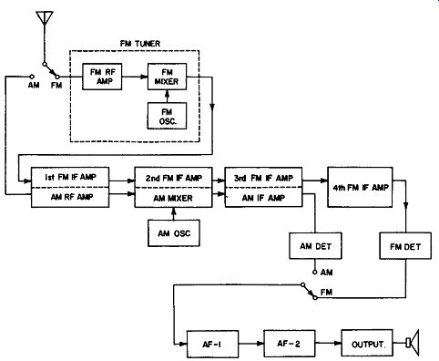
Fig. 9-4. Block diagram of a typical AM-FM auto radio.
Checking the Radio in the Car
The antenna, fuse, and speaker can be checked in the same manner as the straight AM auto radio discussed in the previous section was checked.
Important Points to Remember:
1. The antenna height should be adjusted for 30 inches.
Reason: To minimize flutter on FM.
2. The antenna trimmer should be adjusted for maximum volume while listening to a weak AM station or noise near 1400 khz. Reason: To minimize fading, station mixing, and whistles on AM.
3. No "thump" when power is applied indicates an open fuse, defective speaker, or defective audio system.
4. Owners who have FM in their home and complain of FM flutter when operating their car radio may not under stand the normal range limitations of automobile installations. Take a test ride and compare with other FM car radios.
Checking the Radio on the Bench The following are important points to remember when checking any AM-FM auto radio on the bench:
1. Use the "thump" test to check the audio system.
2. Listen to the radio on both AM and FM. If the FM only is dead, trouble is probably in one of the stages which operates during FM only (FM tuner, 4th FM-IF amplifier, or FM detector). If AM only is dead, the trouble is probably in one of the stages which operates during AM only (AM oscillator or AM detector) . If AM and FM are dead, the trouble is probably in one of the dual-IF stages or the audio system.
3. Noise generators work on AM only. If set is dead on both bands, troubleshoot on AM.
4. Conduction checks are made with no signal entering the radio (antenna disconnected). To check conduction, measure the voltage across emitter resistor; except, in output stage use collector voltage to ground.
5. Normal transistor bias is .2 volt for PNP germanium units and .6 volt for NPN silicon units ( except oscillators, which vary with tuning). Locating Troubles Which Affect Conduction Let's take some typical troubles and see how they make the radio react and how we track them down.
Note how the indications lead you right to the trouble, provided the basic tools of troubleshooting are employed.
If the fuse resistor in the output stage is open:
1. The radio will be dead on both AM and FM.
2. There will be no thump as the radio is turned on.
3. There will be no noise whatever as the volume control is rotated.
4. There will be no voltage at the output collector ( conduction test).
5. There will be little, if any, bias on the output transistor (pointing to trouble in base or emitter circuit).
6. The resistance of fuse resistor will measure very high in one direction of ohmmeter (R X 1).
If the ohmmeter leads are reversed, the reading will be low due to the low resistance of the transistor diode. This shows the importance of always taking two readings in transistor circuits.
If the AM oscillator transistor is open:
1. The radio will be OK on FM; dead on AM.
2. It will have the normal "turn-on thump."
3. When switched to AM, a noise generator will work all the way back to the AM antenna.
4. No whistle (oscillator signal) will be heard in a nearby radio when this radio is tuned.
5. There will be no voltage across the AM oscillator emitter resistor (conduction test).
6. The bias of AM oscillator will be 1.1 volt (high) .
7. The emitter diode resistance will be high in both directions of meter (R X 100 range) . If the 3rd FM-IF amplifier (AM-IF amplifier) transistor is leaky:
1. The radio will be weak on AM and FM.
2. It will have the normal "turn-on thump," and the output collector voltage will be normal.
3. The voltage across all IF emitter resistors will be normal, except the AM-IF amplifier stage, which is above normal.
4. The bias on the AM-IF amplifier will be low or reversed ( depending on how leaky the transistor is).
Locating Troubles Which Don't Affect Conduction
If the audio coupling capacitor C1 is open:
1. The radio will be dead on AM and FM.
2. It will have the normal "turn-on thump."
3. The collector voltage of the output stage ( conduction)
will be normal.
4. There will be no volume control noise.
5. No output will be obtained when the noise generator is placed at the volume control.
6. A loud output will be obtained when the noise generator is placed at the AF-1 base.
If one of the diodes in the FM detector is open:
1. The radio will be distorted on FM; AM OK
2. It will have the normal "turn-on thump."
3. The collector voltage of the output stage (conduction) will be normal.
4. All conductions and biases will be normal.
5. The voltage between points X and Y will not be zero, as it should be in a balanced detector. If the 10.7 -mhz IF capacitor C2 is open:
1. The radio will be dead or very weak on FM; AM OK
2. All audio checks will be good.
3. With volume control turned up, there will be no "FM hiss."
4. All transistor conductions, biases, and other voltages will be normal.
5. An FM signal injected at the 1st FM-IF amplifier collector will be dead or very weak.
6. An FM signal injected at the 2nd IF amplifier collector will be loud.
7. The IF coil connected across C2 cannot be aligned.
From the foregoing, it can be seen that an FM signal generator comes in handy when troubleshooting AM-FM radios, especially when FM reception is weak. Also, it is sometimes necessary to make a good, sharp alignment of the FM auto radio to minimize flutter. The radio needs all of the sensitivity it can get to help overcome the poor reception conditions in the car.
ALIGNING AM-FM RADIOS
Since alignment of individual models is described in service manuals and other books, it will only be discussed very briefly here. There are some things peculiar to AM-FM auto radios which should be mentioned.
Fig. 9-5 shows the usual hook-up for alignment. The FM signal generator should be crystal controlled (such as the Heath Model FM0-1 or equivalent) and is generally connected at the antenna of the radio. The output meter is connected to one side of the ratio detector output.
Difficulties often encountered are:
1. The IF peaks are not sharp.
Solution--keep the signal level of the FM generator low (so that the output meter in Fig. 9-5 reads about 0.5 volt).
2. When attempting to align the tuner, the FM generator output cannot be attenuated, resulting in broad peaks or no peaks at all.
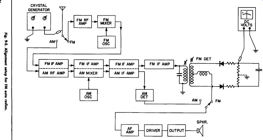
Fig. 9-5
Other faults in the FM detector circuit will cause an unbalanced condition and distortion; for example, an open or detuned ratio detector coil.
Solution-change one of the generator crystals to 9 mhz, and use its harmonics (90 mhz, 99 mhz, 108 mhz) for tuner alignment. A generator with two crystals (9 mhz for tuner alignment and 10.7 mhz for IF alignment) makes an excellent instrument.