AMAZON multi-meters discounts AMAZON oscilloscope discounts
After isolating the trouble to a stage or section of the radio, such as the IF, audio, or converter, we are ready to pinpoint the actual cause. This can best be done by analyzing the voltages at the transistor elements in that section.
It is easy to read the various voltages and compare them with those on a schematic; but unless the troubleshooter knows the meaning of each voltage, he will be unable to determine anything from them. This section is devoted to normal transistor voltages--what they mean and how they are formed.
The following section deals with incorrect voltages and their meanings.
The amount of voltage in the battery or power supply is one factor which determines how much voltage will be found at the various transistors.
This is why it is important to always check the battery voltage first, because if it is low, all transistor voltages will be low also. They will not correspond to the voltages listed on the schematic, since the later are almost always taken with fresh batteries.
Also, weak batteries can cause all sorts of troubles, including a weak, dead, or distorted radio, or even one with weird oscillations or motorboating sounds.
COMPARISON OF TUBE AND TRANSISTOR ELEMENTS
The emitter in a transistor (Fig. 5-1A) emits current carriers; the cathode in a vacuum tube (Fig. 5-1B) emits current carriers. Therefore, the emitter and cathode have a lot in common-the same basic purpose.
The base element in the transistor controls the current flow through the transistor, and the grid in the tube controls the electron flow through the tube. Therefore, they, too, have something in common. The signal is fed in at this point in most tube and transistor circuits.
The collector of the transistor collects the current carriers sent out from the emitter. The plate in a vacuum tube has the same function-to collect the electrons which come from the cathode. The signal is usually taken off ( coupled) from this element and sent to the following stage.
(A) Transistor. (B) Vacuum tube.
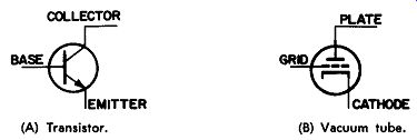
Fig. 5-1. Comparison of the elements.
One of the major differences between tubes and transistors is in the method of emitting current carriers from the cathode or emitter. The tube has a filament to "boil" electrons out of the cathode. But the transistor has no such filament. It uses a small forward bias voltage between base and emitter to start current flowing. This requirement in the transistor leads to the second major difference, the much lower input resistance in the transistor. The small forward bias voltage on the transistor causes a much lower resistance between base and emitter than the tube has between. grid and cathode. Most tubes can have zero voltage between grid and cathode--or even a negative bias--and still conduct, because the heater is continuously "boiling" electrons out of the cathode. With this reversed voltage on the grid, no grid current will flow and the input resistance of the tube will be very high. In the transistor, however, a small base current does flow in order to make the current carriers start moving toward the collector; the input resistance is quite low because of the presence of electrons in the emitter to base region. A measurement of this low resistance is one test we will make later when we talk about testing transistors.
NPN TRANSISTORS
The basic NPN circuit is shown in Fig. 5-2A; Fig. 5-2B shows a similar vacuum-tube circuit. In both examples, the positive pole of the battery is connected to the element which attracts and collects electrons, and the negative pole to the one which emits them. In both examples, the electrons travel out of the negative pole, up through the tube or transistor, and into the positive pole of the battery, making the complete circular path shown by the arrows. Since the emitter is grounded, there is no voltage on it with respect to ground (Fig. 5-3A). The +10 volt potential is applied directly to the collector, and that's what is being measured there.
A quick glance at the input circuit tells us there is a difference between the vacuum-tube (Fig. 5-3B) and transistor circuits. The grid of the tube is tied directly to ground because it needs no bias voltage to make it conduct. The transistor base lead, however, is connected to a voltage divider which, in a sense, replaces the filament the transistor doesn't have. This puts the base at a slightly positive voltage with respect to the emitter; so a small base current flows. This base current is usually so small it can be neglected for troubleshooting purposes. But after being amplified by the transistor, a larger readable collector current is produced.
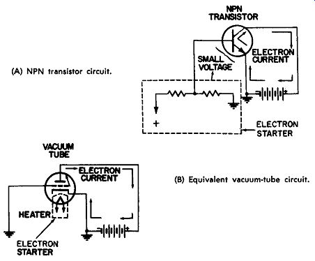
(A) NPN transistor circuit. (B) Equivalent vacuum-tube circuit.
Fig. 5-2. The basic circuit.
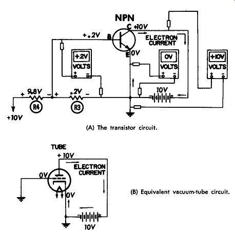
(A) The transistor circuit. (B) Equivalent vacuum-tube circuit.
Fig. 5-3. Voltages present at various points within the circuit.
(A) The circuit. (B) Equivalent vacuum-tube circuit.
Fig. 5-4. Adding an emitter resistor.
Effect of Emitter Resistor
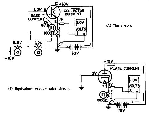
In Fig. 5-4A an emitter resistor, R1, similar to the cathode resistor in a tube circuit, (Fig. 5-4B) has been added. Since the output current travels through these resistors, a voltage drop is produced across them. With the electrons flowing up through R1, as shown by the arrows, the bottom becomes negative and the top positive (Rule: the end where electrons enter a resistance becomes negative with respect to the opposite end.) This gives us a positive voltage on the emitter or cathode when the meter is placed between that lead and ground. This is nothing new, for we have often been able to tell whether a tube is conducting by its cathode voltage (provided a resistor is used in the cathode circuit). The next question is, "How much voltage will there usually be across this resistor?" It depends on how much current is flowing, and on the value of the resistor. Ohm's law states that the voltage across a resistor is equal to the current flowing through it, multiplied by its resistance, thus, if R1 remains constant, the voltage will be directly proportional to the amount of current flowing through it.
When the current increases, so will the voltage across R1.
If no current is flowing in the circuit, there will be no voltage across R1.
Effect of Collector Resistor
In Fig. 5-5A, collector resistor R2 has been added. In Fig. 5-5B, a plate resistor of the same value is connected in series with the plate lead. It has been common practice in vacuum tube circuits to judge the plate current by the voltage across the plate resistor, R2, or by a comparison of plate and battery voltages. In Fig. 5-5B, electrons travel from cathode to plate in the tube, down through resistor R2, and the battery, and -up through cathode resistor R1 as they make their way back to their "home base," the cathode. This means that although the electrons traveled -up through R1, they flow down through R2, producing a negative voltage across R2. The 1.0-volt drop across R2 is subtracted from the battery voltage, leaving only 9 volts on the plate. This is another indication that plate current is flowing. Otherwise, the plate voltage would be 10 volts because, with no current flowing through R2, no voltage will be dropped across it ( voltage drop equals current times resistor value, which would be zero times 1,000, or zero). This method of estimating DC output current works fine except for one hitch-in low-voltage circuits, the plate resistor is usually a coil with insufficient resistance to cause a noticeable voltage drop.
The same principles hold true in Fig. 5-5A, the only difference being that the electrons are flowing through a transistor instead of a tube. This makes no difference as far as the resistors are concerned-if the same current flows, the same voltages will be produced.
Electrons leave the emitter, travel through the transistor to the collector, then go down through R2, and the battery, and up through R1 to the emitter, as shown by the arrows.
This produces, across R2, a negative voltage which is subtracted from the battery voltage to leave 9 volts at the collector. If no collector current were flowing, there would be no voltage across R2 and the collector would read the full 10 volts.
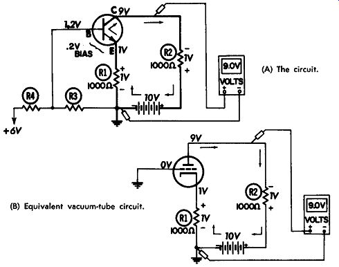
(A) The circuit. (B) Equivalent vacuum-tube circuit.
Fig. 5-5. Adding a collector resistor.
Since we know that all voltage drops in a series circuit must add up to the battery voltage, one might wonder where the other 8 volts are. There is 1 volt across R1 and 1 volt across R2; the remaining 8 volts are found across the transistor, from emitter to collector. A voltmeter placed between the emitter and collector in Fig. 5-5A would read 8 volts. The voltage between emitter and base would read about 0.2 volt, the base voltage being set primarily by voltage divider R3-R4.
Estimating Collector Current
It was previously stated that the voltage drop across R1 and R2 depends on the amount of current flowing through them the more the current, the greater the voltage drop. Thus, current is directly proportional to the voltage produced. We also know that the higher the resistance is in a circuit, the lower the current will be for a given battery voltage. This means the current is inversely proportional to the resistance.
Now let's figure the value of the collector current in Fig. 5-5A. The current through R1 is equal to 1 volt divided by 1,000 ohms, or 0.001 amp. To convert amps to milliamperes, move the decimal three places to the right; so the answer is 1 milliampere. The same figures hold true for the current through resistor R2, because its resistance and the voltage across it are the same. (A very small base current flows through emitter resistor R1, but it is too small to add any noticeable voltage across R1.)
(A) In a transistor circuit. (B) In a vacuum-tube circuit.
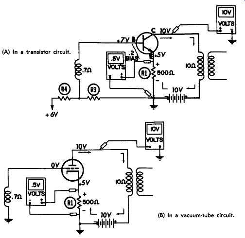
Fig. 5-6. Replacing R2 with a transformer.
As in vacuum-tube circuits, a very low-resistance trans former is sometimes used in place of R2. If so, very little voltage will be found across the transformer.
Effect of Collector Transformer
Fig. 5-6A shows a circuit where the collector or plate resistor (R2) has been replaced by a transformer. Assuming the same current of 1 milliampere (0.001 ampere) is flowing in the circuit, there will be no readable voltage across the trans former because this multiplies out to only .01 volt-so small it can be considered as zero. The collector and plate voltages now read essentially the full 10 volts because there is no noticeable drop in the positive battery lead.
Note also that the value of the emitter resistor in Fig. 5-6A and the cathode resistor in Fig. 5-6B have been changed.
Assuming the collector current is adjusted to about the same as before, or 1 milliampere, the voltage drop across R1 will now decrease to half of what it was before. This is true be cause the voltage across R1 is equal to the current times the resistance of R1; if the resistance goes down and current re mains the same, voltage is bound to go down. Emitter resistors vary in size, depending on the circuit design and the amount of stabilization needed. Common values are from 100 to 2,200 ohms in low-power transistor circuits. Transformer resistances also vary widely. Audio transformers usually have sufficient resistance to produce a voltage drop in the collector circuit, whereas RF and IF coils do not.
The addition of a transformer coil in the base lead has no affect on any of the voltages because the coil usually has a very low resistance (0.7 ohm for the one in Fig. 5-6) and there is practically no current flowing through it.
Voltages Between Elements
In most instances the voltages from one transistor lead to another mean more than the ones to ground, as will be seen in the next section. The difference between base and emitter, which we know as the transistor "bias voltage," is extremely important. The transistor cannot operate properly without it (except in some converter, oscillator, detector, and special push-pull circuits). Fig. 5-7 shows the normal element-to-element voltage relationship found in most amplifier circuits. If the transistor is an NPN unit, the negative lead of the voltmeter is placed on the emitter; and the positive lead is touched first to the base and then to the collector lead. In other words, first the voltage between base and emitter is checked, and then the one between collector and emitter. Since the base-to-emitter voltage, or bias, is usually quite small, it should be read on the low-voltage DC scale. Notice that the bias for a germanium transistor (Fig. 5-7A) is less than that for a silicon transistor (Fig. 5-7B). The collector-to-emitter voltage should be larger, its value depending on the battery voltage, the resistance in the emitter and collector circuits, and the amount of collector current.
Assuming the NPN transistor is in a typical amplifier circuit, with a small forward bias between base and emitter, the base voltage will be slightly positive with respect to the emitter; the collector voltage will be much more positive. In both instances, the emitter is used as a reference instead of ground.
Here is an easy way to remember which meter lead to place on the emitter-it is the same as the first letter in the transistor type, NPN. We will find out later that, in PNP circuits, the positive meter lead is placed on the emitter-corresponding, of course, to the first letter in PNP.
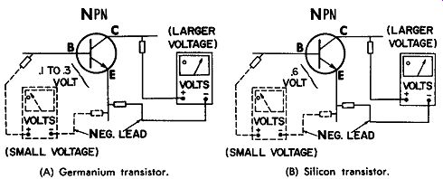
(A) Germanium transistor. (B) Silicon transistor.
Fig. 5-7. Typical element-to-element voltage relationship in a basic transistor amplifier circuit.
When troubleshooting a stage, the first step is to determine if the transistor is conducting (by checking for voltage across the emitter or collector resistor) . If not, the bias should be checked to see if the transistor is being "told" to conduct. This will be described in more detail in later sections.
NPN Circuit with Positive Ground
So far all circuits have had a negative ground; that is, the negative side of the battery has been grounded. If the positive side is grounded instead, all voltage will read negative with respect to ground, as shown in Fig. 5-8A.
The circuit in Fig. 5-8B shows the basic NPN amplifier before any resistances have been added in the emitter or collector circuits. The battery is therefore connected directly across the transistor, and it is easy to see that the collector voltage will be zero with respect to ground. The emitter voltage will be -10 volts since it is tied directly to the negative side of the 10-volt battery. The circuit in Fig. 5-8A has resistances added in series with all leads to the transistor. The 10-ohm transformer winding in the collector lead does not produce a noticeable voltage drop, so the collector voltage remains at zero.
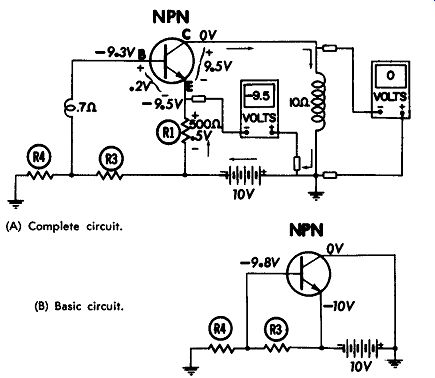
(A) Complete circuit. (B) Basic circuit.
Fig. 5-8. A positive-ground NPN circuit.
Emitter resistor R1 in Fig. 5-8A is 500 ohms and there is 0.5 volt across it. Since the electrons are flowing up through R1, the voltage across R1 will be negative at the lower end and positive at the top. In other words, this voltage opposes the battery voltage, so it subtracts from the latter, leaving only -9.5 volts between emitter and ground.
The base voltage is set by voltage divider R3-R4, so it is about 0.2 volt positive with respect to the emitter. This makes the base voltage -9.3 volts with respect to ground.
The important thing to note in Fig. 5-8 is that the voltages, if measured between elements, are the same as they were in the negative ground system. In other words, the rules that applied in Fig. 5-7 still hold true: When the negative voltmeter lead is placed on the emitter, all voltages will read positive.
The base voltage will read about 0.2 volt (for a germanium transistor), compared to that of the emitter, and the collector voltage will be 9.5 volts. Thus, the fact that a positive ground is used will not change circuit operation nor the voltages when read with respect to the emitter.
Actual Radio Voltages
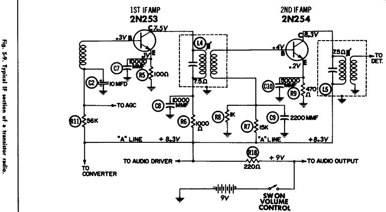
Fig. 5-9
All the principles we have learned so far about voltages in NPN circuits will now be applied to an actual radio schematic.
The 1st and 2nd IF stages of a typical transistor portable using NPN transistors is shown in Fig. 5-9. A 9-volt battery with negative ground is used. The full battery voltage is applied to the audio-output stage, but the voltage to the other stages is dropped to 8.3 volts by a 220-ohm resistor, R18 in the "A" line.
The 2N253 transistor has a 100-ohm resistor, R5, in its emitter lead; 0.1 volt is produced across this resistor by the collector current. The collector of the 2N253 is connected to a 7.5-ohm IF transformer winding, which produces no noticeable voltage drop. However, there is also a 1,000-ohm resistor (R6) in series with the collector lead, and 0.8 volt is dropped across it, leaving 7.5 volts on the collector. It is important to note that sufficient resistance values and collector current flow produce voltage drops across the emitter and collector resistors.
The 2N254 transistor (2nd IF) in Fig. 5-9 has more resistance in the emitter circuit, but less in the collector lead. Emitter resistor R9 is 470 ohms, and 0.2 volt is developed across it by the flow of collector current. The collector lead has no resistance except the 7 .5-ohm IF coil, so essentially the full 8.3 volts from the "A" line reach the collector. The base voltage is set by a voltage divider, R7-R8, in the usual manner. The base voltage of the 2N253 (1st IF) transistor is varied slightly by the AGC voltage, which in turn varies the collector current of that stage. This will change all voltages if the radio is tuned to a strong station; thus, voltages should always be measured with the radio tuned "off station." If this is done, the AGC system need not be disabled.
The 2N253 transistor in Fig. 5-9 is drawing about one milliampere, and the 2N254 transistor is drawing slightly less than half this much.
PNP TRANSISTORS
The basic PNP circuit is shown in Fig. 5-10. The emitter voltage now becomes the most positive, because the battery has been turned around-the positive pole connected to the emitter and the negative pole to the collector.
If a vacuum tube were turned around so the electrons had to flow in the opposite direction from normal, the battery would have to be turned around also. In other words, for the electrons to be pumped counterclockwise, around the circuit, the battery must be connected as shown in Fig. 5-10. Since PNP transistors are designed to pass electrons from collector to emitter, the battery must be connected to send electrons into the collector, through the transistor, and then out of the emitter as shown by the arrows. This is why, in PNP transistor circuits, the emitter is usually connected to the most positive voltage.
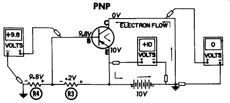
Fig. 5-10. The basic PNP transistor circuit.
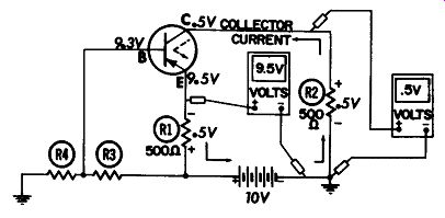
Fig. 5-11. Voltage distribution in the PNP transistor circuit.
If there are no resistances in the emitter and collector circuits, the full battery voltage will be found across the transistor, from emitter to collector. The base voltage is usually maintained by a voltage divider, R3-R4, at a slightly less positive voltage than that of the emitter.
Effect of Emitter and Collector Resistors
In Fig. 5-11, the same circuit is shown, except emitter and collector resistors have been added. The flow of electrons through these resistors causes voltage drops of the polarities shown.
Now, when the collector voltage is measured with respect to ground, the meter is actually being placed across collector resistor R2. This means that if the transistor is conducting, a voltage will be read at the collector; but if not, the collector voltage will read zero because R2 does not have a voltage drop across it.
The emitter reads 9.5 volts because the same current also makes a circular path and passes through emitter resistor R1.
The voltage drop across R1 is subtracted from the battery voltage, leaving 9.5 volts at the emitter. A base current will also pass through R1, but it is usually so small it does not add significantly to the voltage drop across the resistor.
The voltage drops across R1, R2, and the transistor add up to the battery voltage. This follows the rule for series circuits (0.5 volt plus 0.5 volt plus 9 volts = 10 volts).
Effect of Coupling Transformers
As with NPN transistors, transformers often do not cause a readable voltage drop. This is especially true of IF trans formers, where the resistance and the collector current are rather small.
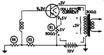
Fig. 5-12. A noticeable voltage drop occurs when there is an audio transformer
in the collector circuit.
Audio transformers often do produce a noticeable voltage drop. The collector transformer winding in Fig. 5-12 has a DC resistance of 300 ohms; a current of only 1 milliampere would cause the collector voltage to rise to 0.3 volt. The same current, as it passes through emitter resistor R1, causes a little larger voltage drop there because R1 has a little more resistance than the collector winding. The fact that the emitter voltage is not 10 volts and the collector voltage is not zero indicates the transistor is conducting in that circuit.
Base voltage is not affected by the transformer winding in the base lead because that winding usually has such a low resistance and base current is so small that no significant voltage is dropped there.
Estimating Collector Current
Usually the troubleshooter only wants to know whether or not the transistor is conducting-the exact amount of current is not too important. In some audio amplifiers, however, the value of the collector current is important, and a potentiometer may even be provided in the base circuit so the current can be adjusted.
The current in Fig. 5-12 can be figured from Ohm's law, by dividing the voltage drop across a resistance by the value of that resistance. We know the voltage across the collector transformer is 0.3 volt and the resistance is 300 ohms, so collector current must be 1 milliampere.
Collector current is sometimes adjusted by using the collector voltage as an indication. When the voltage is right, the current will also be about right. This makes it unnecessary to break any leads to measure current. In those circuits where the collector current is adjustable, R4 will usually be a vari able instead of a fixed resistor.
Voltages Between Elements
The voltage the transistor sees is the one between its elements, and this is what it operates on.
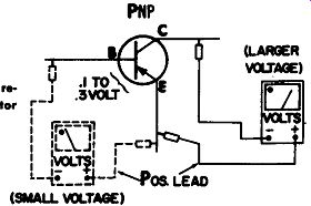
Fig. 5-13. Voltages measured with respect to emitter In a PNP transistor
circuit.
Most PNP transistors will have the most positive voltage applied to the emitter; therefore, when the emitter is used as a reference, the base and collector will be negative. This means that if the positive meter lead is placed on the emitter and the negative lead is used as a probe, as shown in Fig. 5-13, the voltages will usually read up the scale. Exceptions are some times found in certain converter, detector, and push-pull output stages, where the base-to-emitter voltage may be zero or even reversed in polarity. In converter circuits, the oscillator signal may reverse the bias, but this is normal if the voltages are listed that way on the schematic.
PNP Circuit with Positive Ground
As with NPN circuits, a positive ground may be used on some sets. When checked with respect to ground, all voltages will then be negative.
In Fig. 5-14, the emitter is the least negative because it is nearest to ground. The only reason any voltage is read on the emitter is that there is a voltage drop across emitter resistor R1; otherwise, the emitter voltage would be zero.
Collector voltage reads -10 volts because it is almost directly connected to the negative pole of the battery ( collector transformer resistance is quite low). Voltage divider R3-R4 keeps the base slightly more negative than the emitter. The important point is that the transistor elements still see the same voltage polarities with respect to the emitter.
Actual Radio Voltages
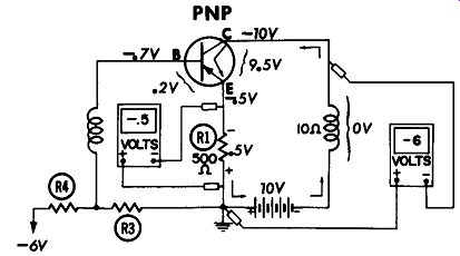
Fig. 5-14. A typical positive-ground PNP circuit.
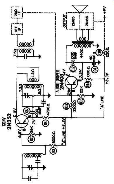
Fig. 5-15. Normal voltage distribution in typical PNP converter and driver
stages.
In Fig. 5-15 the 2N252 converter has a 4,700-ohm resistor, R4, in the lead between the emitter and the 8.3-volt "A" line.
Collector current flowing through the resistor causes a drop of 1.3 volts across R4, leaving 7 volts on the emitter. If the 2N252 transistor were not conducting, no voltage would be dropped across R4 and the emitter reading would be considerably higher.
Voltage divider R2-R3 keeps the base voltage about 0.2 volt less positive than the emitter, as is customary for most PNP circuits. As mentioned previously, however, some PNP converter circuits operate with the bias reversed-that is, the base may appear to be more positive than the emitter as long as the oscillator is oscillating. If the schematic calls for a re versed bias between base and emitter, that is one way to tell if the oscillator is oscillating. The only reason for a bias reversal in this type of circuit is that the oscillator signal is sometimes strong enough to reduce the emitter voltage below normal. If the oscillations are stopped, the bias will return to a normal forward bias. The oscillator tank circuit sends its signal voltage to the emitter through a 1,000-mmf capacitor, C6, where the signal is detected by the emitter diode. In Fig. 5-15, however, the oscillator does not cause a bias reversal.
The collector circuit contains two transformer windings-the 1.2-ohm oscillator feedback winding and the 7.5-ohm IF primary. Neither coil has sufficient resistance to cause any noticeable voltage drop, so the collector voltage reads zero.
Fig. 5-15 also shows the audio driver stage, which employs a 2N403 transistor. The collector has an audio transformer winding with a DC resistance of 440 ohms; thus, a voltage drop of 0.4 volt is produced as the collector current passes through that winding. This causes the collector voltage to read 0.4 volt positive with respect to ground.
The emitter of the driver transistor is tied to the 8.3-volt "A" line through R14, and 7.5 volts are measured at the emitter.
Base resistors R12 and R13 keep the base slightly negative with respect to the emitter.
SUMMARY
Schematics show normal voltage readings between each transistor element and ground but these are not the most important voltages in a transistor radio. Although it is important to understand what produces those voltages, the readings which mean the most in troubleshooting are:
1. The battery voltage under load (radio on).
2. The voltage across the emitter resistor, which tells if the transistor is conducting or drawing current. (In some circuits, this voltage may be measured across the collector resistor or coil.)
3. The bias, or voltage between base and emitter, which "tells" the transistor to conduct by pulling current carriers out of the emitter.
These three voltage checks (Fig. 5-16) are the first ones made when searching for trouble in a stage. After we learn all we can from those checks, voltages to ground may be read, but they are made only to confirm what we already suspect the trouble to be.
The reason the "conduction test" is so important is that it tells so much about the condition of the stage. By this one simple test we can learn if anything is open in the collector current path--resistors, coils, leads, or the transistor itself. It even tells us more than that, for if any of the leads, resistors, or coils in the base circuit are open, the bias would not be normal. And the collector current will be upset. So, by this one check we can tell about the condition of all components which pass DC, whether they be in the collector circuit, the base circuit, or the transistor itself. This saves much time over what it would take to check all of those components individually.
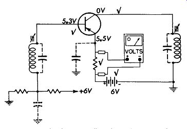
Fig. 5-16. Normal voltages usually indicate that DC conducting components
are okay.
If conduction is normal and the stage still won't pass a signal properly, a capacitor may be open or a coil detuned. But, by making the voltage checks, we at least know where to look for the trouble. This system, along with the method of isolating the trouble to one section of the radio saves an incalculable amount of time. Systematic troubleshooting makes a lot more sense (and cents!) than the old "hunt and poke" technique ever did.
The next question is, "What happens to the conduction, bias, and other voltages when certain components open or short?" How can we tell which component is defective by making these measurements? The next section is designed to give you a feel for this. It will probably be the greatest aid in diagnosing troubles we could possibly give you.