AMAZON multi-meters discounts AMAZON oscilloscope discounts
Now that you are familiar with AM transistor radios and how signals pass through them, it is a simple matter to "chart the same course" in radios in which the FM provision has been added.
The basic circuits are almost the same-and the same principles apply. That is, transistors are used as amplifier or oscillator stages, and the circuits look very much like AM circuits in most cases. The DC circuits are set up in much the same manner, with a stabilizing resistor in the emitter, a voltage divider in the base to obtain "bias," and the collector returned to battery negative (NPN) or positive (PNP) . The main difference is that some of the tuned circuits which couple signals in and out of each stage are wound with fewer turns to handle the higher frequencies.
In most AM-FM radios, the same audio system, except for the detector, is used for AM and FM. Since the purpose of the AM audio amplifiers is to amplify changes in amplitude (audio signals), and the purpose of the FM detector is to change frequency variations into amplitude variations (audio signals), the same audio amplifiers can be used. The amplifiers are simply switched to receive the output of the AM detector when listening to AM, or the FM detector when tuned to FM. Both detectors produce small, audio signals which need amplification before they can drive a speaker.
As with AM signals, the FM signals must be amplified before they can be detected. Most of the signal in any radio system is lost while traveling between the station and the receiver. This is especially true with FM because the signals are transmitted at higher frequencies (88 mhz-108 mhz) which are not reflected back to earth by the ionosphere. Only the direct (line of sight) signals are received. Any obstacles such as buildings or hills between the transmitter and the FM radio will tend to block the signal.
The section of the radio which builds up the FM signals received at the antenna is called the "FM Tuner." It employs one or more transistors which work at higher frequencies than AM transistors but are similar otherwise. The FM converter (oscillator) and IF amplifiers also must operate at higher frequencies.
As with the AM radio, after checking the batteries and looking the set over thoroughly for visible defects, the next step is to get out the schematic and become familiar with the general layout of the set. This only takes a few seconds and will save time in the long run.
SCHEMATIC FAMILIARIZATION
The schematic in Fig. 4-1 represents a typical AM-FM radio less the audio system. In this section, we will get you familiar enough with AM-FM radios, so that a quick glance at a schematic will give you all the road map you need.
From this schematic, we learn that there are two stages in the "FM tuner section" of the radio (the FM-RF amplifier and the FM converter) . The tuner section is followed by the "IF strip," consisting of three stages. The three IF amplifiers are called dual purpose amplifiers, because they not only amplify the FM-IF signals, but they also amplify the AM signals.
Note that the 1st FM-IF stage doubles as the AM converter; the 2nd FM-IF serves as the 1st AM-IF, and the 3rd FM-IF serves as the 2nd AM-IF amplifier. The way that this is accomplished will be described later. The combining of the AM and FM-IF strips is quite common, since it saves transistors and other parts. Only the more expensive units have a separate converter and IF amplifier section for AM. After IF amplification, the AM signals are detected by the AM audio detector (Fig. 4-2) , and the FM signals are detected by the FM detector. They are then fed into the common audio system.
The individual stages and their functions are:
1. FM RF Amp.
2. FM Converter
3. 1st FM-IF AM Converter
Amplifies the FM signals.
Changes the incoming FM signals (88 mhz-108 mhz) to an IF signal (10.7 mhz). Amplifies the 10.7 -mhz FM signal.
Changes the AM-RF signals to IF signals ( 455 khz) .
4. 2nd FM-IF 1st AM-IF
5. 3rd FM-IF 2nd AM-IF
6. FM detector AM detector
7. Audio Amp.
8. Audio Amp. (driver)
9. Audio output Amplifies the 10.7-mhz FM signal.
Amplifies the 455- khz AM signal.
Further amplifies the 10.7 -mhz signal.
Further amplifies the 455- khz signal.
Changes the FM signal to audio.
Separates the audio from the 455 khz signal.
Amplifies the audio.
Further amplifies the audio.
Builds up sufficient audio power to drive the speaker.

Fig. 4-1
The block diagram (Fig. 4-2) shows the path the FM signal takes in dotted lines, and the AM signal flow in solid lines.
Note that the AM portion of the radio is identical to the lay out previously studied in Section 3. The only differences are:
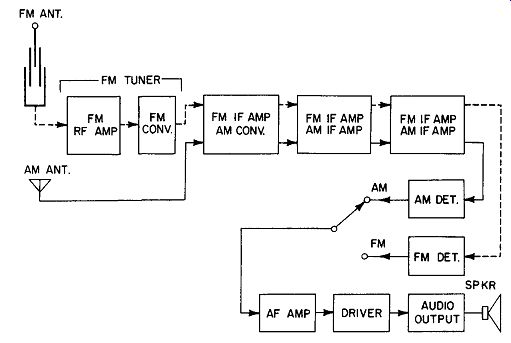
Fig. 4-2. Block diagram of the AM-FM receiver in Fig. 4-1.
1. A two stage FM tuner has been added.
2. An FM detector has been added.
3. Transformers tuned to 10. 7 mhz have been added in the IF stages to allow those stages to pass the FM-IF signal.
Circuit Description and Test Points
The circuits in Fig. 4-1 are almost identical to those in the AM receiver previously studied. In this case, all transistors happen to be PNP type, but many AM-FM receivers use NPN transistors in some stages.
As previously stated the emitter lead (in PNP circuits) goes through a stabilizing resistor to the positive side of the battery and the collector goes to the negative pole through some sort of "load." This holds true in every stage of this receiver. Also, the base lead of each transistor is connected to a voltage divider for its bias. For example, in the FM-RF amplifier stage, R1 and R2 form the voltage divider. R3 is the emitter stabilizing resistor and L2 is the collector load. In other words, the very same DC circuit conditions are set up here as we had in the basic amplifiers studied previously. This is important to re member when we start to troubleshoot this receiver.
But what about the AC circuits? By that, we mean the path that the broadcast signals (which are actually AC voltages) take as they pass through each stage. In the circuits studied in previous sections, we found that the signal was injected, or inserted, in series with the base lead of each stage. That voltage is then either added to, or subtracted from, the DC bias voltage, depending on which half cycle it was on. This is where the first two stages of our AM-FM receiver differ.
FM Tuner
FM signals enter the RF stage through antenna coil L1 and coupling capacitor C1. Note that they are coupled to the emitter, not to base. The base is bypassed by capacitor C2, which holds it at ground potential and keeps it from varying with the signal. The signal is developed across R3; thus it is in series with the emitter lead instead of the base. This type of circuit--known as a common (or grounded) base circuit--has certain advantages in the FM tuner stages; it allows the transistors to operate efficiently at higher frequencies and provides better voltage gain. When the signal is coupled into the base, we call it a common ( or grounded) emitter circuit. The latter is more popular for most applications, because it gives greater power gain.
When troubleshooting and injecting test signals into a stage, it is very important to first check the schematic to see where the signal is coupled in. If we pick the wrong point, it would appear that the stage is dead, because the test signal would be bypassed to ground. This would happen if we used the base of the FM-RF amplifier; we should inject the signal into the emitter where the regular FM signal enters (Fig. 4-1). The FM converter is very similar to the AM converter discussed previously (See Fig. 3-1), except that the FM signal is coupled into the emitter along with the oscillator signal from L3. Oscillator coil L3 and its associated capacitor C3 are tuned to a frequency which is 10.7 mhz above the frequency of the FM station being received (Fig. 4-3).
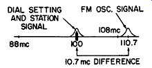
Fig. 4-3. The oscillator oscillates 10.7 mhz above the incoming station
frequency.
Dual-Purpose IF Stages
If two tuned circuits which are resonant at greatly different frequencies are connected in series and the same signal is fed to both of them, the signal will only "see" the circuit to which it is tuned. This is called electronic switching; it is accomplished automatically and no switches are needed in each stage.
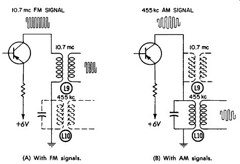
Fig. 4-4. How the IF tuned circuits look to incoming signals. (A) With FM signals.
(B) With AM signals.
Fig. 4-4A shows the collector circuit of one of the FM-IF stages. Note that the 10.7 -mhz IF transformer and the 455- khz IF transformer are in series. When the radio is tuned to an FM station and the 10.7 mhz signal is produced (in the FM converter), L9 appears as a high resistance to the signal and literally "captures" it. It is then sent to the next stage. Trans former L10, however, looks like a complete "short" to the signal, since it is tuned so far off the signal frequency. L10 acts just like a piece of wire conductor (as shown in Fig. 4-4A). Another way of looking at it is that the capacitor across L10 bypasses the signal around the coil, since the 10.7 mhz signal can pass through the capacitor very easily.
Now what happens when the radio is tuned to the broadcast band and AM stations are being received? The AM converter stage produces a 455- khz IF signal as shown in Fig. 4-4B. As the signal passes through the IF stages for amplification, it "sees" only the 455- khz transformer L10. Why? Because L10 acts like a high resistance, while L9 is so far off frequency it acts like a piece of wire. Actually, L9 is only a few turns of wire; there fore, it has a small inductance and doesn't react to the relatively low 455- khz frequency.
Thus, whichever type of signal being received is passed on to the next stage after amplification by the transistor. After passing through all IF stages, the signals are fed to one of the detector stages for conversion to audio.
AM and FM Detection
Conversion from an amplitude modulated 455- khz signal to audio is simple and is accomplished in the same manner as it is in a straight AM receiver. A diode (X3 in Fig. 4-5) removes one half of the envelope, and filters C33, C34, and R33 remove the 455- khz frequency. This leaves pure audio, which is then amplified by the audio system.
FM is different. Frequency shifts are present instead of amplitude variations. The FM detector must convert these frequency changes to amplitude changes, or audio. Note that L11 in Fig. 4-5 is tuned to 10.7 me. Assume that a signal of exactly 10. 7 mhz is fed to L11 (by a signal generator or unmodulated FM station). The induced voltage in winding Z assists the voltage in windings X and Y equally, causing diodes X1 and X2 to conduct equal amounts of current (see arrows). This causes two currents of equal magnitude to flow through load resistor R1 in opposite directions, so no output voltage is developed across R1.
As the frequency shifts above 10.7 mhz ( due to modulation), a phase shift takes place, causing winding Z to assist winding X more than it does winding Y. Diode D1 now conducts more than diode D2, causing a positive voltage to be produced across R1. When the frequency shifts below 10.7 mhz, winding Z assists winding Y the most, causing X2 to conduct heavier than X1. This causes a negative voltage to be developed across R1.
Since R2 actually represents the volume control, the pulsating voltage is fed to the audio amplifiers. The voltage coupled via C1 and S1 to R2 is pulsating at the audio rate (in step with the shifts in frequency) and an audio signal is heard.
Balancing the FM Detector
In order for the detector to work properly, it must be balanced to make sure that 0 volts is obtained when exactly 10.7 mhz is fed into the radio. Although a 10.7 -mhz IF signal can be obtained when a station signal is tuned in perfectly ( assuming that the rest of the radio is aligned properly) there are too many variables for this to be accurate. It is best to feed in a 10.7-mhz signal from a crystal-controlled signal generator.
Balancing is then accomplished by adjusting the slug for Coil X ( detector transformer L11 secondary) for 0 volts on a meter connected between points A and B (Fig. 4-5) . This pre vents audio distortion by assuring a balanced plus and minus voltage during station modulation.
Fig. 4-5. Simplified schematic of detector and audio stages.
ISOLATING TROUBLES
When troubleshooting an AM-FM radio, approach it as you would a straight AM radio, by:
1. Checking batteries and battery current.
2. Looking the radio over carefully for obvious defects (batteries in backwards, cracks in circuit board due to drop ping the radio, etc.) .
3. Sectionalizing the radio, or getting an idea as to what section the trouble is in.
4. Reading voltages to pinpoint the exact trouble spot.
Since Step 4 will be covered in detail later the remainder of this section will be devoted to Step 3.
Listening Test
Usually by just listening to the AM-FM radio, you can tell what area the trouble is in. This is true because there are certain stages of the radio which function only when tuned to FM, and some which function only when tuned to AM. Other stages function during both AM and FM reception.
Once you have glanced at the schematic, think of it in terms of a block diagram (Fig. 4-6). When the switch is in the FM position, the FM tuner is in the circuit; during AM, it is not functioning. The IF section functions on both bands, except each tuned circuit is sensitive to only one frequency. Each detector functions on its own band only, and the audio system serves both bands.
Let's assume that the radio is dead on FM but works fine on AM. The trouble is probably in the FM-tuner section or in the FM detector. If the radio is dead on AM but performs all right on FM, the AM detector or the oscillator portion of the AM converter stage may be out (some radios have a separate AM oscillator transistor).
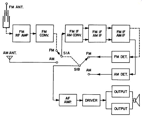
Fig. 4-6. Keeping the general layout in mind.
If the radio is dead on both AM and FM, the trouble is probably in one of the stages which functions for both-the IF or audio section. A weak radio may be due to a defective or detuned antenna, tuner, or IF transformer. (See Table 4-1.)
--------------
TABLE 4-1.
Probable Causes of Defects in AM-FM Receivers
Indication Probable Trouble Area
FM Dead; AM OK FM Tuner or FM Detector AM Dead; FM OK AM Detector or Oscillator AM and FM Dead IF or Audio Section FM Weak; AM OK FM Antenna, Tuner, or IF-Tuned Circuit AM Weak; FM OK AM Antenna or Alignment FM Distorted; AM OK FM Detector, Detector Transformer, or Alignment
--------------
Signal Injection
Signal injection can be used, as it was on straight AM receivers; however, there are some differences which will be noted.
Since noise is amplitude modulation (AM), noise generators will not work on FM. This is also true for "click" or shock tests.
Many technicians, however, use noise generators with the radio in the AM position; this checks all the dual-purpose stages and the AM detector.
Starting at the volume control, we can inject noise to see if the audio stages are working. A noise generator can be used for this test, but the radio probably has its own noise generator located at that point-the volume control itself. After some use, the control usually gets a little noisy. This noise is amplified by all of the audio stages if they are working. Put your ear next to the speaker and turn the control back and forth near the high-volume setting. If a little noise is heard, the audio amplifiers are probably working.
If the audio stages are working, place a noise generator on the base of the first AM-IF transistor. This checks the AM-IF amplifiers and the AM detector. Next move to the AM converter or antenna. A loss of signal at any point indicates trouble. When this occurs, certain voltages, described in the following section, should be read.
AM-FM radios have another "built-in" noise generator which operates when the radio is switched to FM. The FM tuner produces a high-pitched hissing sound when the volume control is turned up and the radio is tuned between stations. This hiss is due to the increased noise level inherent in most high frequency transistors. Before this hiss is heard, however, all of the FM-IF amplifiers must be working. Usually the FM converter must also be working because very little hiss is produced by the IF amplifiers.
If the FM-IF amplifiers and the FM converter are working, there will usually be a mild hiss with volume control turned all the way up. If the FM-IF amplifiers, FM converter, and FM-RF stages are all working, a louder hiss level will be heard. A loud hiss level but no audio usually points to a bad FM-antenna or FM-oscillator circuit.
Using a Signal Generator
Signal generators are seldom used on AM-FM radios; the trouble can usually be sectionalized by merely listening to the radio ( on both AM and FM) , by a noise generator ( on AM), or by tuner noise (FM). FM signal generators, however, are often used for alignment of AM-FM auto radios. They re quire very precise alignment because it is difficult to obtain passable FM performance in a moving vehicle. This will be discussed in a later section.
Summary
Understanding how the AM-FM radio works and visualizing a block diagram as you glance at the schematic saves considerable time in localizing troubles. After checking batteries and listening to the radio-on both AM and FM-a pretty good idea of the trouble area can be determined. Four types of signals are available without even turning on a signal generator. They are:
1. Volume control "scratch" which can usually be heard with ear next to speaker as control is rotated. Checks: Audio amplifiers.
2. AM station signals. Checks: AM converter, IF amplifiers, and AM detector.
3. FM station signals. Checks: FM tuner, IF amplifiers, and FM detector.
4. FM tuner hiss.
Checks: Normal hiss with no FM signal points to FM oscillator or antenna circuit trouble. Weaker hiss with no FM signal points to FM-RF stage trouble.
In other words, we can automatically inject signals at the following points in the radio by simply utilizing what is already available to us: at the audio input (by rotating volume control); at the AM converter (by switching to AM stations); at the FM-IF (by switching to FM tuner hiss between stations); at the FM-RF (by tuning in FM stations).