AMAZON multi-meters discounts AMAZON oscilloscope discounts
Basic Theory
It is evident everywhere in the engineering world that scientific progress depends on the ability to make accurate measurements.
Reciprocally, it is always an essential task of engineering to design more accurate measuring devices to assure further progress. This interrelationship has resulted in the accumulation of an enormous body of exact knowledge through constantly improved observations and measurements.
In contrast to the measuring devices of 150 years ago, some present-day instruments are amazingly accurate. But this degree of perfection did not arise suddenly. It is worth noting that many of the present instruments evolved through a process of continual refinement. Remarkable progress has been made, especially in the field of electrical measurements.
This Section briefly contrasts two fundamental methods of measurement and introduces the bridge.
1.1 TWO BASIC TYPES OF MEASUREMENT
All measurements may be said to fall into two categories : those which make indirect use of a standard, and those which make direct use of a standard. Measurements of the "indirect" type enjoy great popularity because of their speed, simplicity, and convenience, but those of the "direct" type offer the better accuracy. It should be noted that the words direct and indirect refer here to the relationship of the test instrument to the standard, not to the method of taking readings. An "indirect" instrument-yardstick, simple thermometer, or simple voltmeter-usually gives direct readings.
Instruments which use the indirect approach are calibrated from a standard; e.g., a voltmeter is connected to a precision voltage source, the corresponding deflection noted, and the meter adjusted, if necessary, for agreement between the standard voltage and the indicated voltage. Thereafter, the instrument is used by itself, and it is returned to the standard, if ever, only when the calibration is rechecked. Instruments which use the direct approach, on the contrary, are always used in conjunction with the standard. This provides a continual comparison of measured values to standard values, and is the chief reason why the direct method is the more accurate.
1.2 INDIRECT METHOD: ADVANTAGES and DISADVANTAGES
Most instruments using the indirect method give direct readings ; i.e., the "unknown" values are read immediately from the position of some indicator on a graduated scale. Examples are thermometers, simple weighing scales, clocks, and electric meters.
Advantages of such instruments and of the indirect method are simplicity (because the readings are easily taken) and speed. Speed is achieved because operation is almost instantaneous and usually requires no manipulation other than setting a range control; an operator, for example, need only set a voltmeter to the correct range, connect the meter to the circuit or device under test, and read the voltage from the meter scale. Additionally, a costly standard is not needed.
Disadvantages of the indirect method are those inherent in most direct-reading indicators used away from a standard: (1) a multistage process is employed and performance in any one, or all, of the stages can deteriorate after calibration; thus, in a voltmeter the voltage under test sends a proportional current through the pivoted coil of the instrument in series with a suitable multiplier resistor, and this current, in turn, sets up a magnetic field which causes the coil to rotate and move the pointer over the scale; (2) since the instrument is divorced from the standard, there is no way of knowing, between calibrations, whether the indications are correct; (3) error can result from reading the indication and may be caused by parallax, misinterpretation of the value denoted by a scale division, or lack of skill in estimating the position of an indicator when it stands between divisions;· (4) indirect electrical measurements usually draw current from the circuit being measured and so cause loading effects which may seriously impair accuracy.
1.3 DIRECT METHOD: ADVANTAGES AND DISADVANTAGES
Instruments employing the direct method are always used in conjunction with a primary or secondary standard. In some instances, they are operated near a stationary, external standard; in others, the standard is contained in the instrument itself. In some instances, the standard is used intermittently, and in others, continuously. Examples of "direct" instruments are self-calibrating voltmeters, and frequency meters with standard frequency oscillators.
A simplified illustration of a dc voltmeter with self-contained standard is given in Fig. 1-1. In this circuit, voltmeter M is normally connected to test terminals X-X through push-button switch S1 (normally closed against contact 1) and can indicate an external voltage applied to the test terminals. E8 is an accurately known voltage supplied by a built-in battery or standard cell. When S1 is depressed so as to close temporarily against contact 2, external voltage Ex is removed and standard voltage EM is applied to the meter. In this way, the calibration of the meter scale may be checked at will against the standard voltage, EM' Best accuracy results when Ex = EM, Le., when the deflection is the same for both voltages. But this condition is obtained only occasionally, e.g., when an external voltage must be adjusted to the standard value.
The advantage of the direct method is the accuracy due to correlation with the standard. Disadvantages are : (1) it is slower than the indirect method; (2) it requires somewhat bulkier instrumentation; and (3) its greater accuracy results when the unknown voltage equals the standard voltage, which means that number of standard voltages (or one accurately adjustable standard) will be needed for most accurate measurement of a range of voltages.

Fig. 1-1. Voltmeter with internal standard.
1.4 THE NULL METHOD
A special version of the direct method keeps the standard in continuous use during a measurement, thus differing from the method described in Section 1.3 in which the standard is engaged only intermittently.
Fig. 1-2 shows a simplified example of this version. Here, M is a center-zero d-c voltmeter or galvanometer. E8 is an accurately known standard voltage, and Ex an unknown voltage to be measured. When Ex = E8, the two voltages cancel each other and the meter reads zero.
When Ex is higher than Ea, terminal b of the meter is more positive than terminal a, so electrons flow in the direction of the dotted arrows and deflect the meter upscale (positive) . When, instead, Ex is lower than E8, terminal a is more positive than terminal b, the current reverses to the direction of the solid arrows, and the meter is deflected downscale (negative).
(A) Circuit. (b) Response.
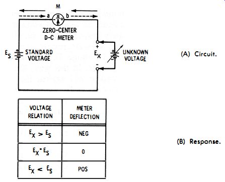
Fig. 1-2. Demonstration of null method.
The condition of zero deflection, indicating equality of the two voltages, is termed null. Since at null the standard and unknown voltages are balanced, the circuit is said to be balanced when it is adjusted to null. In this respect, the arrangement is the electrical analogy of the. type of balance in which accurate weights are placed in one pan, and enough material is placed in the other pan to balance the known weight, as indicated by the zero reading of the indicator. Accuracy is increased because, at balance, no current is drawn from the source, E_x.
When E_x and E_s differ greatly, the full-scale range of meter M must be high enough to accommodate the net voltage without damage. As null is approached, however, the meter sensitivity may be increased, with an accompanying large increase in accuracy of the null setting.
When Ex is very close to Ea, the lowest range of the meter may be used. Thus, various shunts may be switched across a galvanometer to control its sensitivity.
The null method has several advantages : (1) the standard is continuously referred to; (2) the meter scale needs no special calibration, since no absolute values are read from it ; (3) null, the condition of final adjustment, is read as zero deflection-a point which can be easily recognized; (4 ) accuracy is improved by the absence of "loading" on the source, Ex, at null. Thus, Ex is referred directly to the standard (Es), and the various links which can introduce error in the indirect method are avoided.
1.5 NULL CIRCUIT WITH VOLTAGE DIVIDERS
One or both of the batteries in the previous circuit (Fig. 1-2) may be combined with a continuously variable voltage divider to make the voltage adjustable. Fig. 1-3 shows a two-divider arrangement . Here, voltage divider R 1 supplies a selected fraction (e1) of voltage Es, while R2 similarly supplies a selected fraction (e2) of voltage Ex.
As in the preceding example, both e1 and e2 are positive ; therefore, the meter deflects downscale when e1 is more positive than e2, upscale when e1 is less positive than e2, and reads zero when e1 = e2.
A disadvantage of this design is that both Es and Ex are constantly under load and therefore may not be able to put out their true open circuit voltages. For both Es and Ex, this is not a true null method.
UPSCALE
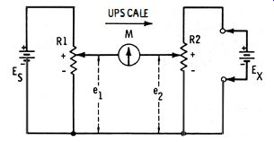
Fig. 1-3. Null circuit with voltage dividers.
1.6 BASIC DC BRIDGE: CONFIGURATION
The dual voltage-divider circuit shown in Fig. 1-3 can be used to compare resistances as well as voltages. Thus, in Fig. 1-4A, batteries E1 and E2, which are exactly equal in voltage, force currents 11 and 12, respectively, through voltage dividers R1 and R2. The resultant voltage drops e1 (= 11rd, e2 (= 11r2) , ea (= 12ra) , and e4 (= 12r4) are proportional to resistances r1, r2, ra, and r4 , respectively. At null, e1/e2 = ea/e4, so rt/r2 = ra/r4 . And from this relationship, any one of the resistances may be determined in terms of the other three: r1 = (r2ra) /r4, r2 = (r1r4) Ira, ra = (r1r4) /r2, and r4 = (r2ra) /r1' In this way, one unknown resistance may be determined from the values of three accurately known resistances.
Resistance determinations may be made without the two separate batteries ; the voltage dividers may be connected in parallel and operated from a single d-c source, as shown in Fig. 1-4B. Here, the current, voltage, and resistance relations are the same as in the pre-ceding example. With Fig. 1-4B, the basic configuration of the bridge emerges.
(A) Two-battery circuit. (B) Single-battery circuit. (C) Conventional representation.
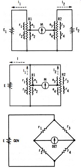
Fig. 1-4. Evolution of bridge.
Fig. 1-5. Basic a-c bridge config.
Usually, a bridge circuit is drawn in the 'diamond shape shown in Fig. 1-4C. Here, rh r2, ra, and r4 are separate arms of the bridge and correspond to the selected resistances r1 and r2 of potentiometer R1, and to ra and r. of potentiometer R2 in Fig. 1-4A. One arm, such as rl> may be made continuously variable for balancing the circuit to null, and one (such as r2 ) may be the unknown. The two remaining arms, ra and r4, then are accurate resistances whose ratio determines the ratio of the unknown (r2 ) to the standard (r 1)' Thus, at null the unknown r2 = (r./r3)r1. In bridge parlance, the power source (such as the battery in Fig. 1-4C) is termed the generator, and the null indicator (such as the center-zero galvanometer in Fig. 1-4C) is the detector.
The basic bridge circuit was invented by S. H. Christie, an Englishman, who described it in a paper in the February 28, 1833, issue of Philosophical Transactions. But the device attracted little attention until 1843, when it was publicized by Sir Charles Wheatstone, from whom it came to be called the Wheatstone bridge despite Sir Charles's painstaking credit to Christie.
The bridge enables an unknown quantity to be checked directly against a standard which is permanently contained in the circuit.
Bridges are used for accurate measurement of such properties as resistance, capacitance, inductance, impedance, and frequency.
1.7 BASIC A-C BRIDGE: CONFIGURATION
As a test instrument, a d-c bridge can be used only for the measurement of resistance. Capacitance, inductance, and impedance measurements, however, require that the bridge be powered by alternating current.
Fig. 1-5 shows the basic configuration of an a-c bridge. Note that the circuit is essentially like the d-c bridge, except that an a-c generator (GEN) has replaced the battery, and an a-c null detector (DET) has replaced the center-zero d-c galvanometer. The a-c detector may be a vacuum-tube (or transistorized) voltmeter, oscilloscope, magic eye tube, or headphones (with or without an amplifier) . Also, the resistance arms of the d-c bridge have been replaced with corresponding impedance arms Zt, Z2, Za, and Z4. (These impedances are of the form R + jX.) Calculations of unknown impedance in terms of standard impedance and ratio arms may be made in the same way described previously for resistance, simply by substituting z's for r's in the formula.
At low (audio) frequencies, an a-c bridge also may be used to measure resistance in the manner described for the d-c bridge, with the same r formula being used.
1.8 BRIDGE GENERATOR AND DETECTOR REQUIREMENTS
For the most efficient bridge operation, the generator (whether a-c or d-c) must have good output-voltage regulation, and its maximum output voltage must be held low enough to prevent damage to the bridge arms. Moreover, if the generator is of the d-c type, its output must be free from ripple. If the generator is of the a-c type, its output should exhibit a constant frequency and low distortion.
The detector (whether a-c or d-c ) should have provision for adjusting the response, so that its sensitivity may be increased as null is approached, thereby increasing the closeness to which the bridge may be set. Closeness of setting is enhanced also by a very high detector input resistance (impedance ) with respect to that of the bridge arms.
To sharpen the null response of the bridge, the detector must be sharply tuned to the fundamental frequency if the generator output has significant harmonic content.
In a-c bridges, performance is improved by using an isolating transformer between the generator and bridge, and between the bridge and detector. For best performance, these transformers must be well shielded internally.
For a given combination of resistances or impedances in the arms, the sensitivity of a bridge may be increased by raising the generator voltage (bridge signal). However, there is a safe limit beyond which the bridge current becomes excessive and damages the arms. It is for this reason that moderate generator output often is preferred, and the detector sensitivity is increased proportionately, as through a-c or d-c amplification. But some amplifiers tend to become unstable and susceptible to stray pickup when operated at high sensitivity, so a compromise generally must be reached between generator voltage and detector sensitivity.
Maximum sensitivity with a given fixed-output generator and fixed sensitivity detector is obtained when in the bridge circuit
r1 = r2 = r3 = r4 = rg = rd
...in the d-c bridge, and when...
Z1 = Z2 = Z3 = Z4 = Zg = Zd ... in the a-c bridge.
(The symbol rg or Zg is the generator output resistance or impedance; rd or Zd is the detector input resistance or impedance.)
Also see: