AMAZON multi-meters discounts AMAZON oscilloscope discounts
Although bridges are used today to measure many different quantities, such as resistance, capacitance, inductance, and frequency, the original bridge was strictly a resistance-measuring device. At present, resistance measurement remains a major function of the bridge.
Modem resistance bridges as a group cover the range from 0.01 milliohm to 1000 tera-ohms-a spread of 1020 to 1; and, depending on make, model, and technique, their accuracy can be as close as 0.0001 percent of the indicated resistance value.
Described below are representative resistance bridges from the rudimentary slide-wire type to more complicated varieties.
2.1 BASIC SLIDE-WIRE BRIDGE
Fig. 2-1 shows the most rudimentary resistance bridge circuit. In this arrangement, the variable balancing resistor is a single strand of resistance wire (the slide wire) tautly stretched between points A and B (or wound around a form having a circular cross section) and provided with a sliding contact (the slider). The wire is of uniform cross section and purity, so its resistance is directly proportional to its length.
As the slider is moved along the wire, it divides the latter into two parts: dh the length from point A to the slider, which has a resistance of Rs; and d2, the length from point B to the slider, which has a resistance of R4. Thus, the resistance increases on one side of the moving slider and decreases on the other side.
The bridge is composed of unknown resistance R1 (connected to terminals X-X), standard resistance R2, and the two sections R5 and R4) of the slide-wire variable resistor. Battery B is the generator, and the center-zero d-c galvanometer, M, is the detector. The on-off switch, S2 permits disconnection of the battery when the bridge is idle. The pushbutton switch, S 1, allows the galvanometer to be cut into the circuit momentarily to check the state of balance, thus protecting the galvanometer from continuous exposure to excessive unbalance current.
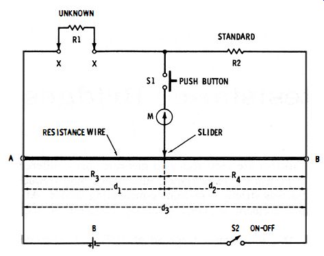
Fig. 2-1. Basic slide wire resistance bridge.
With the unknown resistance (R1) connected to terminals X-X, the bridge is balanced by moving the slider along the wire until zero deflection is shown on the galvanometer. At this null, R1/R2 = Ra/R., and from this relationship the unknown may be determined in terms of the standard:
R1 = R2(Rs/R.) 2-1
From this, it is clear that the slide wire provides the ratio arms of the circuit.
The total resistance of the slide wire is unimportant to the calculation. So also are the two resistance values on each side of the slider.
Distances d1 and d2 may be measured in inches or centimeters and used in the calculation in place of the actual resistances R3 and R4. Thus:

2-2
For this reason, the basic slide-wire bridge is convenient for emergency measurements of resistance, since it requires only a standard resistor and a length of bare resistance wire stretched along a meter stick or yardstick, in addition to a battery and d-c meter.
Sometimes it is more convenient to read the position of the slider with respect to the total length (d3) of the wire than to measure d1 and d2 separately. In such an instance :

2-3
It is apparent from either equation 2-2 or 2-3 that the unknown (R1) is equal to the standard (R2) when null occurs with the slider halfway between A and B (i.e., d1 = d2, and d1/d2 = 1) . Also, the slider must move to the right of center when R1 > R2, and to the left of center when R1 < R2. In practice, a meter stick or similar linear scale is usually mounted under the wire for reading d1 and d2 from the position of the slider.
If the wire is long (say, 1 meter ), little difficulty is experienced in measuring resistance over the range 0.01 R2 to 100 R2, provided a sensitive galvanometer is used. Unless the wire has reasonably high resistance, however, the current may heat it and impair the accuracy of measurement.

Fig. 2-2. Carey·Foster resistance bridge.
2.2 CAREY-FOSTER RESISTANCE BRIDGE
The Carey-Foster circuit (see Fig. 2-2) is a special version of the conventional slide-wire bridge. In this circuit, the slide wire is connected between the unknown (Rx) and the standard (Rs). The bridge is balanced in three steps : (l) Arms R1 and R2 are selected for an approximate null (i .e., R1/R2 == Rx/Rs). (2) The null is sharpened next by moving the slider over the length d1. (3) The resistor and a length of bare resistance wire stretched along a meter stick or yardstick, in addition to a battery and d-c meter.
Sometimes it is more convenient to read the position of the slider with respect to the total length (da) of the wire than to measure d1 and d2 separately. In such an instance: 2-3 It is apparent from either equation 2-2 or 2-3 that the unknown (R1) is equal to the standard (R2) when null occurs with the slider halfway between A and B (i.e., d1 = d2, and d1/d2 = 1) . Also, the slider must move to the right of center when R1 > R2, and to the left of center when R1 < R2. In practice, a meter stick or similar linear scale is usually mounted under the wire for reading d1 and d2 from the position of the slider.
If the wire is long (say, 1 meter ), little difficulty is experienced in measuring resistance over the range 0.01 R2 to 100 R2, provided a sensitive galvanometer is used. Unless the wire has reasonably high resistance, however, the current may heat it and impair the accuracy of measurement.
2.2 CAREY-FOSTER RESISTANCE BRIDGE
The Carey-Foster circuit (see Fig. 2-2) is a special version of the conventional slide-wire bridge. In this circuit, the slide wire is connected between the unknown (Rx) and the standard (Rs). The bridge is balanced in three steps :
(1) Arms R1 and R2 are selected for an approximate null (i .e., R1/R2 == Rx/Rs).
(2) The null is sharpened next by moving the slider over the length d1.
(3) The positions of Rx and Rs then are interchanged in the circuit, and the slide wire readjusted over length d2 for a final null. The unknown resistance then is calculated: where, d1 and d2 are the lengths along the slide-wire, r is the resistance per unit length of the wire (d1 and d2 being in this same unit of length) . Note that R1 and R2 do not appear in the balance equation. Also note that d2 will often be larger than db and that the laws of algebra must be carefully observed in these cases.
The Carey-Foster bridge is advantageous for accurately measuring an unknown resistance which is close in value to a standard resistance-or, similarly, for comparing or matching two resistances of nearly equal value.
Fig. 2-3. Potentiometer-type slide-wire resistance bridge.
2.3 POTENTIOMETER· TYPE SLIDE WIRE BRIDGE
The modem slide-wire bridge substitutes a potentiometer for the single-strand slide wire of the basic circuit. Otherwise, the circuit is unchanged. In Fig. 2-3, for example, potentiometer R3 is the "slide wire" element, and its slider divides the total resistance R3 into the bridge ratio arms r 3 and r 4.
As before, at null the unknown (Rx) is determined in terms of the standard:

2-5
A dial reading directly in ohms, based upon equation 2-1, usually is attached to the potentiometer and calibrated by means of a number of accurately known resistors connected successively to the circuit in place of Rx. When, instead, the dial reads the resistance setting (ra ) of the potentiometer (as is usual with modern 10-turn potentiometers ), r4 = R3 - r3, and the unknown resistance is determined from a modification of equation 2- 1: Rx = [r3/ (R3 - r3 ) ]Rs where, Rx is the unknown resistance, Rs is the standard resistance, R3 is the total resistance of the potentiometer, r3 is the resistance setting of the potentiometer at null.

2-6
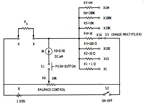
Fig. 2-4. Practical slide-wire resistance bridge.
2.4 PRACTICAL MULTIRANGE SLIDE-WIRE RESISTANCE BRIDGE
Fig. 2-4 shows the circuit of a practical potentiometer-type slide wire bridge for measuring resistance in seven ranges from 0. 1 ohm to 10 megohms. The 10,000-ohm potentiometer, R8, is the balance control, and the dial attached to it reads 0.1 ohm to 10 ohms, with 1 ohm at center scale. This basic range is multiplied by the setting of range switch S3, which selects the appropriate standard resistor (R1 to R7) . The unknown resistance is connected to terminals X-X. The unbalance deflection of d-c micro ammeter M decreases as the standard resistance increases (i .e., as S3 is moved from the lowest toward the highest standard resistor ), becoming only 1. 5 ua in the 1-megohm (x 1M) range and difficult to read. However, on the higher ranges (x 10K to x 1M) , this may be overcome by increasing the voltage of battery B to 6 volts. If a d-c vtvm set to its 1 1/2 -volt range is used as the null detector, no difficulty of this kind is experienced, since on the x 1M range of the bridge, the unbalance deflection is over 0.5 volt.
The dial of potentiometer R8 need be calibrated on only one range (say, the x 1K range ) by successively connecting a number of accurately known resistors in that range to unknown terminals X-X and successively balancing the bridge. However, the dial should be graduated from 0. 1 ohm to 10 ohms-the basic range. If all of the standard resistors are accurate (1 % or better), each range will track with the dial calibration.
The slide-wire bridge has the advantage of simplicity, since it requires a minimum of parts. However, with a single-turn potentiometer of commercial grade, its resistance coverage with any given standard resistor (Rs) is restricted, for accurate reading, to 100: 1 (i.e., from 1.1Rs to 10 Rs--thus, 0.1-10 ohms, 10-1000 ohms, 1K-100K, etc. ). Also, the divisions tend to become crowded in some parts of the dial.
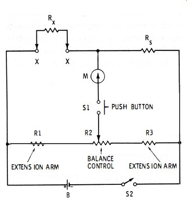
Fig. 2-5. Slide-wire bridge with extension arms.
2.5 SLIDE-WIRE BRIDGE WITH EXTENSION ARMS
In the typical potentiometer-type slide-wire bridge, the ends of the potentiometer are wasted, since the 1.1 Rs and 10 Rs null points occur above the low end and below the high end, respectively, of the potentiometer winding.
Extension arms (R1 and R3 in Fig. 2-5 )sometimes are used to correct this defect by spreading the useful range of the bridge over the entire potentiometer winding. These arms are limiting resistances chosen in value to place the low and high ends of the measurement range at the extreme settings of the potentiometer.
Although a single standard resistor (Rg) is shown in Fig. 2-5 , a set of switched standards may be used in this position, as shown previously in Fig. 2-4.
2.6 BASIC WHEATSTONE BRIDGE
Many of the disadvantages of the slide-wire bridge are resolved by the modern Wheatstone bridge. This is the classic bridge for general-purpose resistance measurement.
Fig. 2-6 shows the basic Wheatstone circuit. In this arrangement, a rheostat, R3, has been substituted for the potentiometer of the slide-wire bridge. A dial attached to R3 reads directly in the resistance setting of this rheostat. Resistors R 1 and R2 are the ratio arms of the bridge. The unknown resistance, Rx, is connected to terminals.
Fig. 2-6. Basic Wheatstone bridge.
At null , Rx/R3 = R2/R 1, from which : Rx = R3 (R2/R1 )
2-7
Thus, the setting of rheostat R3 simply is multiplied by the bridge ratio (R2/R1 ) to determine the value of Rx. In practice, various values of R1 and R2 are switched into the circuit to provide standard multipliers from x 0.001 to x 1000. The total resistance of the rheostat usually is 10,000 ohms, but other values, such as 1000 or 5000 ohms, sometimes are used. A logarithmic taper for the rheostat winding provides a dial having uniform spacing throughout its range.
2.7 PRACTICAL WHEATSTONE BRIDGE
Fig. 2-7 shows a typical circuit of a practical bridge. Here, the rheostat has been replaced with a set of resistance decades (R9 to R48 ). This type of balance control allows closer settings and readings than are possible with a dial-calibrated rheostat; it covers the range from 1 ohm to 11111 ohms in 1-ohm steps.
The bridge ratio is established by resistor R8 in combination with any resistor in the R1-R7 group selected by means of switch S1. At null, the resistance setting of the decades is multiplied by this ratio to obtain the unknown resistance, Rx. The multipliers provided are 0.001, 0.0 1, 0. 1, 1, 10, and 1000; and these multipliers applied to the full resistance range of the decades (1 -1 1,1 11 ohms ) gives the bridge a measurement range of 0.001 ohm to 11 .1 11 megohms.
Various commercial bridges use other methods of ratio-arm switching than that shown in Fig. 2-7. In some instruments, for example, the ratio resistors are switched in pairs, rather than against a single resistor such as R8 .
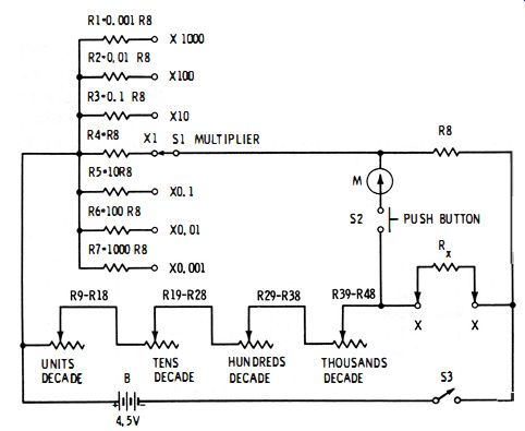
Fig. 2-7. Practical Wheatstone bridge.
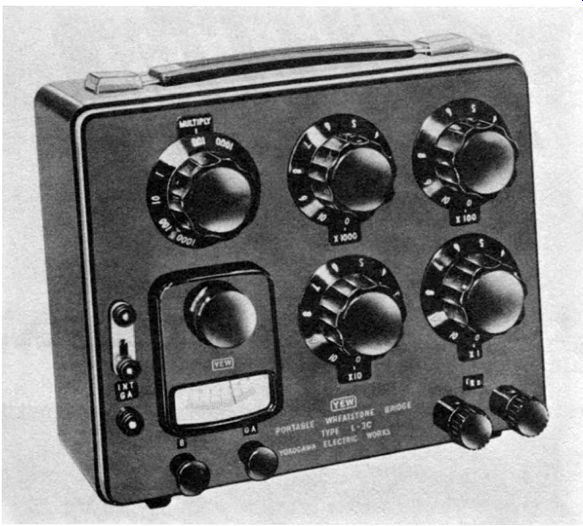
Fig. 2-8 shows a portable bridge of the dial-operated decade type.
This is a completely self-contained model, having an internal battery and permanent galvanometer. Fig. 2-9 shows a laboratory-type bridge.
Courtesy Yokogawa Electric Works, Inc.
Fig. 2-8. Dial-type Wheatstone bridge.
In this latter model, which requires an external battery and galvanometer, the decades are plug type instead of the dial type of the previous model. The five left-hand decades constitute the balance control , while the two right-hand ones form the ratio arms. Fig. 2-10 shows a Wheatstone bridge which has a special guarded construction to eliminate errors due to leakage current, such as that arising from humidity. In this model, each dial of the rheostat arm is behind the panel, so that only the figure indicating the resistance setting shows through a dial window. The multiplier (ratio arms ) dial is seen at top center.
Courtesy Yokogawa Electric Works, Inc.
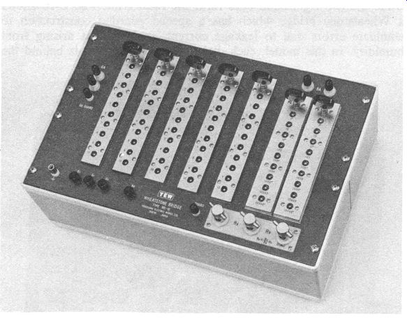
Fig. 2-9. Plug-type Wheatstone bridge.
Courtesy James G. Biddle Co.
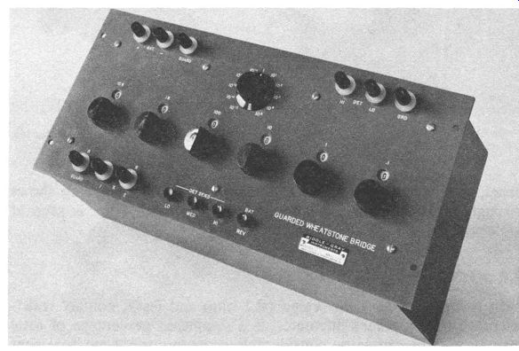
Fig. 2-10. Guarded Wheatstone bridge for close measurements.
2.8 KELVIN DOUBLE BRIDGE
In resistors of very low value (0.1 ohm and less ), contact resistance, which sometimes fluctuates, is a significant percentage of total resistance. This can cause considerable error in current measurement if, for example, an ammeter is connected directly to the current carrying terminals of an ammeter shunt. To reduce such error, some low-value resistors (such as ammeter shunts ) are supplied as four terminal devices which cannot be measured with a conventional The Kelvin double bridge (see Fig. 2-11) accommodates low value, four-terminal resistors. In this circuit, the unknown (Rx) and standard (Rs) both are such resistors. On unknown resistor Rx, C1 and c:! are the current terminals, and P1 and P2 the potential terminals. Similarly, on standard resistor Rs (which is the internal, low-resistance balance control ), c? and c? are the current terminals, and p; and p? are the potential terminals.
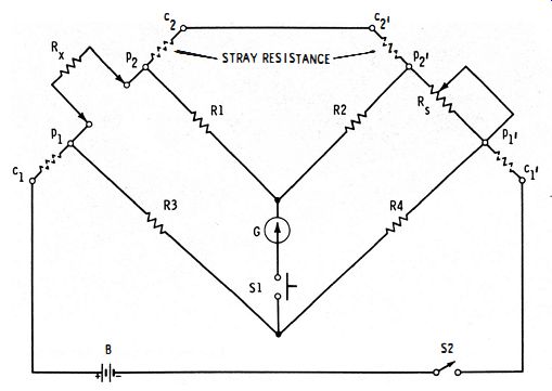
Fig. 2-11. Kelvin double bridge.
Resistor combinations R1-R2 and R3-R4 provide two pairs of ratio arms, giving the circuit the double-bridge configuration from which its name comes. If these resistances are adjusted so that the ratio arms are similar (i.e., R1 /R2 = R3 /R4 ), then at null : 2-8 The auxiliary ratio arms, R 1 and R2, balance out the error due to stray resistance from P2 to p?. Fig. 2-12 shows a Kelvin double bridge for use with an external battery and galvanometer. Note from this photograph that four terminals are provided in the upper left-hand comer of the panel for connection of the unknown resistor to the bridge. Bridges of this type make possible the accurate measurement of resistance in the milliohm range.
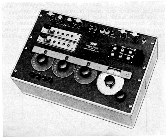
Fig. 2-12. Kelvin double bridge.
2.9 MURRAY LOOP
The Murray loop is an adaptation of the Wheatstone bridge for finding the distance from a test point to a remote ground fault on a line. It is particularly useful in telephone work, but it may be used wherever an extra line is available along the same route as the grounded one.
Fig. 2-13A shows the circuit. Here, line 1 is the spare, "clean" line, and line 2 the grounded one. For the test, the two lines are spliced together, by twisting or cord patching, at a point (such as a distant station) beyond the ground. This forms the loop from which the device takes its name. The four bridge arms are (1) resistor R1; (2) resistor R2; (3) the resistance Ra of line 1 from the test point, around the loop, to the fault; and (4) resistance Rx of line 2 from the test point out to the fault. When R2 is adjusted for null, R1/Ra = R2/Rx•
Fig. 2-13B shows the equivalent bridge circuit.
The resistance per unit length of the wire in the lines must be known beforehand, as must also the length from the test point to the distant splice point. The resistance of line 1 then is R5 = Lrt.
(A) Loop circuit. (b) Equivalent bridge.
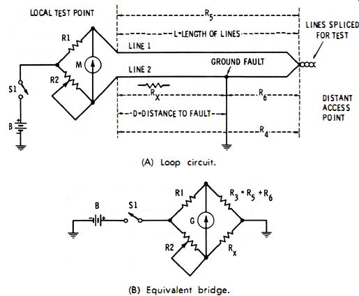
Fig. 2-13. Murray loop.
… where L is the line length and r1 the resistance per unit length of this line. (If L is in miles, r1 is expressed in ohms per mile ; if L is in feet, r1 is in ohms per foot. ) Similarly, the resistance R1 of the entire length of line 2 is equal to Lr2, where r2 is the resistance per unit length of line 2. If both lines are of the same diameter and material, R5 = R4
From the above relationships, the unknown distance, D, from the test point to the fault may be determined. At null :
D = LR2(r1 + r2 ) 2-9 r2 (R1 + R2)
If the two lines have the same resistance per unit length, r1 = r2, and the equation may be simplified:
2.10 VARLEY LOOP
D = 2L(R2 ) R1 +R2
2- 10
The Varley loop is similar to the Murray loop in function and application. In the Varley circuit (Fig. 2- 14) , however, the ratio arms are kept constant and the bridge balanced by adjusting an extra arm, R4.
With this circuit, as with the Murray loop, the resistance per unit length, r1 and r2, of line 1 and line 2, respectively, must be known beforehand. From these values and length L of both lines, the un
known distance, D, from the test point to the fault may then be determined. At null:
Fig. 2-14. Varley loop.
As in the Murray loop, if the two lines are of the same resistance, per unit length, r1 = r2 = r, and the equation may be simplified:
Unlike the Murray loop, the Varley loop (owing to the presence of a third, lumped bridge arm-R4 ) can be used to measure the total resistance of the loop if the lower terminal of the battery is transferred from ground to the junction of R4 and line 2. Some Wheatstone bridges are equipped with a panel switch for quickly selecting either standard bridge operation or Varley loop operation.
2.11 UNIVERSAL GALVANOMETER SHUNT
A sensitive d-c galvanometer may easily be damaged by the high unbalance current of a bridge. To prevent this, some means usually is provided-internally or externally-for shunting the galvanometer to decrease its sensitivity and for progressively removing the shunt (increasing the sensitivity ) as null is approached.
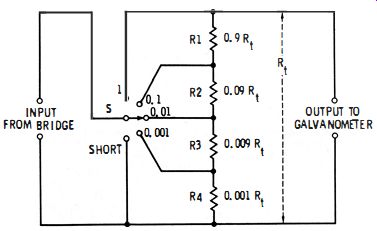
Fig. 2-15. Universal galvanometer shunt.
One such accessory for varying the galvanometer sensitivity is the Ayrton-Mather universal shunt, shown in Fig. 2-15. In this arrangement, which is a kind of attenuator, resistors R1 to R4 (totaling resistance Rd may be separate resistors, as shown, or taps on a single resistor Rt• By means of tap switch S, which selects these resistors, the sensitivity of the galvanometer may be varied at will. In the SHORT position of this switch, the galvanometer has maximum protection.
The total resistance, R to is chosen to equal the critical damping resistance of the galvanometer. The damping of the galvanometer thus is constant at all settings of switch S, since a constant resistance (Rt) is always across the galvanometer. A typical value of Rt in commercial shunts is 1000 ohms, R1 = 900 ohm, R2 = 90 ohm, R3 = 9fl and R4 = In.
2.12 MEGOHM BRIDGE
Very high resistances (several megohms to several tera-ohms ) may be measured with special bridges. While the coverage of a standard bridge may be extended into the megohm range, the very high-resistance standards required for such an extension are usually less accurate than lower-resistance ones, and the extreme division of voltage between at least two of the bridge arms demands a detector so sensitive as to be unstable and susceptible to noise. For these and other reasons, a special megohm bridge is advisable.
Fig. 2-16 shows the basic circuit of a megohm bridge typified by the General Radio Type 544-B. This arrangement is seen to be similar to the conventional Wheatstone bridge except for guard terminals and paths (to minimize the effects of surface resistance of the unknown and standard resistors and of leakage between the unknown terminals and from terminals to ground) and the inclusion of a sensitive d-c vtvm type of null detector (triode V1 ) in the bridge.
The dial of balance-control rheostat R2 is direct reading in meg-ohms, and standard resistors R3 and R 7 are switched by means of S1 to change range (i .e., to multiply the reading of R2 ). In the General Radio bridge, these standard resistors extend from 10K to 100M; R1 is 100K; and R2, 12K.
The d-c input voltage often is high (say, 500 volts ) to permit testing R? under actual working conditions and to provide an off balance output voltage high enough to ensure accurate null adjustment.

Fig. 2-16. Megohm bridge.
2.13 AC BRIDGE MEASUREMENT OF RESISTANCE
Where desired, a resistance bridge may be used with an a-c generator and an a-c detector. One reason for choosing the a-c procedure is the easily obtained high detector sensitivity in such high-input-impedance indicators as vacuum-tube milli-voltmeters, amplifier-type meters, and oscilloscopes.
From Fig. 2-17, the bridge is seen to be conventional . While, for simplicity, a meter (M) is shown as the null detector in this circuit, the detector may be any one of the devices mentioned earlier. The generator usually is an oscillator (conventional test frequencies are 120, 400, 500, and 1000 Hz) . For a sharp null, either the bridge signal must be harmonic-free or the detector must be sharply tuned to the fundamental frequency of the signal.
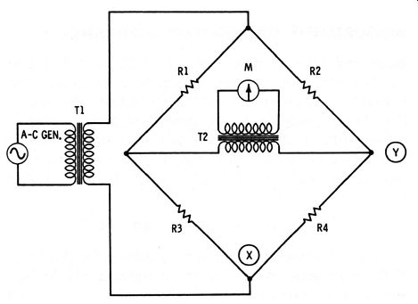
Fig. 2-17. A-c resistance bridge.
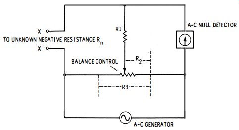
Fig. 2-18. Negative-resistance bridge.
Problems of isolation and strays are more pronounced here than in d-c bridge circuits, and are solved in various ways. For example, well-shielded isolating transformers (T1 and T2 ) are inserted between the generator and bridge, and between the bridge and detector. (In some instances, one of these transformers--often T2--is omitted.) In addition, either point X or point Y (but not both) may be grounded. The shortest practicable leads (preferably shielded) must be employed between generator, bridge, and detector. Additionally, efficient high-frequency operation (20 kHz and beyond) requires that each bridge arm be individually shielded. Reactive components in the bridge arms must be minimal ; otherwise, the bridge will be balanced for complex impedance instead of simple resistance.
(Standards, ratio arms, and balance control therefore are designed for extremely low inductance and capacitance.) The harmful effects of stray reactance are most pronounced at high frequencies and high resistance values.
A standard Wheatstone bridge may be adapted for a-c measurement of resistance by replacing its battery and galvanometer with an a-c source (of suitable voltage output) and an a-c detector. Isolating transformers enhance the accuracy of measurement and should be used unless they are already provided in the generator and detector.
2.14 MEASUREMENT OF NEGATIVE RESISTANCE
Although the circuit shown in Fig. 2-18 is not a conventional bridge, it permits measurement of negative resistance by the null method which is common to bridge operation. An a-c test signal (e.g., 1000 Hz ) is supplied by the generator, and the null is indicated by a high-impedance detector such as a vacuum-tube millivoltmeter.
The unknown negative resistance, Rn, is connected to terminals X-X, and the balance-control potentiometer, R3, is adjusted for null.
At null : 2-13 To prevent swamping the negative resistance, the positive resistance (Rt) of the measuring circuit must be significantly higher than the negative resistance. For best results, (R3 - R:J + l/R1 + [1 /(R2 + Rd )] must be much higher than 10Rn.
Also see: