AMAZON multi-meters discounts AMAZON oscilloscope discounts
The bridge and non-bridge null circuits are widely used in electronic equipment of all kinds. They serve many purposes, ranging in broad categories from signal control and modification to the supply of power. So commonplace have some of these applications become that users take them for granted. In some instances, the contribution made by the null circuit has been noteworthy: economies and simplifications have been effected which might not otherwise have been so readily achieved.
Selected supplementary applications are given in this Section.
These have been chosen for their representative characteristics and complete practicality.
10.1 METER OR RELAY ZERO-SET
Fig. 10-1 shows the use of a bridge circuit to balance the static current out of a milliammeter, micro ammeter, or relay operated in the plate circuit of a vacuum tube or in the collector circuit of a transistor. This circuit is common in vacuum-tube voltmeters, where it is used to set the meter initially to zero.
In Fig. 10-1A, the four bridge arms are made up of resistors R2, R3, R4, and the d-c resistance (Rp) of the tube (see equivalent circuit, Fig. 10-1B). The bridge is balanced (meter or relay zeroed) when rheostat R4 is set to make R4/Rp = R3/R2. Battery B supplies both the plate voltage and bridge voltage. The resistance of R2 and R3 form a bleeder across the battery, and their values are chosen low enough to make the bleeder current at least five times the maximum plate current of the tube. Also, the resistance of rheostat R4 must be at least 10 times the resistance of the meter or relay. These precautions preserve the sensitivity of the circuit to signal voltage.
In Fig. 10-le, the four bridge arms are composed of resistors R 1, R2, R3, and the d-c collector resistance (Rc) of the transistor (see equivalent circuit, Fig. 10-1D). The bridge is balanced (meter or relay zeroed ) when rheostat R3 is set to make R3/Rc = R2/ R1.
Battery B supplies both the collector voltage and bridge voltage (the battery and meter must be reversed for a PNP transistor ). The resistance of R1 and R2 form a bleeder across the battery, and their values are chosen, as in the tube circuit, to make the bleeder current at least five times the maximum collector current of the transistor. Also, the resistance of rheostat R3 must be at least ten times the resistance of the meter or relay. These precautions preserve the sensitivity of the circuit to signal voltage.
(A) Vacuum tube. (b) Vacuum tube equivalent circuit.
(C) Transistor.
(d)Transistor equivalent circuit.
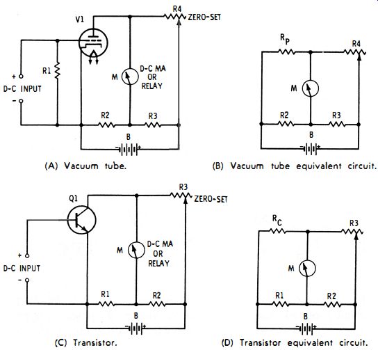
Fig. 10-1. Zero-setting circuit.
10.2 BRIDGE-TYPE METER OR RELAY
For stability, modern d-c vacuum-tube voltmeters and vacuum tube relays use a balanced circuit. As shown in Fig. 10-2A, this is a bridge circuit in which two arms of the bridge are supplied by the d-c plate resistance of matched tubes (Rp1 and Rp2 of tubes V1 and V2, respectively ). The circuit is initially balanced (i.e., static plate current is zeroed out of the meter or relay) by adjustment of potentiometer R1. This changes the ratio of ra to rb (the resistances determined by the setting of the potentiometer contact ) which are in separate arms of the bridge.
(A) Basic circuit. (B) Equivalent circuit.
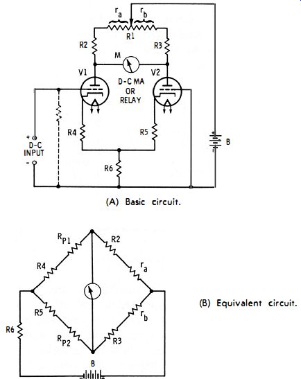
Fig. 10-2. Bridge-type vtvm (relay). After initial balance, the bridge appears
as shown in the equivalent circuit, Fig. 10-2B. Resistance Rpb the d-c plate
resistance of tube V1, changes in response to a d-c signal voltage applied
to the grid of V1, and this unbalances the bridge, deflecting the meter or
closing the relay. Tube V2 acts as an automatic compensator to keep the bridge
balanced (meter zeroed) in spite of drifts of temperature and electrode voltage.
These changes are experienced by both tubes and occur in the same direction
and magnitude, since the tubes are closely matched. When, for example, plate
resistance Rp1 of tube V1 changes as the result of any of these causes (not
because a signal voltage is applied to its grid ), plate resistance Rp2 of
tube V2 changes in the same way and the bridge accordingly remains balanced.
A similar circuit may be arranged for a transistorized voltmeter or relay.
10.3 PHASE SHIFTER
Fig. 10-3 shows the circuit of a bridge-type phase shifter employing only resistance and capacitance. A maximum phase shift of 90 degrees between input and output voltages theoretically is possible in each R-C leg.
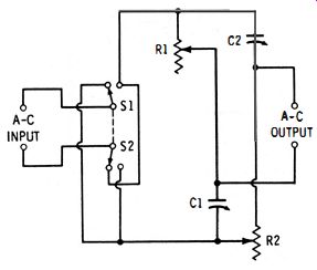
Fig. 10-3. Phase shifter.
Through judicious choice of capacitances and resistances, one may design a shifter of this type which will closely approach the 90 degree performance, so that variation of capacitance and resistance in both legs will give a total phase shift approaching 180 degrees. Then, throwing the dpdt switch S1-S2 will reverse the input and provide an additional 180 degrees of variation, to give a total phase-shift range of 0-360 degrees.
10.4 BALANCED MODULATOR
A four-diode semiconductor bridge makes a simple and convenient balanced modulator which gives good results if the diodes are closely matched for forward and reverse conduction and have better-than average temperature stability.
Fig. 10-4 shows one type of bridge modulator circuit. For simplicity, transformers, capacitors, and compensating resistors have been omitted. Since the bridge is automatically in balance because the internal resistances of the diodes are all equal, the carrier voltage is nulled and cannot appear at the output terminals. However, diode nonlinearity results in modulation of the carrier by the modulating voltage, and the product of this modulation does appear at the output. This product consists of the upper sideband (f" + fill ) and lower sideband (fc - fill )'
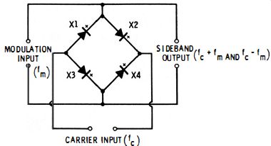
Fig. 10-4. Balanced modulator.
10.5 DC-AC CONVERTERS
Amplification of a d-c voltage is often obtained by (1) converting the direct current to a proportionate a-c voltage, (2) amplifying the latter with an a-c amplifier, and (3) rectifying the output of the amplifier. In this way, the stability of an a-c amplifier may be used to advantage, and this stability is usually superior to that of a d-c amplifier. A d-c-to-a-c converter changes the direct current to alternating current for presentation to the amplifier.
Fig. 10-5 shows two bridge-type converter circuits. In Fig. 10-5A, two closely matched semiconductor diodes (X1 and X2 ) are used as the variable elements. Potentiometer R 1 is the balance control.
The four arms of this bridge are ra, rb, X1 + R2, and X2 + R3.
When the bridge has been initially balanced (with a-c power supplied, the DC SIGNAL INPUT terminals open, and R1 adjusted for zero reading of an a-c null detector connected to the AC SIGNAL OUTPUT terminals ), no a-c voltage appears at either the DC SIGNAL INPUT terminals or at the A-C SIGNAL OUTPUT terminals, if the diodes are perfectly matched and the circuit is adequately shielded. When a d-c signal of the polarity shown is applied, diode X1 conducts forward current; this produces a d-c voltage drop across R2 and unbalances the bridge, causing an a-c voltage proportional to the d-c signal voltage to appear at the output terminals. A d-c signal of opposite polarity causes a d-c voltage to appear across R3, resulting in an a-c output 180 degrees out of phase with the first.
In Fig. 10-5B, two varactors (X1 and X2 ) are the d-c-sensitive elements of the bridge. The four arms of this bridge are C1, C2, X1, and X2. The bridge is automatically in balance if the capacitors and varactors have been closely matched for capacitance ; otherwise, one of the capacitors may be made variable for use as a balance control. At balance, no rf voltage reaches either the D-C SIGNAL INPUT terminals or the R-F SIGNAL OUTPUT terminals. When a d-c signal is applied, it changes the varactor capacitance by an amount proportional to the d-c voltage and causes an rf voltage proportional to the d-c voltage to appear at the output terminals.
(A) Diode type.
(B) Varactor type.
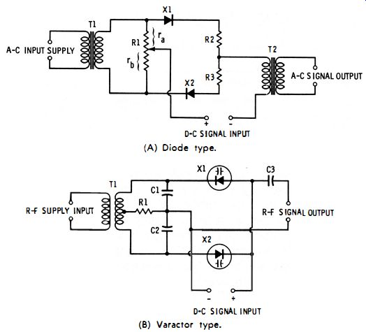
Fig. 10-5. D-c to a-c converters.
10.6 R-C-TUNED OSCILLATORS
(A) Wien bridge type.
(b) bridged T type.
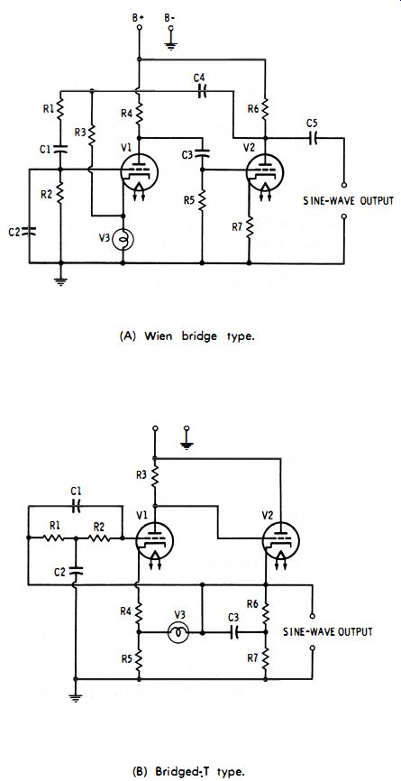
Fig.10-6. RC tuned oscillator.
Null circuits provide a convenient means for the resistance-capacitance tuning of audio and supersonic oscillators. Moreover, the selectivity of these circuits reduces distortion in the output of such oscillators to an extremely small amount. Virtually all types of null circuits have been used for this purpose.
Fig. 10-6 shows two circuits of R-C-tuned oscillators. Fig. 10-6A employs a Wien bridge. In this circuit, the four bridge arms are C1 + R1, C2 + R2, R3, and V3 (a tungsten-filament lamp). See Section 7.3, Section 7, for a description of the frequency-sensitive Wien bridge. This oscillator circuit is a two-stage amplifier in which positive feedback through the bridge produces oscillation, and negative feedback through resistor R3 and a voltage-sensitive resistor (the filament of lamp V3) stabilizes the circuit and keeps the output constant over the tuning range. At the frequency to which the bridge is tuned, the phase is correct for oscillation and so is the amplitude of the positive feedback with respect to that of the negative feedback.
Oscillation therefore occurs at that one frequency; at other frequencies, the negative feedback predominates and prevents oscillation, and this action results in the low distortion which is characteristic of the Wien-bridge oscillator. For tuning, C1 and C2 may be varied simultaneously, and R1 and R2 switched together to change frequency ranges. Or, R1 and R2 may be varied simultaneously, and C1 and C2 switched together to change ranges. The former method has proved to be the more practicable in most cases.
Fig. 10-6B employs a bridged-T network which is a variation of the type described in Section 9. Its operation is similar to the Wien-bridge oscillator described previously.
Most commercial bridged-T oscillators are tuned by varying R1 and R2 simultaneously, and the frequency ranges are changed by switching capacitors C1 and C2 in pairs.
Other null networks used to tune oscillators are the twin T and the LC-type bridged T. There is some objection to the twin T, except for single-frequency applications" because its requirement that three components be varied simultaneously for tuning and the other three switched together for range changing renders it somewhat inconvenient for variable-frequency use. The LC-type bridged T makes possible a very low distortion oscillator, but the large values of inductance and capacitance it requires at audio frequencies preclude its use in smoothly variable instruments. The R-C network shown in Fig. 10-3 is used occasionally in bridge-type phase-shift oscillators, but it does not compete significantly with the Wien bridge and RC-type bridged T.
10.7 RC-TUNED AF AMPLIFIERS
Resistance-capacitance null circuits make possible the tuning of tube- and transistor-type audio-frequency amplifiers without the use of inductors or of heterodyne circuits. Fig. 10-7 shows two tuned amplifier arrangements.
In this system of tuning, a null network is placed in a negative feedback loop around the amplifier. Negative feedback then cancels the gain of the amplifier on all frequencies except the null frequency of the network. The amplifier thus is able to transmit that frequency only. It is in this way that the entire system (amplifier plus network ) becomes a bandpass filter, although the network alone is a band-rejection filter.
(A) Twin-T type. (b) Hall type.
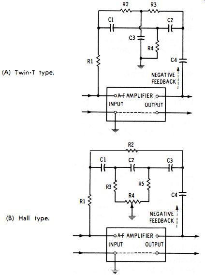
Fig. 10-7. R-c: tuned IF amplifiers.
In Fig. 10-7 A, a twin-T network is used. (See Section 9.6. Section 9, for a description of the twin T. ) In this network, C1 = C2 = Ih C3, R1 = R2 = 2R3, and the pass frequency is f = 1/ (2 pi R1Cd . Continuously variable tuning may be obtained with
a three-gang rheostat for the resistances, and the frequency range may be changed by switching capacitors C1, C2, and C3 together. Resistor R1 decreases the loading effect of the network on the high-impedance input of the amplifier, and capacitor C4 provides d-c blocking.
In Fig. 10-7B, a Hall network is used as the tuning circuit.
(See Section 9.7, Section 9, for a description of the Hall network.) The advantage of this null circuit is its use of a single potentiometer (R4 ) for tuning. The frequency range may be changed by switching capacitors C1, C2, and C3 together. Resistor R1 decreases the loading effect of the network on the input circuit of the amplifier, and capacitor C4 provides d-c blocking. Resistors R3 and R5 limit the extremes of potentiometer R4.
Sometimes a preamplifier stage is operated ahead of a tuned amplifier, and a cathode follower or emitter follower after the amplifier to isolate the null network from the effects of the signal source and the load.
The selectivity of the R-C-tuned amplifier is good. Nevertheless, it can be sharpened considerably by providing untuned positive feedback, in addition to the tuned negative feedback, and increasing this positive feedback to a point just short of oscillation.
10.8 DISTORTION METERS
Total harmonic distortion is measured with the setup shown in Fig. 10-8. In this arrangement, an amplifier (B) under test is driven by a low-distortion oscillator (A) at the desired test frequency and is terminated with the correct load, R1. Shunting this load are an rms voltmeter (Ml) and a null device (C) tunable to the test frequency. At the output of the null device is a second rms voltmeter, M2.
LOW DISTORTION OSCILATOR (A) (B) RMS VOLTMETER (C) RMS VOLTMETER
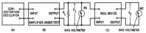
Fig. 10-8. Setup for harmonic distortion measurement.
Meter M1 indicates the combined voltage E1 due to the test signal fundamental and all harmonics created by distortion in the amplifier. However, the null device rejects only the fundamental voltage, and passes any remaining voltage (E2) to meter M2. (If the amplifier output signal contained no harmonics, M2 would read zero. ) Voltage E2 therefore is proportional to the total harmonic content. For economy, a single meter is often used with a switch for connecting it to the input of the null device for reading Eh and to the output for E2. The total harmonic ( distortion) percentage is determined from the two voltages :
10-1
Suitable null circuits for this application are the resonance bridge (see Sections 7. 1 and 7.2, Section 7) and the L-C-type bridged T. The bridged T offers the advantage of a common ground between its input and output terminals. However, neither the resonance bridge nor the bridged T may be smoothly tuned over a wide range of frequencies. The resistance-capacitance bridge and non-bridge null circuits may not be used directly for accurate measurements by this method, because they attenuate harmonics, as well as the fundamental, and do this at a nonuniform rate.
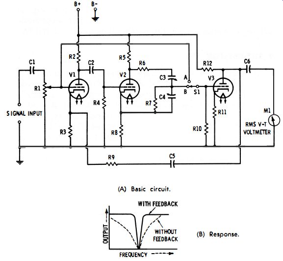
Fig. 10-9. R-c tuned variable-frequency distortion meter. (A) Basic circuit.
(B) Response.
For continuous tuning of a distorted meter, a Wien bridge may be used, provided it is included in an amplifier around which a large amount of negative feedback is provided. This gives the simplicity and compactness of the R-C circuit, while affording continuously variable tuning. Fig. 10-9A shows the basic circuit of a tube-type instrument of this type. Here, the tunable network (C3-C4-R6-R 7) is inserted between two amplifier stages. Continuously variable tuning is provided by the dual variable capacitor (C3-C4 ), and ranges are changed by switching identical resistors R6 and R 7 together. Negative feedback around the entire circuit is supplied by the C5-R9 path. Fig. 10-9B shows how feed1! ) reads the full input voltage E1 (fundamental plus harmonics ); when S1 is at B, M1 reads the total harmonic voltage, E2. The harmonic percentage may be determined from these voltages by use of equation 10-1. Alternately, E1 may be preset to a reference point on the meter scale by adjustment of gain-control potentiometer R1, whereupon the E2 deflection may be read directly as total distortion percentage.
Still another method of measuring distortion consists of a wave analysis. Here, the fundamental-frequency voltage (Ef ) and each harmonic voltage (Eh2, Eh3, Eh4 ... Ehn) are separately measured.
The strength of any one of the harmonics then may be compared with that of the fundamental. Or the total distortion may be calculated as the vector sum of the harmonic voltages compared with the fundamental voltage:
10-2
A highly selective tuned bandpass filter is needed for tuning successively to the fundamental and each of the harmonics. Continuously variable, tuned amplifiers, such as those shown in Fig. 1 0-7, will be adequate in this filter function if harmonic amplitudes no smaller than 1/100th of the fundamental amplitude are required.
10.9 THERMISTOR BRIDGE
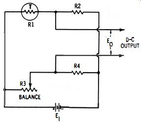
Fig. 10-10. Thermistor bridge.
A thermistor is a special temperature-sensitive resistor. It can be made one arm of a bridge, as shown in Fig. 10-10 (the thermistor might be mounted in the end of a temperature probe ). The bridge is balanced by adjustment of rheostat R3. At null, the output voltage (Eo) is zero for the temperature (td to which the thermistor is exposed during the adjustment:
R1 = (R2R3 ) /R4.
When the thermistor subsequently is exposed to a different tempera-ture (t2 ) , its resistance (R1) changes proportional to the new temperature, and the bridge unbalances. The unbalance output voltage (Eo) then is proportional to the temperature change (t2 - t1 ) ' The d-c output of the thermistor bridge may be amplified to increase the sensitivity of the circuit to small temperature changes. The amplifier can drive a recorder for a continuous record of temperature variation.
Another way to use this setup is to balance the bridge at each temperature of interest, determining the thermistor resistance from the relationship R1 = (R2R3 ) /R4, and then to refer the R1 value to a temperature chart based on the thermistor used, to obtain the temperature in degrees. Rheostat R3 may be calibrated in degrees.
10.10 STRAIN-GAUGE BRIDGE
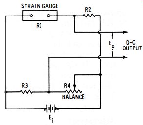
Fig. 10-11
Fig. 10-11 shows the circuit of a bridge in which a strain gauge is one arm. (A strain gauge is a stress-sensitive resistor. ) The active strain gauge (R 1) is cemented to the structure to be strained. An inactive gauge (i.e., one of the same type as R1 but not mounted on the structure ) sometimes is used for the R3 arm.
The bridge is balanced under zero-stress conditions by adjustment of rheostat R4, and the output voltage (Eo) accordingly is zero : R1 = (R2R3)/R4. When the active strain gauge subsequently is strained, its resistance changes and the bridge unbalances. The unbalance voltage, Eo, then is proportional to the strain suffered by the structure to which the gauge is attached. The d-c output of the strain-gauge bridge may be amplified to increase the sensitivity of the circuit to small strain values. The amplifier can drive a suitable recorder, if a permanent record is desired.
10.11 PHOTOCELL BRIDGE
A bridge circuit is convenient for balancing the dark current out of the output of a photoconductive-type photocell. Fig. 10-12 shows the simple circuit. In this arrangement, the photocell internal resistance ( R1 ) forms one arm of the bridge.
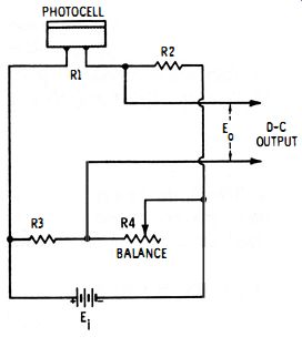
Fig. 10-12. Photocell bridge.
With the cell completely darkened, the bridge is balanced by adjustment of rheostat R4, reducing to zero the dark output voltage (Eo) : R4 = (R2R3 ) / R1 . When the cell subsequently is illuminated, its resistance decreases and the bridge unbalances. The unbalance voltage, Eo, then is proportional to the light intensity. The d-c output of the photocell bridge may be amplified to increase the sensitivity of the circuit to dim light. The amplifier can drive a recorder, or actuate a d-c relay which requires higher current than that delivered directly by the bridge.
10.12 PRESSURE MEASUREMENT
One type of pressure sensor uses a strain gauge cemented to an elastic metal disc. The disc is mounted in a suitable tube or chamber, where it is subjected to the pressure under study. This pressure distends the disc, stretching the gauge and causing a proportionate change in gauge resistance.
The resistance is measured with a d-c bridge in which the pressure sensor is one arm. This resistance is converted to pressure units by reference to a prior calibration of the strain gauge. The circuit is essentially the same as shown in Fig. 10-11. The dial of rheostat R4 may be calibrated to read directly in pressure units, thus eliminating calculations or references to tables.
10.13 GAS SNIFFER
An instrument for detecting flammable or explosive gases uses a d-c bridge circuit similar to Fig. 10-10. In the gas "sniffer," however, the thermistor in the upper left arm in Fig. 10-10 is replaced by a gas sensor. The latter consists essentially of an open filament which is exposed by blowing across it some of the air suspected of containing dangerous gas.
Resistance R2 is chosen, with respect to battery voltage Eh so that the current through the sensor filament is of the correct value to keep the filament just warm. The bridge is balanced in the absence of gas by adjustment of rheostat R3. A d-c milliammeter or micro ammeter at the output terminals then reads zero. When a flammable gas subsequently is blown across the filament, some of the gas burns and the heat changes the resistance of the filament. This causes the bridge to unbalance, giving an output voltage which is proportional to the generated heat and being therefore indicative of the concentration of the gas. In some sniffers, a red area is provided on the meter scale to indicate the danger level.
10.14 TEMPERATURE MEASUREMENT WITH POTENTIOMETER
The d-c millivolt potentiometer is widely used for precise measurements of temperature, both in the laboratory and in the field.
In this application, a thermocouple is the temperature sensor, and its d-c output in millivolts (as indicated by the potentiometer at balance ) is referred to a thermocouple table to determine the corresponding temperature in degrees. In portable potentiometric temperature instruments intended for rapid readings, the slide-wire dial is graduated in degrees for direct reading.
10.15 CRYSTAL FILTER
Fig. 10-12 (A) Circuit. (b) Equivalent bridge.
The crystal filter, which affords high selectivity in communications receivers, employs an intermediate-frequency bridge circuit.
Fig. 10-13A shows a representative circuit, and Fig. 10-13B the equivalent bridge. In a receiver, the filter is inserted between two i-f stages or between the converter (first detector) and first i-f stage.
In Fig. 10-13A, the dual variable capacitor, C2-C3, is the tuning control, and variable capacitor C4 is the phasing control. The function of the latter is to balance out the capacitance of the crystal holder; if this operation were not performed, the holder capacitance would transmit the unwanted signals through the system. The phasing control allows adjustment of the filter to place a rejection notch in its response at the proper point for eliminating interfering signals or heterodynes.
At balance, governed by the setting of phase control C4, Cx/C2 = C4/C3, and C4 = (C3Cx ) /C2, where Cx is the capacitance of the crystal holder. But since C2 = C3 at all settings of the dual capacitor, 2-C3, then C4 = Cx.
10.16 MAGNETIC-FLUX MEASUREMENT
A d-c bridge may be used for the measurement of magnetic flux if one of the bridge arms consists of a sensor whose resistance is proportional to the strength of an applied magnetic field. Such a sensor may be a semiconductor-type magnetoresistor or a small coil of bismuth wire. The circuit is similar to Fig. 10-12, with the photocell replaced by the flux sensor, and a d-c milliammeter or microammeter used as the output indicator.
The bridge is balanced initially by adjustment of rheostat R4, with all flux absent. When the sensor subsequently is exposed to a magnetic field, its resistance changes, the bridge accordingly un-balances, and the unbalance current (indicated by the output meter) is proportional to the flux density. The meter scale or the dial of rheostat R4 therefore may be calibrated to read directly in flux units.
10.17 NEUTRALIZATION OF RF AMPLIFIER
Feedback through the grid-plate capacitance of a tube can cause a radio-frequency amplifier to oscillate. This nuisance, which is pronounced in triodes, may be overcome by neutralization of the amplifier stage. Neutralization requires feeding back some of the r-f energy from the output in proper phase to counteract the effects of the tube capacitance. In Fig. 10-14A, Cn is the neutralizing capacitor used for this purpose. When its capacitance is adjusted to the correct point, oscillation ceases (or if the stage is temporarily disabled, all transmission through it due to the tube capacitance is canceled).
(A) Circuit. (B) Equivalent bridge.
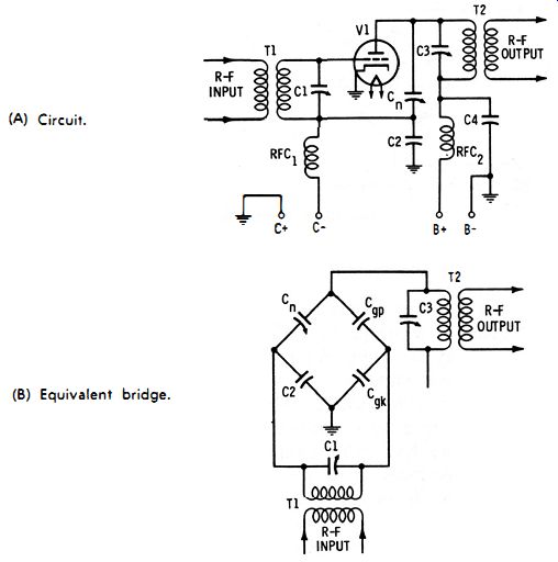
Fig. 10-14. Neutralization of r-f amplifier.
The neutralization circuit is a four-capacitor bridge, as shown in Fig. 10-14B. Here, the bridge arms are neutralization capacitor Cn, bypass capacitor C2, tube grid-plate capacitance Cgp, and tube grid-cathode capacitance Cgk• (Actually, the input capacitance C1 of the stage is in parallel with Cgk and must be added to the latter.) Adjustment of neutralizing capacitor Cn balances the bridge. At null : 10-3 R-f transmission through the grid-plate capacitance thus is reduced to zero.
(A) Circuit. (B) Equivalent circuit, zero input. (C) A positive, B negative. (D) A negative, 8 positive.
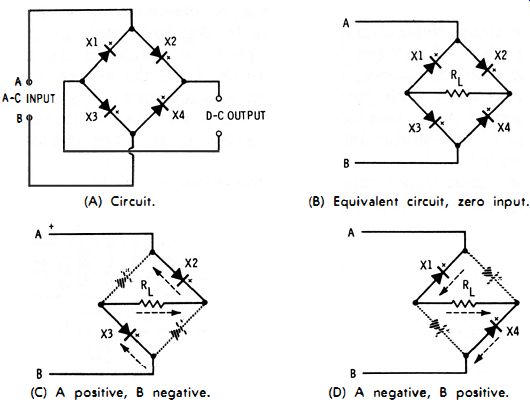
Fig. 10-15. Full-bridge rectifier.
10.18 BRIDGE RECTIFIER
A bridge rectifier consists of four diodes connected so that they are the arms of a bridge (see Fig. 10-15A). Either tubes or semiconductors may be used. With filament-type tubes, however, three separate filament supplies are necessary, since only two cathodes are common in the bridge. The bridge rectifier gives full-wave rectification from a two-terminal a-c supply, such as a power line or a transformer having no center tap.
Full-wave rectification by this circuit (see equivalent circuit, Fig. 10-15B) results from alternate conduction by pairs of the bridge arms. When, for example, a-c input terminal A is positive (Fig. 10- 15C), diodes X2 and X3 conduct (being forward connected at this polarity ) and diodes X1 and X4 block (being reverse connected). Electron current therefore flows from left to right through the load (Rd. When terminal B is positive on the succeeding half-cycle of a-c input, diodes X1 and X4 conduct and diodes X2 and X3 now block. Again, however, electron current flows through the load from left to right. Thus, the d-c output flows in the same direction during each half-cycle of ac input--or, full-wave rectification results.
(A) Three-quarter bridge.
(B) Half bridge.
(c) Quarter bridge.
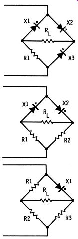
Fig. 10-16. Fractional-bridge rectifiers.
For simplicity and economy, and sometimes for emergency repair, diodes occasionally are replaced with resistors in some of the bridge arms. In Fig. 10-16A, for example, resistor R 1 has been substituted for one diode. This configuration thus is termed a three-quarter bridge. In the half bridge (Fig. 10-16B), resistors R1 and R2 replace two of the diodes. In the quarter bridge (Fig. 10-16C), only one diode (Xl ) remains. Each of these circuits may be analyzed in the same way as the full bridge in Figs. 10-15B, C, D. Neither of the fractional bridges is as efficient as the- full bridge, the quarter bridge being the least efficient. A further disadvantage of the quarter bridge is the presence of R1 and R2 always across the ac supply as a load.
The circuits shown here are for single-phase operation. Somewhat more complicated arrangements are needed for polyphase operation and can be found in electrical handbooks.
10.19 VOLTAGE-SENSITIVE BRIDGES
If a varistor-a voltage-sensitive resistor (e.g., thermistor, Thyrite resistor, filament-type lamp, or forward-connected diode )-is used as one of the arms of a d-c bridge, null will occur at only one input voltage for any combination of resistances in the other arms of the bridge. Thus, the output of the bridge will be zero for some discrete value of input voltage.
This phenomenon is utilized in voltage-sensing devices and in control equipment in which an output voltage is required to fall to zero at a prescribed value of input voltage. The voltage-sensitive bridge is used occasionally as a frequency multiplier, since in response to an applied a-c voltage the bridge output voltage goes through zero four times during each input half-cycle.
10.20 BRIDGE AS SIMPLE ANALOG COMPUTER
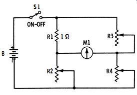
Fig. 10-17. Simple analog computer.
There are several ways of using null circuits as analog computers (electronic slide rules ).
Fig. 10-17 shows a Wheatstone bridge adapted to this purpose.
In this circuit, R1 equals 1 ohm and is a precision resistor. Each of the other arms contains a variable resistor. At null, R4 = (R2R3 )/ R1 = (R2R3/ l =R2R3.
Since R4 thus equals the resistance of R2 times that of R3, multiplication can be performed by setting R2 equal to the multiplicand, setting R3 equal to the multiplier, balancing the bridge by adjustment of R4, and reading the product from the null setting of R4. Similarly, since R4/R3 = R2, division can be performed by setting R4 equal to the dividend, setting R3 equal to the divisor, balancing the bridge by adjustment of R2, and reading the quotient from the null setting of R2.
The degree of accuracy depends upon the closeness with which resistances R2, R3, and R4 can be read. Series-connected decade boxes in each of these arms will permit readings in 1-ohm steps.
Next to be preferred are precision 10-turn potentiometers. Operation of the circuit is independent of the voltage of battery B. However, means must be provided for reducing this voltage when the [...]