AMAZON multi-meters discounts AMAZON oscilloscope discounts
Inductance bridges may be regarded as forming the second large class of a-c bridges. In general configuration, the inductance bridge resembles the capacitance bridge and the resistance bridge. It differs from the capacitance bridge, however, in the presence of inductors in one or more of its arms and also in the respect that it can, in some versions, compare unlike impedances, i.e., inductance with capacitance.
As a class, inductance bridges cover the range from 0.1 nano-henry to 10,000 henrys with accuracies reaching ± 0.1 % or better. Like the resistance bridge and capacitance bridge, the inductance bridge may be either rudimentary or complex to suit individual demands.
This Section describes bridges for the measurement of self-inductance and mutual inductance. Representative types in each category are shown.
4. 1 BASIC SLIDE-WIRE INDUCTANCE BRIDGE
Fig. 4-1 shows the most rudimentary inductance bridge. In this arrangement, the variable balancing resistor is a single strand of resistance wire (the slide wire) tautly stretched between points A and B (or wound around a form having a circular cross section) and provided with a sliding contact (the slider). The wire has a uniform cross section and is of constant composition, so its resistance is directly proportional to its length.
As the slider is moved along the wire, it divides the latter into two parts : D1, the length from point A to the slider, which has a resistance of R1 ; and D2, the length from point B to the slider, which has a resistance of R:?
Thus, the resistance increases on one side of the moving slider and decreases on the other side.
The bridge is composed of unknown inductor Lx (connected to terminals X-X), standard inductor Ls, and the two sections (R1 and R2 ) of the slide-wire variable resistor, which provide the ratio arms.
The bridge is balanced by moving the slider along the wire until the detector response is minimum. At this null point, Lx/L = RtlR2, and from this relationship the unknown inductance may be determined in terms of the standard : 4-1

The total resistance of the slide wire is unimportant to the calculation. So also are the actual resistance values on each side of the slider.
In fact, distances D1 and D;! may be measured in inches, centimeters, or arbitrary linear units and used in the calculation in place of resistances R1 and R2 :

4-2
For this reason, the basic slide-wire bridge is convenient for emergency measurements of inductance, since it requires only a standard inductor and a length of bare resistance wire stretched along a meter stick or yardstick, in addition to a generator (e.g., an audio oscillator) and a detector (e.g. , a-c vtvm, oscilloscope, or high-resistance headphones ) . Sometimes, it is more convenient to read the position of the slider with respect to the total length (D3 ) of the wire than to measure Dl and D2 separately. In such an instance :
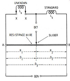
Fig. 4-1. Diagram of a basic slide-wire inductance bridge.
It is apparent from either equation 4-2 or 4-3 that the unknown (Lx) is equal to the standard (Ls) when null occurs with the slider halfway between A and B (i .e, when D1 = D2, making DdD2 = I) . Also, the slider must move to the right of center when Lx > L", and to the left of center when Lx < Ls.
If the wire is long (say, 1 meter or more ), little difficulty is experienced in measuring inductances over the range 0.01L to 100L", provided a sensitive detector is used. Unless the wire has reasonably high resistance (large ratio of length to thickness ), however, the current may heat it enough to impair the accuracy of measurement.
4.2 POTENTIOMETER-TYPE SLIDE-WIRE INDUCTANCE BRIDGE
A more compact version of the slide-wire inductance bridge, like the similar version of the resistance and capacitance bridges, substitutes a wire-wound potentiometer for the slide wire. Fig. 4-2 shows this arrangement.
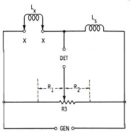
Fig. 4-2. Potentiometer type slide-wire inductance bridge.
In this circuit, the balancing potentiometer has a total resistance R3. At any setting, R3 = R1 + R2, the sum of the resistances between the contact blade and the low end, and the contact blade and the high end, respectively, of the resistance element. Resistances R1 and R2 determine the bridge ratio.
At null, the unknown inductance (Lx) is determined from the standard inductance (Ls) and the resistance ratio:
4-4
The potentiometer dial may be calibrated to read directly in micro-henrys, millihenrys, or henrys by locating the null points for a number of known inductances connected successively at Lx. It may also be calibrated with the aid of equation 4-4, in terms of measured R1 and R2 values. If the potentiometer dial already reads directly in resistance setting (as the dial of a multiturn potentiometer often does ), the unknown inductance may be calculated with reference to that setting:
Lx = Ls[R1/ (R3 – R1)]
4-5
…where RJ is the resistance setting indicated by the dial, R3 is the total resistance of the potentiometer.
Like the basic slide-wire inductance, the potentiometer-type circuit is simple and economical . However, it has three disadvantages : (1) because of stray reactances in the circuit, Lx values lower than 100 uH often cannot be measured accurately; (2) unless the potentiometer has a special taper, such as logarithmic, the graduations will crowd at one end of the dial, seriously impairing readability and accuracy-and for that reason, the inductance range with any standard inductor Ls should not exceed 0. 1 to 10 times Ls, even though the potentiometer affords a wider range ; and (3) a complete null occurs only if losses in the unknown inductor equal those in the standard inductor.
The degrading effect of stray reactances in the useful ranges of the bridge may be reduced somewhat by keeping the potentiometer resistance, R3, reasonably low-say, 5000 ohms. The wasted ends of the potentiometer in the simple circuit may be saved by means of extension arms (such as R1 and R3 in Fig. 4-3 ) which allow the useful 100:1 inductance range to be spread over the entire resistance range of the potentiometer.
4.3 PRACTICAL POTENTIOMETER-TYPE SLIDE-WIRE INDUCTANCE BRIDGE
Fig. 4-3 shows the circuit of a practical bridge using a 5000-ohm wirewound potentiometer (R2) as the balance control . This bridge covers the range from 100 uh to 100 hy in three steps : 100 uh-10 mh, 10 mh-1 hy, and 1-100 hy. The inductance ranges are selected by switching standard inductors (L1, L2, L3 ). The 100-ohm non-inductive resistors, R1 and R3, provide the extension arms mentioned in Section 4.2.
Any convenient test frequency may be employed, up to about 5 kHz. Best stability is obtained, however, when the generator is coupled to the bridge through a shielded transformer. It is advisable also to insert a transformer between the bridge and detector, but this second transformer may be omitted if the first one is used, especially if the lower DET terminal is grounded.
This bridge may be calibrated by balancing it with a number of accurately known inductors connected successively to terminals x-x, and inscribing the potentiometer dial accordingly. Only one range need be calibrated in this manner; the others will track if the values of L I, L2, and L3 are all accurate. Thus, the lowest range (0.0001 -0.0 1 hy ) may be calibrated and the A, B, and C settings of switch S 1 then used to multiply this basic range by 1, 100, and 10,000, respectively.
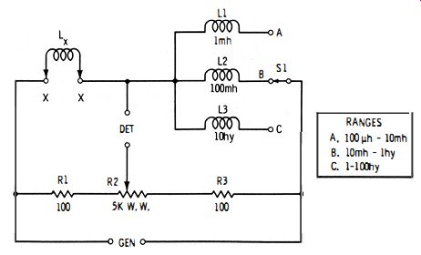
Fig. 4-3. Practical potentiometer-type slide-wire inductance bridge.
(A) Series compensation of standard.
(C) Series Compensation of unknown.
(B) Parallel compensation of standard.
(D) Parallel compensation of unknown.
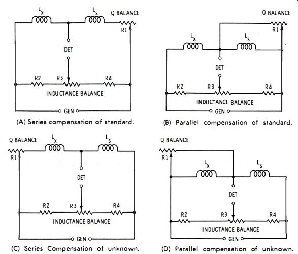
Fig. 4-4. Slide-wire inductance bridge with Q balance.
The null balance is sharp if losses in the inductor under test (Lx ) equal those in the standard inductor (Ls) . Since low-loss inductors customarily are used as the standards, this usually-but not always-means that a sharp null indicates low loss in the inductor under test. However, a broad null can also reveal that the standard is inferior to the test inductor.
4.4 THE NEED FOR Q BALANCE
The preceding sections explain that a complete null is impossible with a simple slide-wire bridge unless the losses in the unknown and standard inductors match. The reason for this is the complex nature of the practical inductor as an impedance network (inductance and resistance in combination, the resistive component representing the losses ). In order to obtain a complete null in most practical situations, separate balances are required for the resistive and reactive components, and this makes the bridge somewhat more complicated.
It is convenient to express the relationship between losses (resistive component ) and inductance (reactive component ) as the figure of merit or Q of the inductor. Numerically, Q = XLjR = tangent of the phase angle of the equivalent LR network. A low-loss inductor has a high Q. In somewhat more specific terms, the original statement may be re-phased thus: A complete null is obtained only when the Q of the unknown inductor equals that of the standard inductor. When the Q's are unequal, as they almost always are in practice, enough resistance must be added in series (sometimes in parallel ) with the lower-loss inductor to reduce its Q to that of the higher-loss inductor. Addition of resistance to one or the other of the inductors will complete the balance of the bridge.
Fig. 4-4 shows how a Q-balance rheostat may be added to the slide-wire inductance bridge. In Figs. 4-4A and 4-4B, the standard inductor (Ls) is the higher-Q component, and the resistance-balance rheostat ( R1 ) is added in series (Fig. 4-4A) or parallel (Fig. 4-4B) with Ls. In Figs. 4-4C and 4-4D, the unknown inductor is the higher-Q component, and the resistance-balance rheostat (R1) is added in series (Fig. 4-4C) or parallel (Fig. 4-4D) with Lx. In use, the bridge is balanced first for inductance by adjusting potentiometer R3 for minimum response of the detector. Then, rheostat R1 is adjusted to improve the null. Additional adjustments of R1 and R3, alternately, will give complete null (zero detector output ). The resistance of R1 does not enter into the calculation of unknown inductance. Nor does the resistance of R3 enter into the calculation of Q (see the next section ).
For complete null, the resistance of R 1 must be adjustable to the equivalent resistance of the opposite inductor. A dial attached to this rheostat may be calibrated to read directly in Q; however, this dial will read correctly only at the calibration frequency. All complete inductance bridges are equipped with such a Q balance.
Fig. 4-5 shows how a Q-balance rheostat is included in a universal bridge so that it may be switched in series with either the unknown or standard inductor, whichever has the higher Q (See Section 3.4 and Fig. 3-5 for an explanation of the universal bridge.) This bridge is convenient for checking an unknown inductor (Lx) against any available inductor (L,) whose inductance, but not necessarily its Q, is known. When switch S1 is in position A, the Q-balance rheostat (R3 ) is in series with standard inductor Ls ; when S1 is in position B, rheostat R3 is in series with unknown inductor Lx.
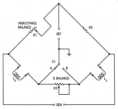
Fig. 4-5. Universal bridge with Q balance.
4.5 INDUCTANCE COMPA R1SON BRIDGE
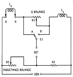
Fig. 4-6. Inductance comparison bridge.
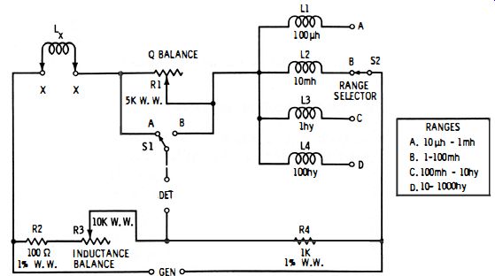
Fig. 4-7. Practical multirange inductance comparison bridge.
A common inductance bridge merely substitutes inductance arms for two of the resistance arms in the Wheatstone bridge, retains the other two resistance arms--the ratio arms--to complete the basic circuit, and adds a Q balance. Because of the similarity of the two bridges, the inductance type is sometimes familiarly called a "Wheatstone inductance bridge," but the term inductance comparison bridge appears most often in technical literature.
The inductance comparison bridge, like the capacitance comparison bridge, overcomes many of the shortcomings of the slide-wire bridge, principally the dial crowding and lower inductance limit of the latter instrument. Fig. 4-6 shows the basic circuit of the comparison bridge. Here, the bridge ratio (R2/R3 ) is established by fixed resistor R3 and the inductance-balance rheostat, R2. A second rheostat R1 provides the Q balance. With switch S1 at position A, rheostat R1 is in series with standard inductor Ls ; with switch S1 at position B, rheostat R1 is in series with unknown inductor Lx. At null : Lx = Ls (R2/R4 ) 4-6 The circuit of a practical multirange inductance comparison bridge is shown in Fig. 4-7. This bridge covers the range from 10 ,uh to 1000 hy in four steps : 10 ,uh-l mh, 1-100 mh, 100 mh-10 hy, and 10-1000 hy. The similarity of this circuit to the basic circuit (Fig. 4-6 ) is easily seen, the chief difference being the switched values of standard inductance (L1 to L4 in Fig. 4-7). The R3 dial may be calibrated to read directly in micro henrys, millihenrys, or henrys-either by means of the relationship Lx = Ls (R3/R4), where Ls is either L1, L2, L3, or L4 depending on the setting of range switch S2, or by balancing the bridge for a number of accurately known inductors connected successively to terminals X-X. Only one range need thus be calibrated. If L1, L2, L3, and L4 are accurate, the other ranges will track automatically.
If the R3 dial is graduated according to the lowest (A) range, the settings of switch S2 then may be used to multiply the dial settings by 1, 100, 10K, and 1M when S2 is set to A, B, C, and D, respectively.
Rheostat R1 provides the resistive (Q-balance ) adjustment. When switch S1 is thrown to position A, this rheostat is connected in series with the standard inductor, whereas when switch S1 is at position B, R1 is in series with the unknown inductor. The R1 dial may be graduated to read directly in equivalent series resistance Rx (where Rx = R, the resistance setting of the Q-balance rheostat at null ). However, it must be remembered that the dial setting shows the resistance of either the unknown or standard, depending on the position of switch S1. While the 5000-ohm total resistance shown for rheostat R1 will suffice for a great many test inductors, a higher resistance (for very-high-loss inductors ) or a lower resistance (for closer reading of low values ) may be needed in some instances and be obtained with an external rheostat.
4.6 WAGNER GROUND
When the bridge arms contain high impedances (high inductances and resistances ), stray capacitances can impair the accuracy of measurement. Such capacitances from bridge arms to ground are represented by C1 and C2 in Fig. 4-8.
As in the capacitance bridge, a Wagner ground permits these objectionable capacitances to be balanced out. This arrangement consists simply of the auxiliary potentiometer R5 and spdt switch S2. A Wagner ground may be added to a bridge which does not already come equipped with one.
In operation, the bridge is balanced first in the normal manner; i.e., with switch S2 set to position A, rheostats R1 and R3 and switch SI are adjusted for the best null that they will afford. Switch S2 then is thrown to position B, and potentiometer R5 adjusted for null. Next, with switch S2 again at A, R1 and R3 are adjusted for deeper null ; and then with S2 once more at B, R5 is adjusted for still deeper null . Working back and forth in this way between the R1-R3 and R5 adjustments produces a final balance which is independent of the error-producing effects of the stray capacitances.
4.7 INDUCTANCE BRIDGES WITH CAPACITANCE STANDARDS
The bridge circuits described in the foregoing sections compare an unknown inductance (Lx) with a standard inductance (LR). This method is readily apparent, for it involves the basic ac bridge comparison of two similar impedances. Bridges of another group, however, compare an unknown inductance with a standard capacitance (Cs)' This latter procedure is advantageous, since highly accurate standard capacitors are often more readily obtainable than are standard inductors ; and generally the capacitors do not have the bulk of inductors, especially at the higher values; nor are they ordinarily susceptible to interfering hum fields.
The Hay, Maxwell, Anderson, and Owen bridges use capacitance standards. These bridges are separately described in the next four sections.
4.8 HAY BRIDGE
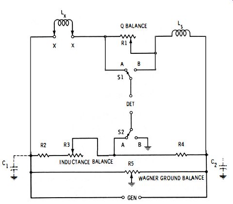
Fig. 4-8. Inductance bridge with Wagner ground.
Fig. 4-9 shows the basic circuit of the Hay bridge. Here, unknown inductance Lx is compared with standard capacitance Cs. The bridge is balanced in the conventional manner by adjusting inductance
balance rheostat R2 and Q-balance rheostat R3 for null . At null : where,
Cs is in farads, L is in henrys, R is in ohms, CsR1R2 Lx = 1 + (R32w2Cs2) w equals 27Tf (f is in Hz)
4-7
Since R3 appears in the denominator of the fraction, the inductance balance of this bridge is not independent of the Q balance.
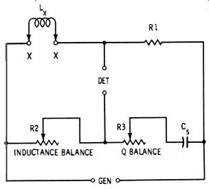
Fig. 4-9. Hay bridge.
Also, since w also appears in the equation, the balance is frequency dependent. However, if the Q of the test inductor, Lx, is higher than 10, the frequency may be ignored, and equation 4-7 may be simplified, with an error of less than 1 percent : Lx = Cs (R1R2) 4-8 At null, the equivalent resistance of the unknown inductor also may be determined:
W2Cb 2R 1 R2R3 Rx = 1 + (W2Cb2R32

Fig. 4-10. Maxwell bridge.
From this, the Q of the unknown inductor may be determined : Qx = (wLx) /Rx 4-9 4- 10
Again, note that the settings of both the inductance-balance and Q-balance rheostat enter into the calculation, and that the Rx determination, like that of Lx, is frequently dependent. However, if the Q of inductor Lx is higher than 10, equation 4-9 may be simplified:
4- 11
4.9 MAXWELL BRIDGE
The basic circuit of the Maxwell bridge is shown in Fig. 4-10. This circuit compares unknown inductance Lx with standard capacitance Cs. It differs from the Hay bridge, just described, in the parallel connection of the Q-balance rheostat (R3 ) and standard capacitor (CR) . In this circuit, the inductance balance and Q balance are independent of each other and each is independent of the frequency. At null : where, Cs is in farads, Lx is in henrys.
R is in ohms.
Lx = Cs ( R1R2)
4- 12
The equivalent resistance (Rx) of the unknown inductor is calculated : Rx = R1 (R2/R3 )
4- 13
4.10 ANDERSON BRIDGE
Fig. 4- 11 shows the basic circuit of the Anderson bridge. This is a six-impedance network (Lx, Cs, R1, R2, R3, R4 ) in which unknown inductance Lx is compared with standard capacitance Cs. This circuit is somewhat harder to adjust than is the usual four-impedance bridge, but it offers a wider range.
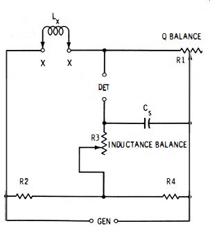
Fig. 4-11. Anderson bridge.
In the Anderson bridge, the inductance balance and Q balance are independent of each other and are independent of the frequency.
At null : Lx = Cs[R3 (1 + R2/R4 ) + R2] where, Cs is in farads, Lx is in henrys, R is in ohms.
4- 14
The equivalent resistance (Rx) of the unknown inductor is calculated:
Rx = (R1R2) /R4 4- 15
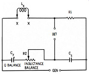
Fig. 4-12. Owen bridge.
4. 11 OWEN BRIDGE
Fig. 4- 12 shows the basic circuit of the Owen bridge. In this arrangement, a variable capacitor (Cr ) is employed for the Q balance .
(If a suitable variable capacitor is not available, a variable resistor may be connected in series with inductor Lx, and a fixed capacitance used at Cr. ) The inductance balance and Q balance are independent of each other and of the frequency.
The Owen bridge provides an extremely wide inductance range for a narrow range of Cs and R values. At null : where, Cs is In farads, Lx is in henrys, R is in ohms.
Lx = Cs ( R1R2)
4- 16
The equivalent resistance (Rx) of the unknown inductor may be calculated:
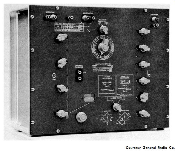
Fig. 4-13. Laboratory-type inductance bridge employing Owen circuit.
4-17
…where Cr and Cs are both in the same unit of capacitance.
Fig. 4-13 shows a laboratory-type inductance bridge (General Radio Type 1632-A) employing the Owen circuit. This instrument covers the range from 0.000 1 p,h to 1111 hy and provides for either series or parallel connection of the Q-balance capacitor to the inductance-balance rheostat. An external generator and detector are required.
4.12 INDUCTANCE BRIDGE WITH DC POLARIZATION
The inductance of an iron-core inductor (and of some inductors having cores of magnetic material other than iron ) has a different value when the coil is carrying direct current simultaneously with the a-c signal than when no direct current is present. Moreover, the inductance varies with the amount of direct current. This situation necessitates that the inductance of such coils be measured while they are conducting rated d-c operating current.
Fig. 4-14 shows two bridge circuits for measuring inductance under conditions of d-c polarization. In Fig. 4- 1 4A, the conventional inductance comparison bridge has been equipped for this application by applying direct current to inductor Lx through filter choke Lr, d-c ammeter or milliammeter M, current-adjusting rheostat R2, and extension-arm resistor R3. In all other respects, the circuit is identical to the inductance comparison bridge shown earlier in Fig. 4-6. The direct current is set to the required operating level by adjustment of rheostat R2, and is indicated by current meter M. Filter choke Lt, whose inductance must be many times that of unknown inductor Lx and which must be able to carry the maximum direct current safely and without saturating, prevents short circuit of the a-c bridge signal by the d-c supply. Similarly, blocking capacitor C1 prevents short circuit of the d-c supply by the bridge circuit. In this arrangement, the direct current passes through the inductance-balance rheostat (R4) and extension-arm resistor (R3). In Fig. 4- 14B, the Hay bridge has been adapted by applying the d-c voltage in parallel with the a-c signal voltage. The direct current is set to the required operating level by means of rheostat R4 and direct-current meter M. Filter choke Lt, whose inductance must be much higher than that of unknown inductor Lx and which must be able to carry the maximum direct current without saturating, prevents short circuit of the a-c signal by the d-c supply. Similarly, capacitor Ch prevents short circuit of the d-c supply by the a-c generator. The direct current passes through bridge resistor R1, so this resistor must be rated to carry this current safely.
4. 13 MUTUAL-INDUCTANCE MEASUREMENT
Mutual inductance, as well as self-inductance, may be measured by the bridge method. Fig. 4- 15 shows two bridge circuits used for this purpose .
(A) Inductance comparison bridge. (B) Hay bridge.
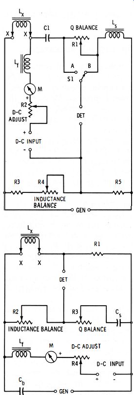
Fig. 4-14. Inductance bridges with dc polarization
In the comparison bridge shown in Fig. 4- 15A, unknown mutual inductance Mx is compared with standard self-inductance LB. Here, coil Lm of the mutual inductor constitutes the lower right arm of the bridge. (Inductance L must be known.) The bridge is balanced by adjustment of rheostat R2. At null :
(A) Lx-Mx comparison bridge.
(b) Carey-Foster mutual-inductance bridge.
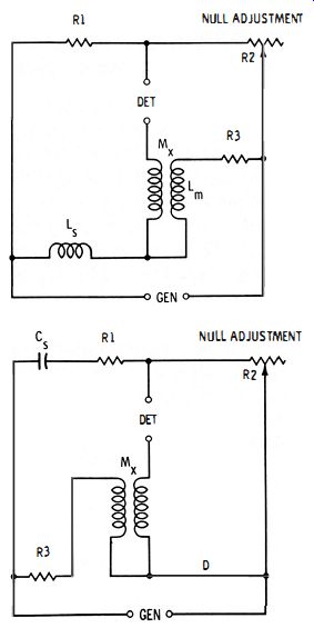
Fig. 4-15. Mutual-inductance bridges.
M = (Lm R1 /R2) - Ls x 1 + (R1/R2 )
where,
L_m, L_s, and Mx are in henrys,
R1 and R2 are in ohms.
4- 18
In the Carey-Foster mutual-inductance bridge in Fig. 4- 15B, unknown mutual inductance Mx is compared with standard capacitor Cs.
In this circuit, the lower right arm (D) of the bridge has zero resistance, which frees the null from frequency dependence. The bridge is balanced by adjustment of rheostat R2. At null : where, Cs is in farads Mx is in henrys, Mx = Cs (R2R3 ) R2 and R3 are in ohms.
4-19
4.14 SUBSTITUTION METHOD OF INDUCTANCE MEASUREMENT
The same kind of trouble experienced in measuring small capacitances is encountered in measuring small inductances. That is, residual inductances in the bridge wiring and components, being of approximately the same magnitude as the small unknown inductance, restrict the smallest value which can be measured. They also make erroneous those values which can be measured. This difficulty is overcome by the substitution method, which resembles the similar method of capacitance measurement.
Fig. 4-16 shows a bridge employing the substitution method. This circuit employs a calibrated variable inductor (L_), which may be several series-connected inductance decades or a continuously variable laboratory inductor (either one will be direct reading in henrys, milli-henrys, or microhenrys ). Unknown inductor Lx is connected to terminals X-X by the shortest possible leads. The bridge is operated as follows :
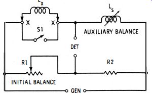
Fig. 4-16. Substitution inductance bridge.
1. Switch S1 first is closed to short-circuit unknown inductor Lx· The standard inductor, Ls, is set to its lowest value (recorded here as L1 ), and the bridge is balanced by adjustment of rheostat R1. This rheostat then need not be disturbed.
2. Next, switch S1 is opened. This inserts Lx into the circuit and unbalances the bridge.
3. Variable inductor La then is adjusted to restore the bridge balance, and its new inductance setting recorded as L2.
4. Finally, the unknown inductance is calculated from the two settings of the variable inductor: 4-20 where the L's are in the same units : henrys, millihenrys, or microhenrys.
Inductance values of 0.1 uH or lower may be accurately measured by means of the substitution method. This method automatically takes into account the residual inductances of the circuit.